EP0831440A1 - Drahtloser Selektivrufempfänger und Verfahren zur Anzeige von empfangenen Nachrichten - Google Patents
Drahtloser Selektivrufempfänger und Verfahren zur Anzeige von empfangenen Nachrichten Download PDFInfo
- Publication number
- EP0831440A1 EP0831440A1 EP97115939A EP97115939A EP0831440A1 EP 0831440 A1 EP0831440 A1 EP 0831440A1 EP 97115939 A EP97115939 A EP 97115939A EP 97115939 A EP97115939 A EP 97115939A EP 0831440 A1 EP0831440 A1 EP 0831440A1
- Authority
- EP
- European Patent Office
- Prior art keywords
- registration
- group
- message
- groups
- received messages
- Prior art date
- Legal status (The legal status is an assumption and is not a legal conclusion. Google has not performed a legal analysis and makes no representation as to the accuracy of the status listed.)
- Withdrawn
Links
Images





Classifications
-
- G—PHYSICS
- G08—SIGNALLING
- G08B—SIGNALLING SYSTEMS, e.g. PERSONAL CALLING SYSTEMS; ORDER TELEGRAPHS; ALARM SYSTEMS
- G08B5/00—Visible signalling systems, e.g. visible personal calling systems or remote indication of seats occupied
- G08B5/22—Visible signalling systems, e.g. visible personal calling systems or remote indication of seats occupied using electric transmission; using electromagnetic transmission
- G08B5/222—Personal calling arrangements or devices, i.e. paging systems
- G08B5/223—Personal calling arrangements or devices, i.e. paging systems using wireless transmission
- G08B5/224—Paging receivers with visible signalling details
- G08B5/227—Paging receivers with visible signalling details with call or message storage means
Definitions
- the present invention is generally related to a selectively called wireless receiver having a message display function and a method for displaying received messages. More specifically, the present invention is directed to such a selectively called wireless receiver and a method for displaying received messages, capable of quickly finding out a desirable message from a plurality of received messages.
- wireless receivers having a message display function are provided widely.
- the selectively called wireless receiver of this type accumulates received messages in a message memory. Then, the received messages, which have been accumulated in the message memory, are displayed on a display unit according to the operation performed by the user.
- the selectively called wireless receiver of this type is required to have high functionality.
- the function is required that one desirable message can be quickly chosen from among a plurality of received messages and then displayed.
- a selectively called wireless receiver is proposed to classify received messages into a plurality of groups.
- the received messages are read from the message memory every group and then the read messages are displayed on a display unit.
- a selectively called wireless receiver which is disclosed in Japanese Laid Open Patent Disclosure (JP-A-Heisei 3-23727) has a plurality of call numbers and stores a received message into a message memory based on a corresponding one of these call numbers. Then, when a switch for the corresponding call number is operated, the received message corresponding to the call number is read and then the read message is displayed on a display unit.
- this conventional technique is called the first conventional example.
- JP-A-Heisei 7-264644 classifies received messages into groups according to message distinguishing codes and stores the classified received messages into a message memory. Thereafter, the stored messages are read every group and then are displayed on the display unit.
- this conventional technique is called the second conventional example.
- the switch to read messages must be provided every call number. For instance, considering a case to receive information service, because the number of call numbers increases with increase of kinds of information service to be provided, the number of switches also increases. As a result, there is a problem that the design of an apparatus becomes difficult.
- a selectively called wireless receiver displays messages in order one by one from the group which contains a lot of received messages. As a result, the message having high urgency can be first displayed.
- the present invention is accomplished to solve the above-mentioned problems and has an object to provide a selectively called wireless receiver capable of quickly providing a message desired by the user without causing increase of the apparatus scale.
- Another object of the present invention is to provide a method for displaying received messages capable of quickly providing a message desired by the user.
- a selectively called wireless receiver includes:
- the selectively called wireless receiver may be arranged by further comprising: a group name storing section for storing a plurality of pairs, wherein each of the pairs corresponds to one of the groups, and is composed of a group name and a registration flag; and a registration control section for registering each of the groups by setting the registration flag and canceling the registration of each of the groups by clearing the registration flag, wherein the group name control section selectively displays the group names based on the registration flag on the display unit.
- the selectively called wireless receiver may be arranged by further comprising: a switch section, and wherein the group selecting section chooses the group name from among the group names displayed on the display unit based on an operation of the switch section.
- the above-described message classifying section may be arranged to classify the received messages into the plurality of groups based on a kind of each of the received messages, wherein the kind is defined by a call ID included in each of the received messages.
- the call ID may be allocated to one of service of selective call services and information services.
- the kind may be defined by a part of message data included in each of the received messages.
- the above-described group name control section may be arranged to display the group names on the display unit in a list form.
- the above-described message storing section may be arranged to store entire of received messages regardless of the registration flag.
- the selectively called wireless receiver may be arranged by further comprising: a registration candidate group name control section for displaying unregistered group names as registration candidate group names when each of the groups is registered by the registration control section.
- the selectively called wireless receiver may be arranged further comprising: a registration cancellation candidate group name control section for displaying registered group names as registration cancellation candidate group names when the registration of each of the groups is cancelled by the registration control section.
- the selectively called wireless receiver may be arranged further comprising: a confirmation message control section for displaying a confirmation message when entire of the registration of the groups is cancelled by the registration control section.
- a method for displaying received messages comprising the steps of:
- the method for displaying received messages according to the another aspect of the present invention may be arranged further comprising the steps of: displaying unregistered group names as registration candidate group names when each of the groups is registered.
- the method for displaying received messages according to the another aspect of the present invention may be arranged further comprising the steps of: displaying registered group names as registration cancellation candidate group names when the registration of each of the groups is cancelled.
- the method for displaying received messages according to the another aspect of the present invention may be arranged further comprising the steps of: displaying a confirmation message when entire of the registration of the groups is cancelled.
- Fig. 1 is a schematic block diagram showing the structure of the selectively called wireless receiver.
- an antenna 1 efficiently converts electromagnetic wave energy into an electric received signal in which a sync (synchronization) signal, a call signal and a message signal are contained.
- the electric signal is supplied to a receiving section 2.
- the receiving section 2 demodulates this electric signal to a base band signal.
- the demodulated base band signal is supplied to a decoding section 3.
- the decoding section 3 detects a sync signal in the base band signal and then reads the received signal based on this detected sync signal. Also, the decoding section 3 checks whether or not a call number contained in the received signal is same as a call ID allocated to the present selectively called wireless receiver (hereinafter called "a self-call ID"). In this embodiment, the self-call ID has been stored in an ID storing section 5. When, it is determined that the same call number as the self-call ID is contained in the received signal, the decoding section 3 decodes the message signal following the self-call ID.
- Fig. 2 shows a signal format of the POCSAG (Post Office Code Standardization Advisory Group) system employed in this embodiment. Because a reception operation of the selectively called wireless receiver of this type is generally known, a detailed explanation will be omitted. However, referring to Fig. 2, an operation of the above-mentioned decoding section 3 will be simply described.
- POCSAG Post Office Code Standardization Advisory Group
- the decoding section 3 establishes the bit synchronization of the received signal in accordance with a preamble signal 21 and detects a frame sync signal 22. Thereby, a reading timing of each word is recognized.
- Fig. 2 shows such an example that a self-call ID signal 23 is located in the third field from the frame sync signal.
- the decoding section 3 detects this self-call ID signal 23
- the decoding section 3 receives message words M1 (24), M2 (25) and M3 (26) (3 words, i.e. alphabet 8 characters in this example) which follows this self-call ID signal 23.
- the decoding section 3 detects another ID signal or an IDLE signal 27, the decoding section 3 recognizes that transmission of the message signal is complete. It should be noted that a transmission device sends out the IDLE signal when there are not a call signal and a message signal to be sent out.
- the decoding section 3 converts the received message signals M1 (24) to M3 (26) into ASCII codes and stores the converted ASCII codes in a message storing section 6 through a message processing section 4.
- the ID storing section 5 stores equal to or more than one IDs (ID1, ID2, ID3, ⁇ , IDn). Each ID can be allocated to one of selective call services and information services such as a weather forecast, news. Also, if well known technique is used, the message word M1 can be allocated to an information service distinguishing code and the message words M2, M3, ⁇ can be allocated to message data. In this case, only one ID is used for the information service.
- the message storing section 6 stores the received messages which are classified into a plurality of groups such as the selective call, the information service and so on.
- a group name storing section 7 stores a plurality of pairs each of which is composed of a group name and a registration flag. Each of the pairs corresponds to one group of received messages.
- Fig. 3 shows an example of contents in the group name storing section 7.
- the registration flag is used for the control of whether or not the group name corresponding to the registration flag is displayed in a group name list (to be mentioned in detail later).
- the registration flag is used for the control of whether or not a request to read the message that belongs to each group is received. A method of setting the registration flag will be mentioned later.
- Fig. 4 shows an example of contents in the message storing section 6 in which the received messages are stored every group name.
- one or more kinds of memories can be used for the ID storing section 5, the message storing section 6 and the group name storing section 7.
- an EEPROM may be used for the ID storing section 5 and the group name storing section 7, and a RAM may be used for the message storing section 6.
- a RAM may be used for all of these.
- the decoding section 3 drives an informing section 8 when the self-call ID signal is detected and the message signal is received. As a result, a sound is generated from a speaker 9 to thereby inform the reception of the message signal.
- various types of informing devices such as a vibrator which informs by vibration, a light-emitting diode which informs by light may be used for the informing section 8.
- the decoding section 3 or the informing section 8 may be equipped with a auto-reset function. In this case, the sound generation is stopped when the predetermined time is elapsed after the sound generation is started.
- the decoding section 3 may be equipped with a manual reset function to stop the sound generation from the speaker 9.
- the decoding section 3 is driven through the message processing section 4 according to an operation of a menu switch 10, selector switch 11, background word switch 12 or forward switch 13.
- the display driving section 14 is driven through the message processing section 4 to display the received messages on a display unit 15.
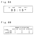
- Step S60 When a power supply (not shown) of this selectively called wireless receiver is turned ON or a reset operation is performed, an initializing process is first executed (Step S60). In this process, hardware in the selectively called wireless receiver is initialized, and initial values are set to the message storing section 6 and the group name storing section 7. When this initializing process is completed, the selectively called wireless receiver enters a wait state (Step S61). In this wait state, a message shown in Fig. 6A is displayed on the display unit 15. When either on of switches 10-13 is operated in this wait state, the selectively called wireless receiver operates as follows.
- Step S62 it is checked whether or not the menu switch 10 is operated.
- the sequence operation advances to a menu selection mode processing (Steps S79 to S120) which will be described later.
- Step S63 it is checked whether or not the selection switch 11 is operated. In this step, even if it is determined that the selection switch 11 is operated, the sequence operation advances to a next Step S64. That is, the operation of the selection switch 11 is ignored in this condition.
- Step S64 it is checked whether or not the backward switch 12 is operated.
- Step S65 it is checked whether or not the forward switch 13 is operated.
- the sequence operation returns to the Step S61. In short, when neither of the backward switch 12 and the forward switch 13 is operated, the selectively called wireless receiver enters the wait state again.
- Step S66 When it is determined that the backward switch 12 is operated in the above Step S64, or the forward switch 13 is operated in the above Step S65, the group name list is displayed on the display unit 15 (Step S66). In short, when the backward switch 12 or the forward switch 13 is operated in the wait state, the group name list is displayed on the display unit 15. In this case, only group names corresponding to the registration flag which has been set in "1" are included in the group name list.
- Fig. 7A shows an example of the group name list. First, a screen 100 shown in Fig. 7 is displayed as a initial group name list in which a cursor is located in front of a group name at a headline.
- Step S67 a check is done to see whether or not the forward switch 12 is operated.
- Step S69 the sequence operation advances to Step S69.
- the cursor is carried forward for 1 line (Step S68) as shown in Fig. 7B. Thereafter, the sequence operation advances to Step S69.
- step 69 it is checked whether or not the backward switch 12 is operated. Then, when it is determined that the backward switch 12 is not operated, the sequence operation advances to Step S71. On the other hand, when it is determined that the backward switch 12 is operated, the cursor is carried backward for 1 line (Step S70). Thereafter, the sequence operation advances to Step S71.
- Step S71 it is checked whether or not selection switch 11 is operated.
- the sequence operation advances to a message display processing (Steps S73 to S78) which will be mentioned later.
- Step S72 it is checked whether or not the menu switch 10 is operated.
- the sequence operation returns to the Step S67. Thereafter, the above-described sequence operations of Steps S67 to S72 are repeatedly carried out.
- the sequence operation branches to the Step S61. As a consequence, the selectively called wireless receiver enters the wait state again.
- Steps S67 to S72 when the forward switch 13 is operated, the cursor is carried forward for 1 line. As a result, the display content on the display unit 15 is changed like screen 100 ⁇ screen 101 ⁇ screen 102 ⁇ screen 103 ⁇ . It should be noted that when the forward switch 13 is operated in the state that the screen 102 has been displayed, the screen is scrolled up as shown as the screen 103 in Fig. 7D. Thereby, a new group name and a cursor are displayed on the bottom line on the display unit 15.
- one message is first displayed (Step S73). More specifically, first, one group corresponding to the group name indicated by the cursor is selected. Then, a head message, which belongs to the selected group, is read from the message storing section 6 and is displayed on the display unit 15. Consequently, the user can see a desired message by adjusting the cursor to the desired group name by operating the forward switch 13, the backward switch 12 and the selection switch 11.
- Fig. 6B shows a display example of the received message displayed when a group name of "weather forecast (local)" is selected.
- Step S74 a check is done of whether or not the forward switch 13 is operated.
- Step S76 a following message is displayed (Step S75). That is, a message immediately after the currently displayed message is read from the message storing section 6 and is displayed on the display unit 15. Thereafter, the sequence operation advances to Step S76.
- Step S76 it is checked whether or not the backward switch 12 is operated.
- the sequence operation advances to Step S78.
- a previous message is displayed (Step S77). That is, a message immediately previous to the currently displayed message is read from the message storing section 6 and is displayed on the display unit 15. Thereafter, the sequence operation advances to Step S78.
- Step S78 it is checked whether or not the menu switch 10 is operated.
- the sequence operation returns to the Step S74. Thereafter, the above-described sequence operations of Steps S74 to S78 are repeatedly carried out.
- the sequence operation branches to the Step S61.
- Steps S74 to S78 the next message is displayed according to the operation of the forward switch 13 and the previous message is displayed according to the operation of the backward switch 12. Consequently, the user can find a desired message by operating the forward switch 13 and the backward switch 12.
- a menu is first displayed (Step S79).
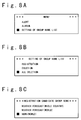
- the menu shown in Fig. 8A is displayed on the display unit 15.
- the selectively called wireless receiver enters a menu selection mode.
- the menu contains items such as "ALERT”, “ALARM”, "SETTING OF GROUP NAME LIST”.
- Step S80 to S83 a processing for moving the cursor according to the operation of the forward switch 13 and the backward switch 12 (hereinafter, called “a cursor processing") is performed (Steps S80 to S83).
- This cursor processing is the same as the processing performed in above-mentioned Steps S67 to S70.
- Step S84 it is checked whether or not the selection switch 11 is operated.
- Step S86 it is checked whether or not the menu switch 10 is operated.
- Step S85 the sequence operation returns to the Step S80.
- the above-described sequence operations of Steps S80 to S85 are repeatedly carried out.
- the sequence operation branches to the Step S61.
- Steps S80 to S85 when the forward switch 13 is operated, the cursor is carried forward for 1 line. Similarly, when the backward switch 12 is operated, the cursor is carried backward for 1 line. Consequently, the user can select a desired item from a plurality of the items in the menu.
- Step S86 it is checked whether or not the selected item is "ALERT" (Step S86).
- the sequence operation advances to Step S88.
- alert processing is performed (Step S87). In this alert processing, a method of informing a warning can be set. After that, the sequence operation branches to Step S61.
- Step S88 a check is done of whether or not the selected item is "ALARM".
- the sequence operation advances to Step S90.
- an alarm processing is performed (Step S89). In this alarm processing, a setting of the time of morning call, an informing method of the morning call and so on can be set. After that, the sequence operation branches to Step S61.
- Step S90 it is checked whether or not the selected item is "SETTING OF GROUP NAME LIST".
- the sequence operation returns to the Step S61.
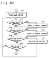
- display processing to set the group name list shown in Fig. 5D is firstly performed (Step S91). In this step, a screen shown in Fig. 8B is displayed.
- Step S92 the cursor processing is performed (Steps S92 to S95). Subsequently, it is checked whether or not the selection switch 11 is operated (Step S96). When it is determined that the selection switch 11 is operated, the sequence operation branches to Step S98. On the other hand, when it is determined that the selection switch 11 is not operated, it is checked whether or not the menu switch 10 is operated (Step S97). In this step, when it is determined that the menu switch 10 is not operated, the sequence operation returns to the Step S92. Thereafter, the above-described sequence operations of Steps S92 to S97 are repeatedly carried out. On the other hand, when it is determined that the menu switch 10 is operated, the sequence operation branches to the Step S61.
- Steps S92 to S97 when the forward switch 13 is operated, the cursor is carried forward for 1 line. Similarly, when the backward switch 12 is operated, the cursor is carried backward for 1 line. Consequently, the user can select a desired item from the plurality of the items displayed in the menu (registration, deletion and all deletion).
- Step S98 it is checked whether or not the selected item is "REGISTRATION".
- the sequence operation advances to Step S101 to thereby execute registration processing (Steps S101 to S108) which will be mentioned later.
- Step S99 it is checked whether or not the selected item is "DELETION” (Step S99).
- Step S109 it is checked whether or not the selected item is "ALL DELETION” (Step S100).
- Step S117 When it is determined that "ALL DELETION" is selected, the sequence operation advances to Step S117 to thereby execute all deletion processing (Steps S117 to S120) which will be mentioned later. On the other hand, when it is determined that "ALL DELETION" is not selected, the sequence operation branches to the Step S61.
- registration candidate group name display processing is firstly performed (Step S101).
- this step as shown in Fig. 8C, non-registered group names are displayed as registration candidate group names in a list form.
- the cursor processing is performed (Steps S102 to S105).
- it is checked whether or not the selection switch 11 is operated (Step S106).
- a registration flag is set (Step S107). That is, the registration flag corresponding to the group name indicated by the cursor is set to "1". Thereafter, the sequence operation returns to the Step S102.
- Step S108 it is checked whether or not the menu switch 10 is operated.
- the sequence operation returns to the Step S102. Thereafter, the above-described sequence operations of Steps S102 to S108 are repeatedly carried out.
- the sequence operation branches to the Step S61.
- Steps S102 to S108 the user can set a registration flag corresponding to the desired group name to "1" by operating the forward switch 13, the backward switch 12 and the operating selection switch 11. Consequently, the newly selected group name is added to the group name list.
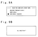
- deletion candidate group name display processing is firstly performed (Step S109). In this step, as shown in Fig. 9A, already registered group names are displayed as deletion candidate group names in a list form. Next, the cursor processing is performed (Steps S110 to S113). Subsequently, it is checked whether or not the selection switch 11 is operated (Step S114). When it is determined that the selection switch 11 is operated, the registration flag which has been set is cleared (Step S115). That is, the registration flag corresponding to the group name indicated by the cursor is reset to "0". Thereafter, the sequence operation returns to the Step S110.
- Step S116 it is checked whether or not the menu switch 10 is operated.
- the sequence operation returns to the Step S110. Thereafter, the above-described sequence operations of Steps S110 to S116 are repeatedly carried out.
- the sequence operation branches to the Step S61.
- Steps S110 to S116 the user can reset the registration flag corresponding to the desired group name to "0" by operating the forward switch 13, the backward switch 12 and the operating selection switch 11. Consequently, the selected group name is deleted from the group name list.
- Step S117 a confirmation message display processing is firstly performed (Step S117).
- a message for confirmation as shown in Fig. 9B, is displayed on the display unit 15.
- Step S118 it is checked whether or not the selection switch 11 is operated (Step S118). When it is determined that the selection switch 11 is operated, all registration flags are cleared (Step S119). Thereafter, the sequence operation branches to the Step S61.
- Step S120 it is checked whether or not the menu switch 10 is operated.
- the sequence operation returns to the Step S118. Thereafter, the above-described sequence operations of Steps S118 to S120 are repeatedly carried out.
- the sequence operation branches to the Step S61.
- Steps S118 to S120 the user can clear the all registration flags in "0" by the operating selection switch 11. Consequently, the group name list is initialized.
- received messages often include important information to the user and the information often has the nature that it should be confirmed at once when the message is received.
- the message of this type includes information such as a stock price and an exchange rate. These information changes every moment and also information value is very high.
- the control of whether or not a message is displayed is performed every message group.
- the selectively called wireless receiver according to this embodiment can quickly cope with the situation as described above.
- received messages are all stored in the message storing section 6 regardless of the registration flags.
- the user can confirm the contents of those messages by controlling the registration flags.
- the decoding section 3 checks whether or not the group name corresponding to the received message is included in the group name list by referring the registration flag through the message processing unit 4.
- the informing section 8 is started to inform a terminating call.
- the terminating call is not informed.
Landscapes
- Physics & Mathematics (AREA)
- Engineering & Computer Science (AREA)
- Computer Networks & Wireless Communication (AREA)
- Electromagnetism (AREA)
- General Physics & Mathematics (AREA)
- Mobile Radio Communication Systems (AREA)
Applications Claiming Priority (2)
| Application Number | Priority Date | Filing Date | Title |
|---|---|---|---|
| JP8246622A JP2908345B2 (ja) | 1996-09-18 | 1996-09-18 | 無線選択呼出受信機 |
| JP246622/96 | 1996-09-18 |
Publications (1)
| Publication Number | Publication Date |
|---|---|
| EP0831440A1 true EP0831440A1 (de) | 1998-03-25 |
Family
ID=17151150
Family Applications (1)
| Application Number | Title | Priority Date | Filing Date |
|---|---|---|---|
| EP97115939A Withdrawn EP0831440A1 (de) | 1996-09-18 | 1997-09-12 | Drahtloser Selektivrufempfänger und Verfahren zur Anzeige von empfangenen Nachrichten |
Country Status (3)
| Country | Link |
|---|---|
| EP (1) | EP0831440A1 (de) |
| JP (1) | JP2908345B2 (de) |
| CN (1) | CN1096199C (de) |
Citations (6)
| Publication number | Priority date | Publication date | Assignee | Title |
|---|---|---|---|---|
| JPH0323727A (ja) * | 1989-06-21 | 1991-01-31 | Matsushita Electric Ind Co Ltd | 選択呼出受信装置 |
| US5075684A (en) * | 1989-10-06 | 1991-12-24 | Motorola, Inc. | Selective call message management |
| EP0481814A2 (de) * | 1990-10-18 | 1992-04-22 | VENTANA SYSTEMS Inc. | Datenverarbeitungssystem |
| JPH04185055A (ja) * | 1990-11-20 | 1992-07-01 | Toshiba Corp | ファクシミリ装置 |
| JPH07131840A (ja) * | 1993-11-02 | 1995-05-19 | Casio Comput Co Ltd | 無線受信機 |
| EP0675467A1 (de) * | 1994-03-22 | 1995-10-04 | Nec Corporation | Selektiv-Rufempfänger mit Nachrichtenanzeigefunktion |
-
1996
- 1996-09-18 JP JP8246622A patent/JP2908345B2/ja not_active Expired - Lifetime
-
1997
- 1997-09-12 EP EP97115939A patent/EP0831440A1/de not_active Withdrawn
- 1997-09-18 CN CN97119547A patent/CN1096199C/zh not_active Expired - Lifetime
Patent Citations (6)
| Publication number | Priority date | Publication date | Assignee | Title |
|---|---|---|---|---|
| JPH0323727A (ja) * | 1989-06-21 | 1991-01-31 | Matsushita Electric Ind Co Ltd | 選択呼出受信装置 |
| US5075684A (en) * | 1989-10-06 | 1991-12-24 | Motorola, Inc. | Selective call message management |
| EP0481814A2 (de) * | 1990-10-18 | 1992-04-22 | VENTANA SYSTEMS Inc. | Datenverarbeitungssystem |
| JPH04185055A (ja) * | 1990-11-20 | 1992-07-01 | Toshiba Corp | ファクシミリ装置 |
| JPH07131840A (ja) * | 1993-11-02 | 1995-05-19 | Casio Comput Co Ltd | 無線受信機 |
| EP0675467A1 (de) * | 1994-03-22 | 1995-10-04 | Nec Corporation | Selektiv-Rufempfänger mit Nachrichtenanzeigefunktion |
Non-Patent Citations (3)
| Title |
|---|
| PATENT ABSTRACTS OF JAPAN vol. 015, no. 148 (E - 1056) 15 April 1991 (1991-04-15) * |
| PATENT ABSTRACTS OF JAPAN vol. 016, no. 499 (E - 1280) 15 October 1992 (1992-10-15) * |
| PATENT ABSTRACTS OF JAPAN vol. 095, no. 008 29 September 1995 (1995-09-29) * |
Also Published As
| Publication number | Publication date |
|---|---|
| JPH1094013A (ja) | 1998-04-10 |
| CN1096199C (zh) | 2002-12-11 |
| CN1179069A (zh) | 1998-04-15 |
| JP2908345B2 (ja) | 1999-06-21 |
Similar Documents
| Publication | Publication Date | Title |
|---|---|---|
| US5859594A (en) | Selective call receiver having selectable displays | |
| US6351656B1 (en) | Method and apparatus for displaying a message which has been received | |
| JP2990072B2 (ja) | 無線選択呼出受信機 | |
| EP0317230B1 (de) | Personenruffunkempfänger mit einer Nachrichtenauswahlschaltung | |
| JP3671468B2 (ja) | 受信装置及び表示制御方法 | |
| US5686900A (en) | Selective calling receiver with message display function | |
| JP3048946B2 (ja) | 無線選択呼出受信機 | |
| US6694136B2 (en) | Radio communication system, terminal equipment used therefor and service control station used therefor | |
| EP0831440A1 (de) | Drahtloser Selektivrufempfänger und Verfahren zur Anzeige von empfangenen Nachrichten | |
| JPH1094006A (ja) | 無線選択呼出受信機 | |
| KR19980024618A (ko) | 선택 호출 무선 수신기 및 수신 메시지를 디스플레이하는 방법 | |
| US5892456A (en) | Index managing method and apparatus of received messages for a radio paging receiver | |
| JP2990081B2 (ja) | 無線選択呼出受信システムおよび無線選択呼出受信方法 | |
| US5493602A (en) | Paging receiver capable of avoiding disturbance raised on reception of an unnecessary message | |
| US6621408B2 (en) | Pager capable of en bloc display of set of messages | |
| CA2109129C (en) | Radio selective call receiver with display | |
| US5864299A (en) | Method and apparatus for reducing overhead in a messaging system | |
| KR19980033376A (ko) | 선택 호출 수신기 및 선택 호출 수신기에서의 메시지 표시 방법 | |
| JP3797782B2 (ja) | メッセージ受信機 | |
| JP3611459B2 (ja) | 選択呼出受信機 | |
| JP2000059836A (ja) | 無線選択呼出受信機 | |
| WO1991009504A1 (en) | Multiple format signalling protocol for a selective call receiver | |
| JPH0779459A (ja) | 選択呼出受信機 | |
| JPH11168766A (ja) | メッセージ受信機 | |
| JPH10271546A (ja) | 無線選択呼出受信機 |
Legal Events
| Date | Code | Title | Description |
|---|---|---|---|
| PUAI | Public reference made under article 153(3) epc to a published international application that has entered the european phase |
Free format text: ORIGINAL CODE: 0009012 |
|
| AK | Designated contracting states |
Kind code of ref document: A1 Designated state(s): DE GB |
|
| AX | Request for extension of the european patent |
Free format text: AL;LT;LV;RO;SI |
|
| 17P | Request for examination filed |
Effective date: 19980706 |
|
| AKX | Designation fees paid |
Free format text: DE GB |
|
| RBV | Designated contracting states (corrected) |
Designated state(s): DE GB |
|
| 17Q | First examination report despatched |
Effective date: 20000620 |
|
| STAA | Information on the status of an ep patent application or granted ep patent |
Free format text: STATUS: THE APPLICATION HAS BEEN WITHDRAWN |
|
| 18W | Application withdrawn |
Withdrawal date: 20000822 |