EP0831673A2 - Implantierbares Mikrofon - Google Patents
Implantierbares Mikrofon Download PDFInfo
- Publication number
- EP0831673A2 EP0831673A2 EP97114603A EP97114603A EP0831673A2 EP 0831673 A2 EP0831673 A2 EP 0831673A2 EP 97114603 A EP97114603 A EP 97114603A EP 97114603 A EP97114603 A EP 97114603A EP 0831673 A2 EP0831673 A2 EP 0831673A2
- Authority
- EP
- European Patent Office
- Prior art keywords
- microphone
- housing
- electrical
- implantable
- membrane
- Prior art date
- Legal status (The legal status is an assumption and is not a legal conclusion. Google has not performed a legal analysis and makes no representation as to the accuracy of the status listed.)
- Granted
Links
Images


Classifications
-
- H—ELECTRICITY
- H04—ELECTRIC COMMUNICATION TECHNIQUE
- H04R—LOUDSPEAKERS, MICROPHONES, GRAMOPHONE PICK-UPS OR LIKE ACOUSTIC ELECTROMECHANICAL TRANSDUCERS; ELECTRIC HEARING AIDS; PUBLIC ADDRESS SYSTEMS
- H04R25/00—Electric hearing aids
- H04R25/60—Mounting or interconnection of hearing aid parts, e.g. inside tips, housings or to ossicles
- H04R25/604—Mounting or interconnection of hearing aid parts, e.g. inside tips, housings or to ossicles of acoustic or vibrational transducers
- H04R25/606—Mounting or interconnection of hearing aid parts, e.g. inside tips, housings or to ossicles of acoustic or vibrational transducers acting directly on the eardrum, the ossicles or the skull, e.g. mastoid, tooth, maxillary or mandibular bone, or mechanically stimulating the cochlea, e.g. at the oval window
-
- H—ELECTRICITY
- H04—ELECTRIC COMMUNICATION TECHNIQUE
- H04R—LOUDSPEAKERS, MICROPHONES, GRAMOPHONE PICK-UPS OR LIKE ACOUSTIC ELECTROMECHANICAL TRANSDUCERS; ELECTRIC HEARING AIDS; PUBLIC ADDRESS SYSTEMS
- H04R1/00—Details of transducers, loudspeakers or microphones
- H04R1/08—Mouthpieces; Microphones; Attachments therefor
-
- A—HUMAN NECESSITIES
- A61—MEDICAL OR VETERINARY SCIENCE; HYGIENE
- A61N—ELECTROTHERAPY; MAGNETOTHERAPY; RADIATION THERAPY; ULTRASOUND THERAPY
- A61N1/00—Electrotherapy; Circuits therefor
- A61N1/18—Applying electric currents by contact electrodes
- A61N1/32—Applying electric currents by contact electrodes alternating or intermittent currents
- A61N1/36—Applying electric currents by contact electrodes alternating or intermittent currents for stimulation
- A61N1/36036—Applying electric currents by contact electrodes alternating or intermittent currents for stimulation of the outer, middle or inner ear
- A61N1/36038—Cochlear stimulation
-
- H—ELECTRICITY
- H04—ELECTRIC COMMUNICATION TECHNIQUE
- H04R—LOUDSPEAKERS, MICROPHONES, GRAMOPHONE PICK-UPS OR LIKE ACOUSTIC ELECTROMECHANICAL TRANSDUCERS; ELECTRIC HEARING AIDS; PUBLIC ADDRESS SYSTEMS
- H04R2225/00—Details of deaf aids covered by H04R25/00, not provided for in any of its subgroups
- H04R2225/67—Implantable hearing aids or parts thereof not covered by H04R25/606
Definitions
- the system essentially only contains decoding and driver circuits for the Stimulation electrodes; the acoustic sound recording, the conversion of this sound signal into Electrical signals and their further processing are basically done externally in one so-called speech processor, which is worn on the outside of the body.
- the speech processor sets the preprocessed signals appropriately encoded to a high-frequency carrier signal um, which via an inductive coupling through the closed skin (transcutaneously) to the Implant is transferred.
- the sound-picking microphone is without exception outside the body and in most applications in one on the ear cup worn housing of a behind-the-ear hearing aid (BTE) and is connected to a cable connected to the speech processor.
- BTE behind-the-ear hearing aid
- Electromechanical systems are based on various physical transducer principles realized as e.g. through electromagnetic and piezoelectric systems.
- EP-A-0 499 940 (Leysieffer et al.), US-A-5 411 467 and EP-A-0 400 630 (Hortmann and Leysieffer), US-A-3 764 748 (Branch et al.), US-A-4 352 960 (Dormer et al.), US-A-5 015 225 (Hough et al.), US-A-5 015 224 (Maniglia), US-A-3 557 775 (Mahoney), US-A-3 712 962 (Eply), US-A-4 988 333 (Engebretson et al.), EP-A-0 263 254 (Schaefer), WO-A-92/09181 (Perkins) and WO-A-93/06666 (Buchele).
- Engebretson et al. (US-A-4 988 333) describe an implantable acoustic coupler system, one with a thin, circular example of silicone Membrane closed chamber is designed as a sound-absorbing element. Exemplary can this membrane over a thin coupling wire, which is the focus of the Membrane is attached, mechanically firmly connected to the hammer of the ossicular chain, which causes the eardrum vibrations as an acoustic signal within the chamber be mapped.
- the sound signal is sent to a microphone, which is off
- a microphone which is off
- This system was developed in one miniaturized embodiment (4.0 mm diameter of the dome chamber) in its principal function tested in a two-week animal model (Deddens et al .: "Totally implantable hearing aids: the effects of skin thickness on microphone function", At the. J. Otolaryngol. 1990, 11, pp. 1-4), the acoustic dome chamber with a 100 ⁇ m thick silicone disc as the sound entry membrane was completed.
- the basic principle of sound transmission via a hose element is from other authors (Mahoney, US-A-3 346 704 and US-A-3 557 775, Nunley et al., U.S.-A-3,882,285, Leysieffer et al., DE-A-39 40 632).
- the actual microphone element is placed in an encapsulated implant housing in all cases described.
- the sound is introduced to this microphone via a mechanically rigid or flexible Hose, the input end of which is closed, for example, with a thin membrane over which the incident sound signal is recorded.
- Mahoney the area of the mastoid behind the outer ear (hose end with Membrane under the closed skin over the mastoid), in Nunley et al.
- the area of the external auditory canal, the supply tube being removed from the thin skin of the auditory canal wall is covered, and Leysieffer et al. the tympanic cavity itself, into which the a thin membrane sealed end of the sound supply hose protrudes.
- a cylindrical stainless steel case is circular on one side thin stainless steel membrane hermetically sealed. Is inside this case a conventional miniature electret microphone housed, the sound inlet opening also protrudes into a tight space that extends from the housing membrane and an internal partition is formed.
- the three electrical microphone connections are via a three-pole hermetic signal feedthrough, which is next to the microphone capsule is placed out of the stainless steel housing and are connected with the subsequent implantable microphone connection line connected.
- the inside of the housing is off Filled with an inert gas (argon) for reasons of corrosion protection.
- the housing is in the mastoid cavity so implanted that the housing side with the circular membrane in a corresponding hole in the posterior wall of the auditory canal of the bony area of the ear canal is placed and the skin of the ear canal is completely covered in there is direct mechanical contact with the thin stainless steel membrane.
- the metal membrane with the overlying ear canal skin set in mechanical vibrations, which leads to a pressure fluctuation in the leads to small-volume space inside the housing.
- This pressure fluctuation is picked up by the internal microphone as a corresponding acoustic signal and converted into an electrical signal via the connecting line of the further processing Electronics can be supplied.
- the system is designed so that the first mechanical resonance of the vibratable metal membrane spectrally at the upper end of the audiological transmission range and the sound pressure transmission measure below this resonance is frequency independent and therefore no linear distortion occur.
- the ear canal skin essentially represents an additive dynamic mass coating for the vibratable membrane, so that the resonance frequency with coating with the skin compared to idling without skin covering only at lower frequencies shifts without the transmission dimension and thus the overall microphone sensitivity changed.
- the design is designed so that the resonant frequency in the implanted Condition, i.e. with covering with the ear canal skin, is at 3 to 5 kHz and thus at least basically the audiologically important frequency range can be transmitted.
- the sound pressure transmission factor is approx. 2 mV / Pa. This value is considered sufficient for electronic processing with an acceptable signal-to-noise ratio designated.
- the external dimensions of this cylindrical microphone module are 8.0 mm in diameter and 4.0 mm in height.
- this module has one major disadvantage: extensive clinical investigations have shown that it is impossible to place a cylindrical module with a total diameter of 8.0 mm in the bony area of the ear canal and thus in a hole in the ear canal wall to place that on the one hand there is a complete covering of the circular, flat surface with auditory canal skin and on the other hand it can be ensured that this module can be biostably implanted under long-term aspects.
- the outer auditory canal has a diameter of less than 10 mm and so a circular membrane with an 8.0 mm diameter cannot be called a touching, tangential surface, but rather represents a sectional plane, and secondly the removal of one such a large bony area in the auditory canal wall makes the adequate supply of the auditory canal skin remaining over the metal membrane seem extremely questionable.
- the microphone systems described can even be implanted in the bony area of the auditory canal or whether placement is only possible in the cartilaginous or soft tissue area of the auditory canal.
- the present invention describes a new variant for a fully implantable microphone for use in implantable hearing aid systems, the one based on the principle of a hermetic described by Suzuki and Yanigahara tight membrane housing, but due to a fundamentally modified housing geometry a significant reduction in the external dimensions while maintaining or Improvement of the functional operating parameters enables, this geometry the given natural anatomical conditions of the implantation site in the area of the Mastoid cavity and the posterior wall of the auditory canal is adapted.
- the housing in the case of an implantable microphone, it is used to stimulate the hearing Serving implantable hearing aid with a microphone capsule, all-round in a housing is hermetically sealed, and with an electrical bushing arrangement for performing at least one electrical connection from the interior of the Housing to the outside, the housing according to the invention at least two legs whose axes are aligned at an angle with respect to each other, the one leg holds the microphone capsule and provides it with a sound entry membrane and with the other leg opposite the plane of the sound entry membrane is set back and accommodates the electrical bushing arrangement in one area, the outside of a projection of the microphone capsule perpendicular to the sound entry membrane lies.
- the microphone housing must after mastoidectomy from the mastoid into the back wall of the auditory canal guided and placed there so that a mechanically safe contact of the whole Membrane surface with the ear canal skin overlying the drilled hole is achieved.
- the area of the microphone housing therefore advantageously has at least one length corresponds to the statistical maximum of the thickness of the posterior auditory canal wall.
- the microphone housing As for the microphone housing to be redesigned essentially determines the geometry and volume has the distance of the sigmoid sinus, whose outer contours are surgically derived from clinical For reasons that cannot be changed, exposed to the rear auditory canal wall. This very small distance in some individual anatomical relationships can constructively an entire axial arrangement of internal microphone capsule, electronic Components and the necessary hermetic signal implementation for the electrical Do not connect the microphone.
- the basic geometry of the microphone housing is selected that this housing basically consists of two legs that are at an angle to each other are arranged, the one leg, which is preferably cylindrical is, the microphone capsule and the sound-absorbing, preferably circular membrane contains and the other leg of the electrical bushing arrangement and preferably records electronic components, as will be explained in more detail below.
- the geometry of the microphone housing preferably chosen so that when the microphone is implanted in the mastoid cavity Leg that contains the sound entry membrane from the mastoid into an artificial hole protrudes into the back, bony ear canal wall and the sound entry membrane touches the skin of the ear canal wall and that the leg of the microphone housing, which contains the electrical bushing arrangement, placed in the area of the mastoid tip is. An enlargement of the mastoid cavity beyond a complete mastoidectomy is not necessary for this.
- the electrical bushing arrangement can be designed with multiple poles. With bipolar Execution, the arrangement is preferably made so that it using the electrical principle of phantom power works, i.e. that a pole together the useful signal potential and the energy supply DC potential for energy supply of the microphone. If the electrical bushing arrangement is single-pole, So this one pole can together the useful signal potential and the energy supply Direct voltage potential while a second pole of a supply line is connected to the microphone housing, which is electrically conductive for this purpose is carried out and the internal connection with the microphone cartridge circuit Leads to ground potential.
- the microphone housing in particular in the housing leg, which the electrical Implementation arrangement records, housed.
- electronic components that house an electrical impedance conversion and / or an electrical signal amplification and / or protective measures against electrical, magnetic and / or electromagnetic environmental influences.
- These latter measures usually include high-frequency capacitors and varistors in order to prevent the microphone module itself from being destroyed to protect high-energy electromagnetic interference, and on the other hand to minimize or suppress capacitive and inductive interference in the signal path, to disturbances in the further audio signal processing of the to the microphone module connected implant system.
- the microphone housing including the sound-absorbing membrane and the electrical Feedthrough device is preferably exemplary with biocompatible metals Made of pure titanium or biocompatible titanium alloys, made and hermetic on all sides sealed gastight.
- the microphone capsule housed in the microphone housing is particularly suitable for working after the electrodynamic, electromagnetic, dielectric and preferably designed according to the electret principle.
- it can be an electret miniature version with integrated field effect transistor for electrical impedance conversion act.
- the microphone can also be used in accordance with the condenser microphone principle LF or HF circuit can be executed.
- the microphone function can a semiconductor microphone can be realized in silicon technology, which with methodologies of Microsystem technology is built.
- connection line is preferably as a twisted pair or Coaxial line executed.
- the implantable microphone described here can be part of partially or fully implantable Hearing aids such as Cochlear implants with electrical stimulation of the auditory canal, Hearing aids with mechanical stimulation of the middle ear or inner ear as well be active masking systems for tinnitus treatment, which with adequate electronic Signal processing and energy supply systems and stimulation means Rehabilitation of a partial or complete failure or treatment by equipment allow impairment of one or both hearing organs.
- Hearing aids such as Cochlear implants with electrical stimulation of the auditory canal, Hearing aids with mechanical stimulation of the middle ear or inner ear as well be active masking systems for tinnitus treatment, which with adequate electronic Signal processing and energy supply systems and stimulation means Rehabilitation of a partial or complete failure or treatment by equipment allow impairment of one or both hearing organs.
- hearing aids are generally partially or fully implantable systems understand that with the help of the described microphone module, adequate electronic Signal processing and energy supply systems and stimulation means rehabilitation a partial or complete failure or the treatment of the equipment Allow impairment of one or both hearing organs.
- These include in particular Cochlear implants with electrical stimulation of the auditory pathway, implantable hearing aids with mechanical stimulation of the middle ear or inner ear as well as active, implantable Understanding masking systems for tinnitus treatment.
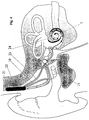
- Fig. 1 shows a cross section through the human ear with the outer ear 1 , the ear canal 2 , the bony ear canal wall 3 , the skin of the ear canal 4 , the eardrum 6 , the ossicular chain consisting of hammer 12 , anvil 13 and stirrup 14 , the inner ear ( Cochlea) 7 and the auditory nerve 8 .
- a microphone module which has a microphone housing 11 and is introduced in the area of the bony posterior auditory canal wall from the mastoid 9 , is drawn approximately to scale in the implanted state, the auditory canal wall skin 4 touching a membrane 5 which forms part of the microphone housing 11 .
- a first leg 31 of the microphone housing 11 which has an electrical lead-through arrangement 17 with a connected line 10 , the axis of which is schematically indicated at 35 in FIG. 2 , points approximately in the direction of the mastoid tip in the implanted state.
- the electrical bushing arrangement 17 is located in a region of the leg 31 which lies outside a projection of the microphone capsule 15 perpendicular to the sound entry membrane 5 .
- Fig. 2 the microphone housing 11 is shown schematically in the implanted state in cross section as a view of the opened mastoid cavity 18 after mastoidectomy.
- the microphone housing 11 is inserted with a microphone capsule 15 receiving the second housing leg 32 into a corresponding artificial bore 33 in the bony auditory canal wall 3 in such a way that the skin 4 of the auditory canal mechanically touches the circular membrane 5 and on the entire circular surface of the membrane.
- the housing leg 32 has an axis 36 ( FIG. 2 ) which, in the illustrated embodiment, is substantially at right angles to the axis 35 of the housing leg 31 .
- the area of the wall of the auditory canal that touches the membrane, together with the membrane, constitutes a structure that can vibrate mechanically, which is set into mechanical vibrations by an acoustic wave that enters the external auditory canal 2 with the eardrum 6 , which is manifested as acoustic pressure fluctuations in the hermetically sealed interior Map the volume of the microphone housing 11 .
- These pressure fluctuations are converted by the internal microphone capsule 15 into an electrical signal, which is fed to a signal processing unit 16 via internal electrical lines 34 .
- the signal processing unit 16 can include components for electrical phantom powering of the system, actively amplifying elements, impedance-converting components and components for suppressing or damping electrical, magnetic and / or electro-magnetic environmental influences.
- the signal processing unit 16 is electrically connected on the output side to the lead-through arrangement 17 , which is hermetically sealed in the microphone housing 11 .
- the signal processing unit 16 is accommodated together with the bushing arrangement 17 in the leg 31 of the microphone housing 11 , which is at an angle, here preferably shown as a right angle, to the leg 32 of the microphone housing, which is provided with the sound-absorbing membrane 5 and the internal microphone capsule 15 contains.
- the electrical line 10 is preferably connected at a right angle to the electrical feedthrough arrangement 17 in such a way that the line 10 can be led out of the mastoid tip 19 without kinks and while avoiding very small bending radii.
- the electrical feedthrough arrangement 17 and the line 10 are designed with two poles for the preferred case of energizing the microphone module via phantom power, in which the useful signal AC voltage and the supplying DC voltage are conducted together via one pole and the ground signal via a second pole.
- the line arrangement of the electrical implant line 10 is preferably designed according to the twisted-pair principle in order to minimize electromagnetic environmental influences on the implant line 10 .
- FIG. 2 From Fig. 2 the cramped space in the opened mastoid cavity can be seen, which are essentially given by the distance between the posterior auditory canal wall 3 and the bony wall of the sinus sigmoid 20 , which contains an important venous supply and can therefore not be removed surgically. Only the placement of the described components in a two-legged housing allows the choice of the implantation location shown. An axial arrangement of all microphone module components including the electrical line connection is not possible. It can also be seen from FIG.
- leg 31 of the microphone housing 11 containing the lead-through arrangement 17 must be set back by at least the thickness of the bony ear canal wall 3 in relation to the plane of the circular housing membrane 5 in order to insert the housing 11 so deeply into the artificial bore 33 in the auditory canal wall to ensure that the membrane 5 of the microphone housing securely touches the skin 4 of the auditory canal wall in all membrane areas.
- the microphone housing 11 should then be placed with the leg 31 , which contains the lead-through arrangement 17 with connected line 10 , sensibly in the direction of the mastoid tip 19 , if in the case of a fully implantable electromechanical hearing aid components of the electromechanical transducers can be implanted in the mastoid cavity, the antrum or directly in the middle ear area.
- a different orientation of the microphone housing ie a degree of freedom in the operative placement of the microphone module, can be given if, in the case of a fully implantable hearing aid with direct electrical stimulation of the cochlea, only the corresponding array of stimulation electrodes has to be guided from the mastoid in the direction of the cochlea and thus the strongly restricted space and volume relationships described above are not given.
- Such combinations of embodiments with the described microphone module are shown schematically in FIGS. 3 and 4 .
- FIG. 3 shows a fully implantable hearing aid with electromechanical stimulation of the ossicle chain using a microphone module housed in the housing 11 , a signal processing unit 21 connected to the microphone module via the line 10 , which also provides the electrical energy supply and components for wireless May contain communication with the outside world, is housed in a milled bone bed 22 in the mastoid area.
- An implant line 26 carrying the electrical output signal leads to an electromechanical transducer 25 , which is placed, for example, in the mastoid cavity or in the antrum.
- the mechanical vibrations of the transducer 25 are fed to the ossicular chain via an adequate mechanical coupling element 27 , in the example shown to the anvil 13 .
- FIG. 4 shows a fully implanted hearing aid with direct electrical stimulation of the hearing via a stimulating electrode array 24 inserted into the cochlea 7 using the microphone module located in the housing 11 .
- the signal processing unit 21 with all the components required for transcutaneous implant operation is placed in the artificial bone bed 22 in the mastoid, as in FIG. 3 , an electrical lead 23 leading to the stimulus electrode array 24 from the mastoid through the middle ear area to the cochlea 7 .
Landscapes
- Health & Medical Sciences (AREA)
- General Health & Medical Sciences (AREA)
- Otolaryngology (AREA)
- Physics & Mathematics (AREA)
- Engineering & Computer Science (AREA)
- Acoustics & Sound (AREA)
- Signal Processing (AREA)
- Neurosurgery (AREA)
- Prostheses (AREA)
Abstract
Description
- Bei Verwendung eines piezokeramischen Wandlerelementes, das beispielhaft als stabförmiger Bimorph-Biegeschwinger ausgeführt ist, liegt die mechanische Eingangsimpedanz: deutlich über der biologischen mechanischen Quellimpedanz, die in diesem Fall hauptsächlich von dem System Trommelfell mit dem damit fest verwachsenen Hammer gebildet wird. Daraus resultiert bei gegebenem Eingangsschalldruckpegel im äußeren Gehörgang eine sehr kleine Auslenkung des Piezoelementes, was wiederum bei gegebenem mechano-elektrischen Wandlungsfaktor des Piezoelementes zu sehr kleinen elektrischen Ausgangssignalen führt. Die daher notwendige hohe elektrische Verstärkung in dem signalverarbeitenden Modul reduziert bei heute gegebener, mikroelektronischer Verstärkertechnologie die nutzbare Dynamik des Gesamtsystem aufgrund eines unzureichenden Signal-Stör-Abstandes.
- Auch wenn oben genannter Nachteil durch Verwendung eines Wandlersystems mit deutlich reduziertem mechanischem Impedanzniveau wie z.B. dünne Piezofilme (z.B. PFDV, Polyvinylidenfluorid) abgeschwächt wird, bleibt ein weiterer Nachteil dieser Variante einer Mikrofon-Funktion bestehen: aufgrund heute bekannter komplexer Resonanzeigenschaften des Mittelohrapparates einschließlich des Trommelfells (z.B. "Analysis of dynamic behavior of human middle ear using a finite-element method", Wada, H. et al., J. Acoust. Soc. Am. 92 (6), Dec. 1992, pp. 3157 - 3168) kann nicht davon ausgegangen werden, daß bei angenommenem frequenzunabhängigem Eingangsschalldruck ein ebenfalls über der Frequenz ebener Schalldruckübertragungsfaktor erzielt wird. Daraus resultieren lineare Verzerrungen der Mikrofon-Übertragungsfunktion, die für die angestrebte Hörgeräte-Funktion unerwünscht und darüber hinaus inter-individuellen Schwankungen aufgrund unterschiedlicher Anatomie unterworfen sind.
- Die nicht näher ausgeführte technische Realisierung der notwendigen hermetisch dichten und biokompatiblen Kapselung des Sensorelementes erscheint insbesondere auch deshalb sehr schwierig, weil die mechanischen Schwingungen des Koppeldrahtes, der den Hammer mit dem Wandlerelement verbindet, durch die zwingend hermetisch dichte Wandung des Implantatgehäuses, das das aktive Wandlerelement enthält, geleitet werden müssen.
- Neben dem eigentlichen Mikrofon sind zusätzliche volumenbehaftete Elemente notwendig, die die Implantierbarkeit bei den ohnehin sehr begrenzten Platzverhältnissen im Bereich des Mittelohres, Antrums und Mastoids erschweren und die unter Langzeitaspekten zu fordernde Biostabilität fraglich erscheinen lassen.
- Technisch ist unter heute allgemein bekannten Aspekten der Wasserdampfaufnahme von Silikonen im Volumenprozentbereich die Membran, die die Schlauchelemente oder Kuppelkammern schalleingangsseitig abschließt, die für die Langzeitstabilität zu fordernde hermetische Dichtheit des Implantates nicht zu realisieren, d.h., es besteht das wesentliche Risiko, daß einerseits die elektronischen Implantatkomponenten wie insbesondere das Mikrofon selbst durch eintretende Feuchtigkeit zerstört bzw. geschädigt werden und andererseits toxische Stoffe aus dem Implantat austreten und in das Körpergewebe eindringen können.
- Funktional bestehen ähnliche Einschränkungen des individuell reproduzierbaren, frequenzunabhängigen Übertragungsmaßes dieser Mikrofonsysteme wie bei dem System nach Schäfer (s.o.), da die dünnen Membranen und schalleitenden Schläuche lineare Verzerrungen bedingen können, die im Einzelfall mit aufwendigen elektronischen Maßnahmen kompensiert werden müssen.
- Aufgrund der ganzmetallischen Ausführung ist das Modul hermetisch dicht und somit geschützt gegen Körperflüssigkeiten.
- Die funktionale Gestaltung der schallaufnehmenden Membran ermöglicht einen weitgehend frequenzunabhängigen Schalldruckübertragungsfaktor bis zur ersten Resonanzfrequenz.
- Die Fehlanpassung des mechanischen Systems der Membran gegenüber der akustischen Impedanz der eintreffenden Schallwelle bleibt in einem akzeptablen Bereich, so daß ein technisch verwertbarer Übertragungsfaktor resultiert.
Daher ist es eine Aufgabe der vorliegenden Erfindung, ein implantierbares Mikrofon zu schaffen, welches sich sicher und langzeitstabil implantieren läßt.
- Fig. 1
- einen Querschnitt durch das menschliche Gehör mit implantiertem Mikrofonmodul;
- Fig. 2
- eine Aufsicht in die Mastoidhöhle nach erfolgter Mastoidektomie mit implantiertem Mikrofonmodul;
- Fig. 3
- eine Anwendung des implantierbaren Mikrofonmoduls bei einem vollständig implantierbaren Hörgerät mit elektromechanischer Stimulation der Ossikelkette; und
- Fig. 4
- eine Anwendung des implantierbaren Mikrofonmoduls bei einem vollständig implantierbaren Cochlea Implantat mit direkter elektrischer Stimulation der Cochlea.
Claims (15)
- Implantierbares Mikrofon für eine der Anregung des Gehörs dienende implantierbare Hörhilfe mit einer Mikrofonkapsel (15), die in einem Gehäuse (11) allseitig hermetisch dicht untergebracht ist, und mit einer elektrischen Durchführungsanordnung (17) zum Durchführen mindestens eines elektrischen Anschlusses von dem Innenraum des Gehäuses zu dessen Außenseite, wobei das Gehäuse mindestens zwei Schenkel (31, 32) aufweist, deren Achsen (35, 36) in einem Winkel mit Bezug aufeinander ausgerichtet sind, wobei der eine Schenkel (32) die Mikrofonkapsel aufnimmt und mit einer Schalleintrittsmembran (5) versehen ist, und wobei der andere Schenkel (31) gegenüber der Ebene der Schalleintrittsmembran zurückversetzt ist und die elektrische Durchführungsanordnung (17) in einem Bereich aufnimmt, der außerhalb einer zur Schalleintrittsmembran senkrechten Projektion der Mikrofonkapsel liegt.
- Implantierbares Mikrofon nach Anspruch 1, dadurch gekennzeichnet, daß der Winkel der Achsen (35, 36) der beiden Schenkel (31, 32) des Mikrofongehäuses (11) zueinander näherungsweise ein rechter Winkel ist.
- Implantierbares Mikrofon nach einem der vorhergehenden Ansprüche, dadurch gekennzeichnet, daß die Geometrie des Mikrofongehäuses (11) so gewählt ist, daß bei Implantation des Mikrofons in der Mastoidhöhle (18) der Schenkel (32), der die Schalleintrittsmembran (5) enthält, vom Mastoid (9) aus in eine artifizielle Bohrung (33) in der hinteren, knöchernen Gehörgangswand (3) hineinragt und die Schalleintrittsmembran die Haut (4) der Gehörgangswand berührt, und daß der Schenkel (31) des Mikroföngehäuses, der die elektrische Durchführungsanordnung (17) enthält, im Bereich der Mastoidspitze (19) plaziert ist.
- Implantierbares Mikrofon nach einem der vorhergehenden Ansprüche, dadurch gekennzeichnet, daß ferner an die Durchführungsanordnung (17) eine elektrische Leitung (10) angeschlossen ist, die im Anschlußbereich in einem rechten Winkel zu dem Gehäuseschenkel (31) steht, der die elektrische Durchführungsanordnung enthält.
- Implantierbares Mikrofon nach einem der vorhergehenden Ansprüche, dadurch gekennzeichnet, daß die elektrische Durchführungsanordnung (17) mehrpolig ausgeführt ist.
- Implantierbares Mikrofon nach einem der vorhergehenden Ansprüche, dadurch gekennzeichnet, daß die elektrische Durchführungsanordnung (17) zweipolig unter Verwendung des elektrischen Prinzips der Phantomspeisung ausgeführt ist.
- Implantierbares Mikrofon nach einem der Ansprüche 1 bis 4, dadurch gekennzeichnet, daß die elektrische Durchführungsanordnung (17) einpolig ausgeführt ist und dieser eine Pol gemeinsam das Nutzsignalpotential und das energieversorgende Gleichspannungspotential führt, daß das Mikrofongehäuse (11) elektrisch leitend ausgeführt ist, und daß ein zweiter Pol einer zuführenden Leitung (10) angeschlossen ist und das Massepotential über das Mikrofongehäuse geführt ist.
- Implantierbares Mikrofon nach einem der vorhergehenden Ansprüche, dadurch gekennzeichnet, daß in dem Mikrofongehäuse (11) ferner elektronische Bauelemente (16) untergebracht sind, die einen elektrischen Anschluß der internen Mikrofonkapsei (15) nach dem Prinzip der Phantomspeisung ermöglichen.
- Implantierbares Mikrofon nach einem der vorhergehenden Ansprüche, dadurch gekennzeichnet, daß in dem Mikrofongehäuse (11) ferner elektronische Bauelemente (16) untergebracht sind, die eine Minimierung elektrischer, magnetischer und/oder elektromagnetischer Umwelteinflüsse gewährleisten.
- Implantierbares Mikrofon nach einem der vorhergehenden Ansprüche, dadurch gekennzeichnet, daß in dem Mikrofongehäuse (11) ferner elektronische Bauelemente (16) untergebracht sind, die eine elektrische Verstärkung und/oder eine Impedanzwandlung des Mikrofonsignals realisieren.
- Implantierbares Mikrofon nach einem der vorhergehenden Ansprüche, dadurch gekennzeichnet, daß das Mikrofongehäuse (11) einschließlich der Schalleintrittsmembran (5) in Reintitan oder biokompatiblen Titan-Legierungen ausgeführt ist.
- Implantierbares Mikrofon nach einem der vorhergehenden Ansprüche, dadurch gekennzeichnet, daß die Mikrofonkapsel (15) zum Arbeiten nach dem elektrodynamischen, elektromagnetischen, dielektrischen, piezoelektrischen oder vorzugsweise nach dem Elektret-Prinzip ausgelegt ist.
- Implantierbares Mikrofon nach einem der vorhergehenden Ansprüche, dadurch gekennzeichnet, daß das Mikrofongehäuse (11) ein internes Halbleiter-Mikrofon (15) enthält, das nach Methoden der Mikrosystemtechnik gefertigt ist.
- Implantierbares Mikrofon nach einem der vorhergehenden Ansprüche, dadurch gekennzeichnet, daß die externe, elektrische Anschlußleitung (10) als Twisted-Pair- oder Koaxial-Leitung ausgeführt ist.
- Implantierbares Mikrofon nach einem der vorhergehenden Ansprüche, dadurch gekennzeichnet, daß es Bestandteil von teil- oder vollimplantierbaren Hörhilfen wie z.B. Cochlea Implantaten mit elektrischer Reizung der Hörbahn, Hörgeräten mit mechanischer Stimulation des Mittelohres oder des Innenohres sowie aktiven Maskierersystemen zur Tinnitus-Behandlung ist, die mit adäquaten elektronischen Signalverarbeitungs- und Energieversorgungssystemen (21) und Stimulationsmitteln (25, 27) die Rehabilitation eines teilweisen bzw. vollständigen Ausfalls oder die apparative Behandlung der Beeinträchtigung eines oder beider Hörorgane ermöglichen.
Applications Claiming Priority (2)
| Application Number | Priority Date | Filing Date | Title |
|---|---|---|---|
| DE19638158A DE19638158C2 (de) | 1996-09-18 | 1996-09-18 | Implantierbares Mikrofon |
| DE19638158 | 1996-09-18 |
Publications (3)
| Publication Number | Publication Date |
|---|---|
| EP0831673A2 true EP0831673A2 (de) | 1998-03-25 |
| EP0831673A3 EP0831673A3 (de) | 2006-08-09 |
| EP0831673B1 EP0831673B1 (de) | 2008-08-06 |
Family
ID=7806079
Family Applications (1)
| Application Number | Title | Priority Date | Filing Date |
|---|---|---|---|
| EP97114603A Expired - Lifetime EP0831673B1 (de) | 1996-09-18 | 1997-08-22 | Implantierbares Mikrofon |
Country Status (3)
| Country | Link |
|---|---|
| EP (1) | EP0831673B1 (de) |
| DE (2) | DE19638158C2 (de) |
| DK (1) | DK0831673T3 (de) |
Cited By (7)
| Publication number | Priority date | Publication date | Assignee | Title |
|---|---|---|---|---|
| DE10041726C1 (de) * | 2000-08-25 | 2002-05-23 | Implex Ag Hearing Technology I | Implantierbares Hörsystem mit Mitteln zur Messung der Ankopplungsqualität |
| US6565503B2 (en) | 2000-04-13 | 2003-05-20 | Cochlear Limited | At least partially implantable system for rehabilitation of hearing disorder |
| EP1439737A2 (de) | 2003-01-15 | 2004-07-21 | Med-El Elektromedizinische Geräte Ges.m.b.h. | Implantierbarer elektromechanischer Wandler |
| EP1011295A3 (de) * | 1998-12-17 | 2006-05-24 | Phonak Ag | Hermetisch dichter Hörgerätewandler und Hörgeräte mit diesem Wandler |
| US7376563B2 (en) | 2000-06-30 | 2008-05-20 | Cochlear Limited | System for rehabilitation of a hearing disorder |
| WO2011066295A1 (en) | 2009-11-24 | 2011-06-03 | Med-El Elektromedizinische Geraete Gmbh | Implantable microphone for hearing systems |
| WO2024023676A1 (en) * | 2022-07-28 | 2024-02-01 | Cochlear Limited | Techniques for providing stimulus for tinnitus therapy |
Families Citing this family (17)
| Publication number | Priority date | Publication date | Assignee | Title |
|---|---|---|---|---|
| US5879283A (en) * | 1996-08-07 | 1999-03-09 | St. Croix Medical, Inc. | Implantable hearing system having multiple transducers |
| US6001129A (en) * | 1996-08-07 | 1999-12-14 | St. Croix Medical, Inc. | Hearing aid transducer support |
| US5899847A (en) | 1996-08-07 | 1999-05-04 | St. Croix Medical, Inc. | Implantable middle-ear hearing assist system using piezoelectric transducer film |
| US5836863A (en) | 1996-08-07 | 1998-11-17 | St. Croix Medical, Inc. | Hearing aid transducer support |
| US6315710B1 (en) | 1997-07-21 | 2001-11-13 | St. Croix Medical, Inc. | Hearing system with middle ear transducer mount |
| US5993376A (en) * | 1997-08-07 | 1999-11-30 | St. Croix Medical, Inc. | Electromagnetic input transducers for middle ear sensing |
| US5954628A (en) * | 1997-08-07 | 1999-09-21 | St. Croix Medical, Inc. | Capacitive input transducers for middle ear sensing |
| DE19758573C2 (de) * | 1997-11-26 | 2001-03-01 | Implex Hear Tech Ag | Fixationselement für ein implantierbares Mikrofon |
| DE19752447C2 (de) * | 1997-11-26 | 1999-12-30 | Implex Hear Tech Ag | Fixationselement für ein implantierbares Mikrofon |
| DE19829637C2 (de) * | 1998-07-02 | 2000-10-19 | Implex Hear Tech Ag | Medizinisches Implantat |
| US6364825B1 (en) | 1998-09-24 | 2002-04-02 | St. Croix Medical, Inc. | Method and apparatus for improving signal quality in implantable hearing systems |
| DE19859171C2 (de) * | 1998-12-21 | 2000-11-09 | Implex Hear Tech Ag | Implantierbares Hörgerät mit Tinnitusmaskierer oder Noiser |
| DE19914993C1 (de) * | 1999-04-01 | 2000-07-20 | Implex Hear Tech Ag | Vollimplantierbares Hörsystem mit telemetrischer Sensorprüfung |
| DE19914992A1 (de) * | 1999-04-01 | 2000-12-07 | Implex Hear Tech Ag | Implantierbares Hörsystem mit Audiometer |
| DE10046938A1 (de) | 2000-09-21 | 2002-04-25 | Implex Ag Hearing Technology I | Mindestens teilimplantierbares Hörsystem mit direkter mechanischer Stimulation eines lymphatischen Raums des Innenohres |
| US6730015B2 (en) | 2001-06-01 | 2004-05-04 | Mike Schugt | Flexible transducer supports |
| DE102009051771A1 (de) | 2009-10-29 | 2011-05-05 | Moldenhauer, Martin, Dipl.-Ing. | Voll implantierbares optisches Mikrofon |
Family Cites Families (6)
| Publication number | Priority date | Publication date | Assignee | Title |
|---|---|---|---|---|
| US3557775A (en) * | 1963-12-27 | 1971-01-26 | Jack Lawrence Mahoney | Method of implanting a hearing aid |
| DE3741180A1 (de) * | 1987-12-04 | 1989-07-06 | Claus Dr Med Jansen | Elektroakustischer wandler |
| DE3940632C1 (en) * | 1989-06-02 | 1990-12-06 | Hortmann Gmbh, 7449 Neckartenzlingen, De | Hearing aid directly exciting inner ear - has microphone encapsulated for implantation in tympanic cavity or mastoid region |
| DE3918329A1 (de) * | 1989-06-05 | 1990-12-06 | Hortmann Gmbh | Hoergeraet zur elektrischen reizung des innenohres |
| DE4104358A1 (de) * | 1991-02-13 | 1992-08-20 | Implex Gmbh | Implantierbares hoergeraet zur anregung des innenohres |
| CA2110813A1 (en) * | 1991-06-06 | 1992-12-10 | Janusz Kuzma | Percutaneous connector |
-
1996
- 1996-09-18 DE DE19638158A patent/DE19638158C2/de not_active Expired - Fee Related
-
1997
- 1997-08-22 EP EP97114603A patent/EP0831673B1/de not_active Expired - Lifetime
- 1997-08-22 DK DK97114603T patent/DK0831673T3/da active
- 1997-08-22 DE DE59712956T patent/DE59712956D1/de not_active Expired - Lifetime
Cited By (9)
| Publication number | Priority date | Publication date | Assignee | Title |
|---|---|---|---|---|
| EP1011295A3 (de) * | 1998-12-17 | 2006-05-24 | Phonak Ag | Hermetisch dichter Hörgerätewandler und Hörgeräte mit diesem Wandler |
| US6565503B2 (en) | 2000-04-13 | 2003-05-20 | Cochlear Limited | At least partially implantable system for rehabilitation of hearing disorder |
| US7376563B2 (en) | 2000-06-30 | 2008-05-20 | Cochlear Limited | System for rehabilitation of a hearing disorder |
| DE10041726C1 (de) * | 2000-08-25 | 2002-05-23 | Implex Ag Hearing Technology I | Implantierbares Hörsystem mit Mitteln zur Messung der Ankopplungsqualität |
| EP1439737A2 (de) | 2003-01-15 | 2004-07-21 | Med-El Elektromedizinische Geräte Ges.m.b.h. | Implantierbarer elektromechanischer Wandler |
| US7481761B2 (en) | 2003-01-15 | 2009-01-27 | Med-El Elektromedizinische Geräte Ges.m.b.H. | Implantable converter for cochlea implants and implantable hearing aids |
| WO2011066295A1 (en) | 2009-11-24 | 2011-06-03 | Med-El Elektromedizinische Geraete Gmbh | Implantable microphone for hearing systems |
| WO2011066306A1 (en) | 2009-11-24 | 2011-06-03 | Med-El Elektromedizinische Geraete Gmbh | Implantable microphone for hearing systems |
| WO2024023676A1 (en) * | 2022-07-28 | 2024-02-01 | Cochlear Limited | Techniques for providing stimulus for tinnitus therapy |
Also Published As
| Publication number | Publication date |
|---|---|
| DE59712956D1 (de) | 2008-09-18 |
| EP0831673A3 (de) | 2006-08-09 |
| EP0831673B1 (de) | 2008-08-06 |
| DE19638158A1 (de) | 1998-04-02 |
| DE19638158C2 (de) | 2000-08-31 |
| DK0831673T3 (da) | 2008-12-01 |
Similar Documents
| Publication | Publication Date | Title |
|---|---|---|
| EP0831673B1 (de) | Implantierbares Mikrofon | |
| EP0831674B1 (de) | Vollständig implantierbare Hörhilfe mit elektrischer Reizung des Gehörs | |
| DE10031832C2 (de) | Hörgerät zur Rehabilitation einer Hörstörung | |
| EP1145734B1 (de) | Mindestens teilimplantierbares System zur Rehabilitation einer Hörstörung | |
| EP1191815B1 (de) | Mindestens teilimplantierbares Hörsystem mit direkter mechanischer Stimulation eines lymphatischen Raums des Innenohres | |
| EP1246503B1 (de) | Vollständig implantierbares Hörsystem | |
| DE10018361C2 (de) | Mindestens teilimplantierbares Cochlea-Implantat-System zur Rehabilitation einer Hörstörung | |
| DE69534376T2 (de) | Implantierbares mikrofon für cochleare implantate | |
| DE10018360C2 (de) | Mindestens teilimplantierbares System zur Rehabilitation einer Hörstörung | |
| DE19859171C2 (de) | Implantierbares Hörgerät mit Tinnitusmaskierer oder Noiser | |
| EP0400630B1 (de) | Implantierbares Hörgerät | |
| EP1181950B1 (de) | Implantierbares Hörsystem mit Mitteln zur Messung der Ankopplungsqualität | |
| EP1179969B1 (de) | Mindestens teilweise implantierbares Hörsystem | |
| DE19915846C1 (de) | Mindestens teilweise implantierbares System zur Rehabilitation einer Hörstörung | |
| US5814095A (en) | Implantable microphone and implantable hearing aids utilizing same | |
| US5999856A (en) | Implantable hearing assistance system with calibration and auditory response testing | |
| DE19858398C1 (de) | Implantierbares Gerät zum Behandeln eines Tinnitus | |
| DE10041728A1 (de) | Implantierbare medizinische Vorrichtung mit einem hermetisch dichten Gehäuse | |
| EP1041857B1 (de) | Implantierbares Hörsystem mit Audiometer | |
| DE10041727A1 (de) | Implantierbares hermetisch dichtes Gehäuse für eine implantierbare medizinische Vorrichtung | |
| EP0499940A1 (de) | Elektromechanischer Wandler für implantierbare Hörgeräte | |
| Maniglia et al. | Electromagnetic implantable middle ear hearing device of the ossicular-stimulating type: principles, designs, and experiments | |
| DE3918329A1 (de) | Hoergeraet zur elektrischen reizung des innenohres |
Legal Events
| Date | Code | Title | Description |
|---|---|---|---|
| PUAI | Public reference made under article 153(3) epc to a published international application that has entered the european phase |
Free format text: ORIGINAL CODE: 0009012 |
|
| AK | Designated contracting states |
Kind code of ref document: A2 Designated state(s): AT BE CH DE DK ES FI FR GB GR IE IT LI LU MC NL PT SE |
|
| AX | Request for extension of the european patent |
Free format text: AL;LT;LV;RO;SI |
|
| RAP1 | Party data changed (applicant data changed or rights of an application transferred) |
Owner name: IMPLEX AKTIENGESELLSCHAFT HEARING TECHNOLOGY |
|
| RAP1 | Party data changed (applicant data changed or rights of an application transferred) |
Owner name: PHONAK AG |
|
| PUAL | Search report despatched |
Free format text: ORIGINAL CODE: 0009013 |
|
| AK | Designated contracting states |
Kind code of ref document: A3 Designated state(s): AT BE CH DE DK ES FI FR GB GR IE IT LI LU MC NL PT SE |
|
| AX | Request for extension of the european patent |
Extension state: AL LT LV RO SI |
|
| 17P | Request for examination filed |
Effective date: 20070122 |
|
| AKX | Designation fees paid |
Designated state(s): CH DE DK FR GB IT LI NL |
|
| GRAP | Despatch of communication of intention to grant a patent |
Free format text: ORIGINAL CODE: EPIDOSNIGR1 |
|
| GRAS | Grant fee paid |
Free format text: ORIGINAL CODE: EPIDOSNIGR3 |
|
| GRAA | (expected) grant |
Free format text: ORIGINAL CODE: 0009210 |
|
| AK | Designated contracting states |
Kind code of ref document: B1 Designated state(s): CH DE DK FR GB IT LI NL |
|
| REG | Reference to a national code |
Ref country code: GB Ref legal event code: FG4D Free format text: NOT ENGLISH |
|
| REG | Reference to a national code |
Ref country code: CH Ref legal event code: NV Representative=s name: TROESCH SCHEIDEGGER WERNER AG Ref country code: CH Ref legal event code: EP |
|
| REF | Corresponds to: |
Ref document number: 59712956 Country of ref document: DE Date of ref document: 20080918 Kind code of ref document: P |
|
| REG | Reference to a national code |
Ref country code: DK Ref legal event code: T3 |
|
| PG25 | Lapsed in a contracting state [announced via postgrant information from national office to epo] |
Ref country code: NL Free format text: LAPSE BECAUSE OF FAILURE TO SUBMIT A TRANSLATION OF THE DESCRIPTION OR TO PAY THE FEE WITHIN THE PRESCRIBED TIME-LIMIT Effective date: 20080806 |
|
| PLBE | No opposition filed within time limit |
Free format text: ORIGINAL CODE: 0009261 |
|
| STAA | Information on the status of an ep patent application or granted ep patent |
Free format text: STATUS: NO OPPOSITION FILED WITHIN TIME LIMIT |
|
| 26N | No opposition filed |
Effective date: 20090507 |
|
| PG25 | Lapsed in a contracting state [announced via postgrant information from national office to epo] |
Ref country code: IT Free format text: LAPSE BECAUSE OF FAILURE TO SUBMIT A TRANSLATION OF THE DESCRIPTION OR TO PAY THE FEE WITHIN THE PRESCRIBED TIME-LIMIT Effective date: 20080806 |
|
| PGFP | Annual fee paid to national office [announced via postgrant information from national office to epo] |
Ref country code: CH Payment date: 20100803 Year of fee payment: 14 |
|
| PGFP | Annual fee paid to national office [announced via postgrant information from national office to epo] |
Ref country code: FR Payment date: 20100817 Year of fee payment: 14 |
|
| PGFP | Annual fee paid to national office [announced via postgrant information from national office to epo] |
Ref country code: GB Payment date: 20100802 Year of fee payment: 14 |
|
| PGFP | Annual fee paid to national office [announced via postgrant information from national office to epo] |
Ref country code: DK Payment date: 20100803 Year of fee payment: 14 |
|
| REG | Reference to a national code |
Ref country code: CH Ref legal event code: PL |
|
| GBPC | Gb: european patent ceased through non-payment of renewal fee |
Effective date: 20110822 |
|
| PG25 | Lapsed in a contracting state [announced via postgrant information from national office to epo] |
Ref country code: CH Free format text: LAPSE BECAUSE OF NON-PAYMENT OF DUE FEES Effective date: 20110831 Ref country code: LI Free format text: LAPSE BECAUSE OF NON-PAYMENT OF DUE FEES Effective date: 20110831 |
|
| REG | Reference to a national code |
Ref country code: DK Ref legal event code: EBP |
|
| REG | Reference to a national code |
Ref country code: FR Ref legal event code: ST Effective date: 20120430 |
|
| PG25 | Lapsed in a contracting state [announced via postgrant information from national office to epo] |
Ref country code: DK Free format text: LAPSE BECAUSE OF NON-PAYMENT OF DUE FEES Effective date: 20110831 |
|
| PG25 | Lapsed in a contracting state [announced via postgrant information from national office to epo] |
Ref country code: FR Free format text: LAPSE BECAUSE OF NON-PAYMENT OF DUE FEES Effective date: 20110831 Ref country code: GB Free format text: LAPSE BECAUSE OF NON-PAYMENT OF DUE FEES Effective date: 20110822 |
|
| PGFP | Annual fee paid to national office [announced via postgrant information from national office to epo] |
Ref country code: DE Payment date: 20120831 Year of fee payment: 16 |
|
| PG25 | Lapsed in a contracting state [announced via postgrant information from national office to epo] |
Ref country code: DE Free format text: LAPSE BECAUSE OF NON-PAYMENT OF DUE FEES Effective date: 20140301 |
|
| REG | Reference to a national code |
Ref country code: DE Ref legal event code: R119 Ref document number: 59712956 Country of ref document: DE Effective date: 20140301 |