EP0832369B1 - Einstellbare kupplungsvorrichtung - Google Patents
Einstellbare kupplungsvorrichtung Download PDFInfo
- Publication number
- EP0832369B1 EP0832369B1 EP96922093A EP96922093A EP0832369B1 EP 0832369 B1 EP0832369 B1 EP 0832369B1 EP 96922093 A EP96922093 A EP 96922093A EP 96922093 A EP96922093 A EP 96922093A EP 0832369 B1 EP0832369 B1 EP 0832369B1
- Authority
- EP
- European Patent Office
- Prior art keywords
- shaft
- sub
- hollow cylinder
- assembly
- assembly according
- Prior art date
- Legal status (The legal status is an assumption and is not a legal conclusion. Google has not performed a legal analysis and makes no representation as to the accuracy of the status listed.)
- Expired - Lifetime
Links
- 230000008878 coupling Effects 0.000 title claims abstract description 16
- 238000010168 coupling process Methods 0.000 title claims abstract description 16
- 238000005859 coupling reaction Methods 0.000 title claims abstract description 16
- 238000006073 displacement reaction Methods 0.000 claims description 4
- 244000007853 Sarothamnus scoparius Species 0.000 description 2
- 230000000903 blocking effect Effects 0.000 description 2
- 238000012550 audit Methods 0.000 description 1
- 229940082150 encore Drugs 0.000 description 1
- 239000002783 friction material Substances 0.000 description 1
- 238000012423 maintenance Methods 0.000 description 1
- 238000000465 moulding Methods 0.000 description 1
- 230000002093 peripheral effect Effects 0.000 description 1
- 238000010408 sweeping Methods 0.000 description 1
Images
Classifications
-
- F—MECHANICAL ENGINEERING; LIGHTING; HEATING; WEAPONS; BLASTING
- F01—MACHINES OR ENGINES IN GENERAL; ENGINE PLANTS IN GENERAL; STEAM ENGINES
- F01L—CYCLICALLY OPERATING VALVES FOR MACHINES OR ENGINES
- F01L1/00—Valve-gear or valve arrangements, e.g. lift-valve gear
- F01L1/02—Valve drive
-
- B—PERFORMING OPERATIONS; TRANSPORTING
- B60—VEHICLES IN GENERAL
- B60S—SERVICING, CLEANING, REPAIRING, SUPPORTING, LIFTING, OR MANOEUVRING OF VEHICLES, NOT OTHERWISE PROVIDED FOR
- B60S1/00—Cleaning of vehicles
- B60S1/02—Cleaning windscreens, windows or optical devices
- B60S1/04—Wipers or the like, e.g. scrapers
- B60S1/32—Wipers or the like, e.g. scrapers characterised by constructional features of wiper blade arms or blades
- B60S1/34—Wiper arms; Mountings therefor
- B60S1/3418—Wiper arms; Mountings therefor with means for additionally adjusting the wiper arm working position with respect to the surface to be wiped
-
- F—MECHANICAL ENGINEERING; LIGHTING; HEATING; WEAPONS; BLASTING
- F01—MACHINES OR ENGINES IN GENERAL; ENGINE PLANTS IN GENERAL; STEAM ENGINES
- F01L—CYCLICALLY OPERATING VALVES FOR MACHINES OR ENGINES
- F01L1/00—Valve-gear or valve arrangements, e.g. lift-valve gear
- F01L1/02—Valve drive
- F01L1/024—Belt drive
-
- F—MECHANICAL ENGINEERING; LIGHTING; HEATING; WEAPONS; BLASTING
- F02—COMBUSTION ENGINES; HOT-GAS OR COMBUSTION-PRODUCT ENGINE PLANTS
- F02M—SUPPLYING COMBUSTION ENGINES IN GENERAL WITH COMBUSTIBLE MIXTURES OR CONSTITUENTS THEREOF
- F02M39/00—Arrangements of fuel-injection apparatus with respect to engines; Pump drives adapted to such arrangements
- F02M39/02—Arrangements of fuel-injection apparatus to facilitate the driving of pumps; Arrangements of fuel-injection pumps; Pump drives
-
- F—MECHANICAL ENGINEERING; LIGHTING; HEATING; WEAPONS; BLASTING
- F16—ENGINEERING ELEMENTS AND UNITS; GENERAL MEASURES FOR PRODUCING AND MAINTAINING EFFECTIVE FUNCTIONING OF MACHINES OR INSTALLATIONS; THERMAL INSULATION IN GENERAL
- F16D—COUPLINGS FOR TRANSMITTING ROTATION; CLUTCHES; BRAKES
- F16D1/00—Couplings for rigidly connecting two coaxial shafts or other movable machine elements
- F16D1/12—Couplings for rigidly connecting two coaxial shafts or other movable machine elements allowing adjustment of the parts about the axis
-
- F—MECHANICAL ENGINEERING; LIGHTING; HEATING; WEAPONS; BLASTING
- F01—MACHINES OR ENGINES IN GENERAL; ENGINE PLANTS IN GENERAL; STEAM ENGINES
- F01L—CYCLICALLY OPERATING VALVES FOR MACHINES OR ENGINES
- F01L2303/00—Manufacturing of components used in valve arrangements
- F01L2303/01—Tools for producing, mounting or adjusting, e.g. some part of the distribution
-
- Y—GENERAL TAGGING OF NEW TECHNOLOGICAL DEVELOPMENTS; GENERAL TAGGING OF CROSS-SECTIONAL TECHNOLOGIES SPANNING OVER SEVERAL SECTIONS OF THE IPC; TECHNICAL SUBJECTS COVERED BY FORMER USPC CROSS-REFERENCE ART COLLECTIONS [XRACs] AND DIGESTS
- Y10—TECHNICAL SUBJECTS COVERED BY FORMER USPC
- Y10T—TECHNICAL SUBJECTS COVERED BY FORMER US CLASSIFICATION
- Y10T403/00—Joints and connections
- Y10T403/16—Joints and connections with adjunctive protector, broken parts retainer, repair, assembly or disassembly feature
- Y10T403/1616—Position or guide means
-
- Y—GENERAL TAGGING OF NEW TECHNOLOGICAL DEVELOPMENTS; GENERAL TAGGING OF CROSS-SECTIONAL TECHNOLOGIES SPANNING OVER SEVERAL SECTIONS OF THE IPC; TECHNICAL SUBJECTS COVERED BY FORMER USPC CROSS-REFERENCE ART COLLECTIONS [XRACs] AND DIGESTS
- Y10—TECHNICAL SUBJECTS COVERED BY FORMER USPC
- Y10T—TECHNICAL SUBJECTS COVERED BY FORMER US CLASSIFICATION
- Y10T403/00—Joints and connections
- Y10T403/70—Interfitted members
- Y10T403/7026—Longitudinally splined or fluted rod
-
- Y—GENERAL TAGGING OF NEW TECHNOLOGICAL DEVELOPMENTS; GENERAL TAGGING OF CROSS-SECTIONAL TECHNOLOGIES SPANNING OVER SEVERAL SECTIONS OF THE IPC; TECHNICAL SUBJECTS COVERED BY FORMER USPC CROSS-REFERENCE ART COLLECTIONS [XRACs] AND DIGESTS
- Y10—TECHNICAL SUBJECTS COVERED BY FORMER USPC
- Y10T—TECHNICAL SUBJECTS COVERED BY FORMER US CLASSIFICATION
- Y10T403/00—Joints and connections
- Y10T403/70—Interfitted members
- Y10T403/7062—Clamped members
- Y10T403/7064—Clamped members by wedge or cam
- Y10T403/7066—Clamped members by wedge or cam having actuator
- Y10T403/7067—Threaded actuator
- Y10T403/7069—Axially oriented
Definitions
- the present invention relates to a cylinder coupling device hollow to a shaft, intended to be placed at the end of said shaft, the angular position relative of the cylinder and the shaft being adjustable.
- Such a device is of the kind described in document EP-A-0148 794.
- the system according to this document is satisfactory; however, in generally, this device is mounted on a shaft which is adapted to receive it; of more, its assembly is not always easy, the elements which constitute it in front be mounted one after the other.
- a coupling device has been described to a tree intended to be placed at the end of said tree, said device comprising a hollow cylinder intended to surround said shaft, an annular ring surrounded by the hollow cylinder and axially displaceable being adapted to adjust, during this axial displacement, the relative angular position between the hollow cylinder and the shaft, a retaining screw and a retaining washer being provided, centered on the axis of the shaft, to ensure, when the device is mounted on the shaft, the blocking in their adjusted relative angular position of the hollow cylinder and the shaft.
- the present invention aims to provide a device of the above kind which is arranged so that it can be mounted at the end of a tree existing and which, moreover, constitutes a subassembly which can be easily mounted at the end of said tree, like a pulley for example.
- a subset of the above kind is characterized in that it also comprises a hub intended to be mounted and axially wedged on said shaft, said blocking applying axially, by means of the retaining screw, the retaining washer against the front face of the cylinder hollow and the hollow cylinder against the hub, assembly means being provided for assembling the coupling device and the retaining washer, at the less before mounting the coupling device on the shaft, the device coupling and the retaining washer thus forming part of said sub-assembly, which assembly means consist of a stirrup.
- the assembly means also assemble the retaining screw, which thus forms part of said sub-assembly.
- the stirrup is axial; alternatively, the stirrup is transverse.
- the annular ring is provided, on the one hand, at its inner surface of longitudinal grooves allowing it to be secured in rotation to said shaft while being axially displaceable and, on the other hand, on its outer surface at least one flank tooth helical, said hollow cylinder having at least one groove hollowed out at its inner surface and intended to receive said at least one tooth of the ring annular, the sides of said groove being helical and in correspondence with the helical sides of said at least one tooth of the annular ring.
- the annular ring is provided, on the one hand, on its surface interior of helical grooves allowing it to be secured in rotation to said shaft while being axially movable and, on the other hand, at its outer surface of at least one tooth with straight flanks or an inverted pitch, said hollow cylinder having at least one groove hollowed out on its surface inner and intended to receive said at least one tooth of the ring annular, the sides of said groove being straight or of inverted pitch and in correspondence with the right or reverse flanks of said at least a tooth of the annular ring.
- a annular control screw carries a helical thread which cooperates with a thread helical formed in the area outside the groove on the surface of the part, hollow cylinder or hub, which carries the at least one groove, said ring annular being coupled in translation to said annular control screw; a transverse stop limits the axial travel of the annular screw; the opinion annular is split and its thread can advantageously be constituted by a single thread starting on one side of said slot and ending on the other side; preferably, the annular screw is braked in rotation: this is obtained, for example, using a non-strictly circular annular screw at the rest but radially deformed and resiliently mounted.
- the retaining washer is slightly conical in the state rest, and flat after tightening.
- the retaining washer is flat in the state: of rest, and slightly tapered after tightening, the front face of the hollow cylinder being also slightly conical.
- the retaining washer has at least one opening for the implementation of an adjustment tool.
- the surfaces in contact with the parts are coated with a friction material; alternatively, a disc brake is interposed between the parts.
- the hollow cylinder is carried by the coach of a wiper arm.
- the invention also relates to a tree fitted at the end of a coupling device forming part of a sub-assembly as above, the hub of the coupling device being locked in rotation by relative to the shaft in a predetermined angular position; the axial setting of the hub is produced by a shaft bearing provided with splines which extend the splines of the shaft and which cooperate with splines corresponding to the hub similarly extending its splines.
- the invention also relates to a wiper arm comprising a trainer by which it is coupled to a shaft, at the end thereof, said coach being carried by the hollow cylinder of a sub-assembly as above.
- the wiper blade is carried by a wiper arm driven by a reciprocating movement; more precisely, the arm is mounted articulated on a coach attached to the end of a drive shaft, a spring placed between the arm and the coach applying the broom on the windshield; for the securing the coach on the drive shaft, it has a striated portion, generally conical, extended by a tree end threaded; the striated portion receives the coach, thanks to a corresponding bore that involves the coach, and a nut is screwed on the threaded end of the tree ; after tightening the nut, the ridges of the striated portion become encrusted in the coach thus ensuring the joining in rotation of the coach and the drive shaft.
- the angular position of the coach with respect to the drive shaft determines, in operation, the sweeping course broom on the windshield; the coach must therefore be correctly positioned; this positioning is not easy to achieve; furthermore, if he has not been done right the first time, it is made even more difficult by the following, taking into account the marking of the bore of the coach by the grooves of the training tree.
- the coupling device according to the invention overcomes these disadvantages.
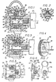
- the driver 28 comprises a hollow cylinder 34; here we mean by hollow cylinder a kind of sleeve or sheath; an axial end of the hollow cylinder 34 is in axial abutment against a hub 40 while being centered by an annular bearing 53 presented by the hub 40, engaged on the shaft 21 until it abuts axially against a bearing surface 25, for example conical, which presents the shaft 21; between the bearing 25 and the end of the shaft 21, in the outer wall thereof are provided grooves longitudinal 51; the internal bore through which the hub 40 is mounted on the end of the shaft 21 is provided with longitudinal grooves 52 cooperating with longitudinal grooves 51 formed on the outer surface of the end of said shaft centering the hub 40 which itself centers the cylinder hollow 34 thanks to its range 53.
- the range 25 of the shaft 21 is provided with grooves which extend the grooves 51 and which cooperate with corresponding grooves in the hub 40 extending in the same way its grooves 52.
- the end of the shaft 21 is hollow; it has a female thread 57 which opens out through a smooth bore 58 located axially in front of the scope 25; the smooth bore 58 is of larger diameter than that of the internal thread 57 and its outlet end is flared.
- the internal thread 57 is adapted to receive an additional thread 60 provided at the outer periphery of the end of the tail 62 with a screw support 61 having a head 63 hollowed out with a polygonal bore 65 for the screw operation 61.
- the head 63 of the screw 61 is in the form of a collar and is adapted to cooperate by its rear face 66 with a retaining washer 70 itself adapted to cooperate with the front face 35 of the hollow cylinder 34; when the screw 61 is mounted tightly in the shaft 21, the retaining washer 70 is at axial distance from the end of the shaft 21 so that the hollow cylinder then 34 is pressed against the hub 40 itself in axial support on the shaft 21.
- the front face 35 of the hollow cylinder 34 is bordered by an annular rim 59 to center the retaining washer 70 by its outer periphery; the retaining washer 70 supports centered the screw holding 61 which has a cylindrical bearing surface 67, of diameter less than that of the head 63 but larger than that of the tail 62, with which cooperates the central bore 73 of the retaining washer 70.
- the radial space existing between the end of the shaft 21 and the cylinder hollow 34 is used to make a device for adjusting the position relative angular of the hollow cylinder 34 and the shaft 21.
- the inner surface portions of the hollow cylinder 34 included between the grooves 36 carry a helical thread 29 of small pitch with which cooperates the corresponding external thread 56 of an annular screw of control 55 coupled in translation to the ring 80 by means of a heel 94 which it has and which is housed in an annular groove 85 of the ring 80.
- the groove 85 is cut annularly; it could, of course, for example facilitate obtaining by molding the ring 80, be materialized by stops transverse, front and rear, successively offset circumferentially.
- the displacement angle of the coach 28 with respect to the shaft 21 is obtained by making turn the annular control screw 55; to do this, it presents frontally one (or more) radial notch (s) 95, for example three radial notches 95 to 120 degrees, intended to receive the end of the feet 91 of an adjustment key 90, visible in Figure 4, consisting of disc 93 to which feet 91 are perpendicular and which comprises in its center a square hole 92 intended to receive the square end of a tool maneuver if necessary; as shown in dashed lines on the Figure 3, the correct positioning of the key 90, in particular the end of the feet 91 in the notches 95, is facilitated by the fact that the head 63 of the screw 61 has a peripheral cylindrical surface whose diameter is such that it fits perfectly into the volume embraced by the adjustment feet 91 and that when these are placed in line with the head 63 parallel to its axis they are radially in line with the notches 95; of course the washer holding 70 has openings 74 to 120 degrees for
- the ring ring 80 and its annular control screw 55 having been installed at inside the hollow cylinder 34, the ring 80 being in the axial position average with respect to the grooves 36, as shown in FIG. 1, the hub 40, the washer 70 and the screw 61 are put in place and maintained by a stirrup 96 elastic axial, for example of plastic, urging one towards the other axially the hub 40 and the head 63 of the screw 60 on which it takes support; head 63 positions it transversely along two planes perpendicular.
- a passage 97 in the stirrup 96 makes it possible to thread the assembly thus formed on the tree 21. We thus have a set ready to be mounted on the shaft 21, the thread 60 appearing outside the stirrup 96 and serving as a pilot for mounting the assembly on the shaft 21.
- the stirrup 96 is removed: a slot 99 opening into the passage 97 allows this removal; advantageously, the slot 99 has a smaller width to the diameter of the shaft 21 to avoid its accidental fall.
- the washer 70 has a certain elasticity; it can be slightly tapered at rest and flat after Tightening ; in this case, the scope 35 is flat; of course the reverse is also possible, the bearing surface 35 then being conical at an angle which corresponds to that of the washer 70 deformed after tightening.
- a transverse stop 36A limits the axial stroke of the annular screw 55; according to the embodiment shown in the figures, the stop 36A is the bottom axial grooves 36 provided in the form of blind grooves; in variant, the stop 36A is eliminated and it is the thread 29 itself which ensures the end of travel of the annular screw 55.
- FIG. 5 shows the device of FIGS. 1 to 3, on a smaller scale, otherwise pre-assembled; here, the yoke 96 is replaced by a breakable nut 216, for example made of plastic, mounted on the thread 60 of the screw maintenance 61; the assembly constituted by the retaining washer 70, the cylinder hollow 34 and the hub 40 is thus held axially between the head 63 of the retaining screw 61 and the breakaway nut 216; this includes bloodletting radial 217, for example three radial grooves distributed circumferentially, providing breakable zones 218; the breakable nut 216 has a conical inlet 221 so that when the assembly is presented in front of the shaft 21 and pushed towards the latter, the end of the said shaft 21 breaks, here in three segments, the breakable nut 216 due to this entry conical 221; it then suffices to screw the retaining screw 61.
- a breakable nut 216 for example made of plastic
- the pre-assembly is carried out by a stirrup 196, here transverse, for example made of plastic, in the form of a plate, comprising two wings 201, 202 defining a notch 203 whose bottom is circular, of diameter equal to the diameter at the bottom of the thread of the thread 60 of the retaining screw 61, and the inlet of which is less than said diameter in width ; at its end opposite to that which presents the notch 203, the stirrup transverse 196 has a gripping means, here a ring 204; so, the assembly is held axially between the head of the retaining screw 61 and the transverse stirrup 196 clipped onto the thread 60 of said screw; after introduction of the end of the thread 60 into the shaft 21, it suffices to remove radially the transverse stirrup 196, thanks to the ring 204, and to tighten the screw holding 61.
- a stirrup 196 here transverse, for example made of plastic, in the form of a plate, comprising two wings
- the annular ring 80 is provided, on the one hand, on its inner surface with helical grooves allowing it to be secured in rotation to said audit shaft while being axially movable and, on the other hand, on its surface exterior of at least one tooth with straight flanks or an inverted pitch, the cylinder hollow having at least one groove hollowed out on its inner surface and intended to receive said at least one tooth of the annular ring, the sides of said groove being straight or of inverted pitch and in correspondence with the straight or reverse flanks of said at least one tooth of the ring annular.
Landscapes
- Engineering & Computer Science (AREA)
- General Engineering & Computer Science (AREA)
- Mechanical Engineering (AREA)
- Chemical & Material Sciences (AREA)
- Combustion & Propulsion (AREA)
- Transmission Devices (AREA)
- Pulleys (AREA)
- Mutual Connection Of Rods And Tubes (AREA)
- Steering Controls (AREA)
Claims (17)
- Untereinheit, umfassend eine Kupplungsvorrichtung zum Ankuppeln an eine Welle (21), die dazu bestimmt ist, am Ende dieser Welle (21) angeordnet zu werden, wobei diese Vorrichtung einen Hohlzylinder (34) aufweist, der dazu bestimmt ist, die Welle (21) zu umgeben, einen Ring (80), der von dem Hohlzylinder (34) umgeben ist und axial beweglich ist, indem er dafür ausgelegt ist, bei dieser axialen Bewegung die Relativwinkelstellung zwischen dem Hohlzylinder (34) und der Welle (21) einzustellen, wobei eine Halteschraube (61) und eine Haltescheibe (70), die auf die Achse (20) der Welle (21) zentriert sind, vorgesehen sind, um, wenn die Vorrichtung auf der Welle (21) montiert ist, die Blockierung des Hohlzylinders (34) und der Welle (21) in ihrer eingestellten Relativwinkelstellung zu gewährleisten, dadurch gekennzeichnet, daß die Untereinheit ferner eine Nabe (40) aufweist, die dazu bestimmt ist, auf der Welle (21) montiert und axial blockiert zu werden, wobei diese Blockierung axial mit Hilfe der Halteschraube (61) die Haltescheibe (70) an die Vorderseite (35) des Hohlzylinders (34) und den Hohlzylinder (34) an die Nabe (40) andrückt, wobei Verbindungsmittel vorgesehen sind, um die Kupplungsvorrichtung und die Haltescheibe (70) mindestens vor der Montage der Kupplungsvorrichtung an der Welle zu verbinden, so daß die Kupplungsvorrichtung und die Haltescheibe Teil der Untereinheit bilden, wobei diese Verbindungsmittel aus einem Bügel (96, 196) bestehen.
- Untereinheit nach Anspruch 1, dadurch gekennzeichnet, daß die Verbindungsmittel auch die Halteschraube (61) verbinden.
- Untereinheit nach einem der Ansprüche 1 oder 2, dadurch gekennzeichnet, daß der Bügel (96) axial ist.
- Untereinheit nach einem der Ansprüche 1 oder 2, dadurch gekennzeichnet, daß der Bügel (196) sich quer erstreckt.
- Untereinheit nach einem der Ansprüche 1 bis 4, dadurch gekennzeichnet, daß der Ring (80) einerseits an seiner Innenfläche mit Längsnuten (81), die es ihm gestatten, bezüglich Drehung mit der Welle (21) fest verbunden zu sein, wobei er gleichzeitig axial beweglich ist, und andererseits an seiner Außenfläche mit mindestens einem Zahn (82) mit schraubenförmigen Flanken (83, 84) versehen ist, wobei der Hohlzylinder (34) mindestens eine auf seiner Innenfläche ausgesparte Nut (36) aufweist, die dazu bestimmt ist, diesen mindestens einen Zahn (82) des Rings (80) aufzunehmen, wobei die Flanken (38, 39) der Nut (36) schraubenförmig und in Entsprechung mit den schraubenförmigen Flanken (83, 84) dieses mindestens einen Zahns (82) des Rings (80) sind.
- Untereinheit nach einem der Ansprüche 1 bis 4, dadurch gekennzeichnet, daß der Ring einerseits an seiner Innenfläche mit schraubenförmigen Nuten versehen ist, die es ihm gestatten, bezüglich Drehung mit der Welle fest verbunden zu sein, wobei er gleichzeitig axial beweglich ist, und andererseits an seiner Außenfläche mit mindestens einem Zahn mit geraden Flanken oder Flanken mit umgekehrter Steigung versehen ist, wobei der Hohlzylinder mindestens eine auf seiner Innenfläche ausgesparte Nut aufweist, die dazu bestimmt ist, diesen mindestens einen Zahn des Rings aufzunehmen, wobei die Flanken der Nut gerade oder von umgekehrter Steigung und in Entsprechung mit den geraden Flanken oder den Flanken mit umgekehrter Steigung dieses mindestens eines Zahns des Rings sind.
- Untereinheit nach einem der Ansprüche 1 bis 6, dadurch gekennzeichnet, daß für die axiale Bewegung des Rings (80) eine ringförmige Antriebsschraube (55) ein schraubenförmiges Gewinde (56) trägt, das mit einem schraubenförmigen Gewinde (29) zusammenwirkt, das in seiner außerhalb der Nut (36) gelegenen Zone auf der Fläche des Teils, Hohlzylinder (34) oder Nabe (40), vorgesehen ist, das die mindestens eine Nut (36) trägt, wobei der Ring (80) bezüglich Translation mit der ringförmigen Antriebsschraube (55) gekoppelt ist.
- Untereinheit nach Anspruch 7, dadurch gekennzeichnet, daß ein Queranschlag (36A) den axialen Hub der ringförmigen Schraube (55) begrenzt.
- Untereinheit nach einem der Ansprüche 7 oder 8, dadurch gekennzeichnet, daß die ringförmige Schraube (55) im Ruhezustand nicht vollkommmen kreisförmig ist.
- Untereinheit nach einem der Ansprüche 7 bis 9, dadurch gekennzeichnet, daß die ringförmige Schraube (55) geschlitzt ist und ihr Gewinde (56) ein einziges Gewinde ist, das auf einer Seite des Schlitzes beginnt und auf der anderen Seite endet.
- Untereinheit nach einem der Ansprüche 1 bis 10, dadurch gekennzeichnet, daß die Haltescheibe (70) im Ruhezustand leicht konisch ist und nach dem Anziehen eben ist.
- Untereinheit nach einem der Ansprüche 1 bis 10, dadurch gekennzeichnet, daß die Haltescheibe (70) im Ruhezustand eben ist und nach dem Anziehen leicht konisch ist, wobei die Vorderseite (35) des Hohlzylinders (34) leicht konisch ist.
- Untereinheit nach einem der Ansprüche 1 bis 12, dadurch gekennzeichnet, daß die Haltescheibe (70) mindestens eine Öffnung (74) für das Einsetzen eines Stellwerkzeugs (90) aufweist.
- Untereinheit nach einem der Ansprüche 1 bis 13, dadurch gekennzeichnet, daß die in Kontakt befindlichen Flächen der Teile zur Erhöhung des von der Auflagefläche des Hohlzylinders (34) auf die Nabe (40) übertragenen Antriebsmoments so behandelt sind, daß die Reibung erhöht ist.
- Welle und Untereinheit, wobei die Welle am Ende mit einer Kupplungsvorrichtung ausgerüstet ist, die Teil dieser Untereinheit bildet, dadurch gekennzeichnet, daß die Untereinheit gemäß einem der Ansprüche 1 bis 14 ausgeführt ist, wobei die Nabe (40) der Kupplungsvorrichtung in einer vorbestimmten Winkelstellung gegen Drehung bezüglich der Welle (21) blockiert ist.
- Welle und Untereinheit nach Anspruch 15, dadurch gekennzeichnet, daß die axiale Blockierung der Nabe (40) durch eine Auflagefläche (25) der Welle (21) bewirkt wird, die mit Nuten versehen ist, die die Nuten (51) der Welle (21) verlängern und die mit entsprechenden Nuten der Nabe (40) zusammenwirken, die in derselben Weise ihre Nuten (52) verlängern.
- Welle und Untereinheit nach einem der Ansprüche 15 oder 16, dadurch gekennzeichnet, daß die Untereinheit ein Mitnehmer (28) eines Scheibenwischerarms ist, wobei dieser Mitnehmer den Hohlzylinder (34) umfaßt.
Applications Claiming Priority (3)
| Application Number | Priority Date | Filing Date | Title |
|---|---|---|---|
| FR9506895 | 1995-06-12 | ||
| FR9506895A FR2735193B1 (fr) | 1995-06-12 | 1995-06-12 | Dispositif d'accouplement d'un cylindre creux a un arbre, destine a etre place en bout dudit arbre, la position angulaire relative du cylindre et de l'arbre etant reglable |
| PCT/FR1996/000880 WO1996041963A1 (fr) | 1995-06-12 | 1996-06-11 | Dispositif d'accouplement reglable |
Publications (2)
| Publication Number | Publication Date |
|---|---|
| EP0832369A1 EP0832369A1 (de) | 1998-04-01 |
| EP0832369B1 true EP0832369B1 (de) | 2003-01-08 |
Family
ID=9479844
Family Applications (1)
| Application Number | Title | Priority Date | Filing Date |
|---|---|---|---|
| EP96922093A Expired - Lifetime EP0832369B1 (de) | 1995-06-12 | 1996-06-11 | Einstellbare kupplungsvorrichtung |
Country Status (7)
| Country | Link |
|---|---|
| US (1) | US6135664A (de) |
| EP (1) | EP0832369B1 (de) |
| JP (1) | JPH11507716A (de) |
| KR (1) | KR19990022883A (de) |
| DE (1) | DE69625689D1 (de) |
| FR (1) | FR2735193B1 (de) |
| WO (1) | WO1996041963A1 (de) |
Families Citing this family (5)
| Publication number | Priority date | Publication date | Assignee | Title |
|---|---|---|---|---|
| DE19938443A1 (de) * | 1999-08-13 | 2001-02-15 | Abb Alstom Power Ch Ag | Befestigungs- und Fixierungsvorrichtung |
| RU2221937C1 (ru) * | 2002-07-17 | 2004-01-20 | Федеральное государственное унитарное предприятие Государственный научный центр Российской Федерации "Научно-исследовательский институт атомных реакторов" | Устройство точного совмещения концевых угловых положений сопрягаемых валов |
| US7043858B2 (en) * | 2004-04-27 | 2006-05-16 | Cnh America Llc | Backhoe pivot joint |
| JP4407754B2 (ja) * | 2008-01-29 | 2010-02-03 | 株式会社デンソー | ポンプ |
| EP2759710A1 (de) * | 2013-01-23 | 2014-07-30 | Sulzer Pumpen AG | Zentrifugalpumpe und Hülse zum Kuppeln der Welle einer Zentrifugalpumpe mit der Welle eines Antriebsmotors |
Family Cites Families (15)
| Publication number | Priority date | Publication date | Assignee | Title |
|---|---|---|---|---|
| US1903162A (en) * | 1930-01-17 | 1933-03-28 | Bosch Robert | Shaft coupling |
| DE900505C (de) * | 1943-11-06 | 1953-12-28 | Bosch Gmbh Robert | Spritzbeginn- oder Zuendzeitpunkt-Versteller fuer Brennkraftmaschinen |
| FR2557992B1 (fr) * | 1984-01-06 | 1986-11-07 | Eckendorff Jean Pierre | Dispositif pour regler la position angulaire d'un organe cale en rotation avec un arbre, notamment volant de vehicule automobile associe a une colonne de direction. |
| JPS61105326A (ja) * | 1984-10-29 | 1986-05-23 | Honda Motor Co Ltd | フライホイ−ルのクランクシヤフトへの結合構造 |
| FR2607564B1 (fr) * | 1986-12-02 | 1990-12-21 | Eckendorff Jean Pierre | Systeme d'assemblage d'un element menant tel que le moyeu d'un volant de vehicule automobile accouple en rotation a un element mene tel qu'une colonne de direction |
| FR2611835B1 (fr) * | 1987-02-23 | 1990-12-21 | Eckendorff Jean Pierre | Systeme d'assemblage d'un element menant tel que le moyeu d'un volant de vehicule automobile accouple en rotation a un element mene tel qu'une colonne de direction |
| FR2625711B1 (fr) * | 1988-01-12 | 1992-04-24 | Peugeot | Dispositif de suspension hydropneumatique semi-active et vehicule automobile equipe de ce dispositif |
| EP0420840A1 (de) * | 1988-06-02 | 1991-04-10 | ECKENDORFF, Jean-Pierre | Zusammenbau eines treibenden teiles, das gekuppelt ist mit einem getriebenen teil |
| JP2833128B2 (ja) * | 1990-03-29 | 1998-12-09 | アイシン精機株式会社 | 弁開閉時期制御装置 |
| US5094117A (en) * | 1990-12-26 | 1992-03-10 | Chrysler Corporation | Infinitely adjustable bolt locking plate |
| US5141090A (en) * | 1991-09-25 | 1992-08-25 | Ogura Corporation | Electromagnetic clutch |
| US5356236A (en) * | 1991-09-25 | 1994-10-18 | Turbomeca | Device for connecting two elements in rotation |
| FR2689584A1 (fr) * | 1992-04-07 | 1993-10-08 | Renault | Dispositif de calage de la position angulaire d'un moyeu de volant de direction. |
| US5308183A (en) * | 1992-07-09 | 1994-05-03 | General Motors Corporation | Lock coupling between shaft and rotor |
| FR2699483B1 (fr) * | 1992-12-23 | 1995-02-10 | Journee Paul Sa | Essuie-glace de véhicule automobile comportant des moyens de réglage de l'orientation de la lame d'essuyage. |
-
1995
- 1995-06-12 FR FR9506895A patent/FR2735193B1/fr not_active Expired - Fee Related
-
1996
- 1996-06-11 EP EP96922093A patent/EP0832369B1/de not_active Expired - Lifetime
- 1996-06-11 DE DE69625689T patent/DE69625689D1/de not_active Expired - Lifetime
- 1996-06-11 WO PCT/FR1996/000880 patent/WO1996041963A1/fr not_active Ceased
- 1996-06-11 US US08/973,238 patent/US6135664A/en not_active Expired - Fee Related
- 1996-06-11 JP JP9502702A patent/JPH11507716A/ja active Pending
- 1996-06-11 KR KR1019970709352A patent/KR19990022883A/ko not_active Withdrawn
Also Published As
| Publication number | Publication date |
|---|---|
| JPH11507716A (ja) | 1999-07-06 |
| FR2735193A1 (fr) | 1996-12-13 |
| FR2735193B1 (fr) | 1997-08-22 |
| KR19990022883A (ko) | 1999-03-25 |
| US6135664A (en) | 2000-10-24 |
| WO1996041963A1 (fr) | 1996-12-27 |
| DE69625689D1 (de) | 2003-02-13 |
| EP0832369A1 (de) | 1998-04-01 |
Similar Documents
| Publication | Publication Date | Title |
|---|---|---|
| EP0336833B1 (de) | Einstellbarer Anschlag | |
| EP2496849B1 (de) | Selbstblockierende schraubfixiervorrichtung und anordnung damit | |
| EP1181176B1 (de) | Vorrichtung zum befestigen einer wischerarmnabe auf einer drehachse | |
| EP1815926A2 (de) | Werkzeughalter-Dorn für die Ausstattung einer elektrisch umlaufenden Maschine | |
| EP0669237B1 (de) | Scheibenwischer mit verbesserten Verbindungsmitteln zwischen der Antriebswelle und dem Befestigungsteil | |
| FR2487455A1 (fr) | Dispositif de fixation filete difficilement alterable | |
| EP0832369B1 (de) | Einstellbare kupplungsvorrichtung | |
| WO1999019598A1 (fr) | Accouplement pour dispositif a transmission de forces | |
| EP0102898B1 (de) | Mutter mit automatischer positiver Sicherung | |
| CA2578805A1 (fr) | Tete a aleser | |
| EP0491603B1 (de) | Verbindungsglied zwischen einem Scheibenwischerarm, insbesondere für Kraftfahrzeug | |
| FR2793429A1 (fr) | Mandrin pour appareil d'entrainement comportant une broche rotative | |
| EP2110573B1 (de) | Vorrichtung zur Schnelldemontage der kompletten Blockiervorrichtung auf der Welle einer Riemenscheibe | |
| EP2221494A1 (de) | Vorrichtung zur Fixierung eines Radiallagers einer Getriebewelle eines Kraftfahrzeuges | |
| EP0079291B1 (de) | Sicherheitsmutterpaar mit doppelter Sicherung | |
| FR2729905A1 (fr) | Dispositif d'essuie-glace comportant des moyens perfectionnes de demontage de sa tete d'entrainement | |
| FR2679304A1 (fr) | Dispositif d'assemblage d'une piece avec un axe, notamment pour un dispositif d'essuie-glace. | |
| FR2935664A1 (fr) | Systeme de direction en particulier pour vehicule automobile, comprenant un arbre de direction s'emboitant dans un percage d'un moyeu d'un volant | |
| FR3050494A1 (fr) | Vis a faibles pertes de matiere pour systeme de freinage de vehicule | |
| FR2954249A1 (fr) | Dispositif d'essuie-glace notamment de vehicule automobile | |
| EP0857608B1 (de) | Kraftfahrzeugscheinwerfer mit Einstellung der Orientierung des Lichtbündels | |
| FR2607564A1 (fr) | Systeme d'assemblage d'un element menant tel que le moyeu d'un volant de vehicule automobile accouple en rotation a un element mene tel qu'une colonne de direction | |
| FR2914578A1 (fr) | Outil debrayable permettant d'entrainer simultanement une vis et un ecrou | |
| FR2648381A1 (fr) | Outil pour le montage et le demontage d'agrafes d'epinglage | |
| WO1997025236A1 (fr) | Volant de direction et colonne adaptee au montage d'un tel volant |
Legal Events
| Date | Code | Title | Description |
|---|---|---|---|
| PUAI | Public reference made under article 153(3) epc to a published international application that has entered the european phase |
Free format text: ORIGINAL CODE: 0009012 |
|
| 17P | Request for examination filed |
Effective date: 19971204 |
|
| AK | Designated contracting states |
Kind code of ref document: A1 Designated state(s): DE ES FR GB IT |
|
| 17Q | First examination report despatched |
Effective date: 20001127 |
|
| GRAG | Despatch of communication of intention to grant |
Free format text: ORIGINAL CODE: EPIDOS AGRA |
|
| GRAG | Despatch of communication of intention to grant |
Free format text: ORIGINAL CODE: EPIDOS AGRA |
|
| GRAH | Despatch of communication of intention to grant a patent |
Free format text: ORIGINAL CODE: EPIDOS IGRA |
|
| GRAH | Despatch of communication of intention to grant a patent |
Free format text: ORIGINAL CODE: EPIDOS IGRA |
|
| GRAA | (expected) grant |
Free format text: ORIGINAL CODE: 0009210 |
|
| AK | Designated contracting states |
Kind code of ref document: B1 Designated state(s): DE ES FR GB IT |
|
| PG25 | Lapsed in a contracting state [announced via postgrant information from national office to epo] |
Ref country code: IT Free format text: LAPSE BECAUSE OF FAILURE TO SUBMIT A TRANSLATION OF THE DESCRIPTION OR TO PAY THE FEE WITHIN THE PRESCRIBED TIME-LIMIT;WARNING: LAPSES OF ITALIAN PATENTS WITH EFFECTIVE DATE BEFORE 2007 MAY HAVE OCCURRED AT ANY TIME BEFORE 2007. THE CORRECT EFFECTIVE DATE MAY BE DIFFERENT FROM THE ONE RECORDED. Effective date: 20030108 Ref country code: GB Free format text: LAPSE BECAUSE OF FAILURE TO SUBMIT A TRANSLATION OF THE DESCRIPTION OR TO PAY THE FEE WITHIN THE PRESCRIBED TIME-LIMIT Effective date: 20030108 |
|
| REG | Reference to a national code |
Ref country code: GB Ref legal event code: FG4D Free format text: NOT ENGLISH |
|
| REF | Corresponds to: |
Ref document number: 69625689 Country of ref document: DE Date of ref document: 20030213 Kind code of ref document: P |
|
| PG25 | Lapsed in a contracting state [announced via postgrant information from national office to epo] |
Ref country code: DE Free format text: LAPSE BECAUSE OF FAILURE TO SUBMIT A TRANSLATION OF THE DESCRIPTION OR TO PAY THE FEE WITHIN THE PRESCRIBED TIME-LIMIT Effective date: 20030409 |
|
| GBV | Gb: ep patent (uk) treated as always having been void in accordance with gb section 77(7)/1977 [no translation filed] |
Effective date: 20030108 |
|
| PG25 | Lapsed in a contracting state [announced via postgrant information from national office to epo] |
Ref country code: ES Free format text: LAPSE BECAUSE OF FAILURE TO SUBMIT A TRANSLATION OF THE DESCRIPTION OR TO PAY THE FEE WITHIN THE PRESCRIBED TIME-LIMIT Effective date: 20030730 |
|
| PLBE | No opposition filed within time limit |
Free format text: ORIGINAL CODE: 0009261 |
|
| STAA | Information on the status of an ep patent application or granted ep patent |
Free format text: STATUS: NO OPPOSITION FILED WITHIN TIME LIMIT |
|
| 26N | No opposition filed |
Effective date: 20031009 |
|
| REG | Reference to a national code |
Ref country code: FR Ref legal event code: ST Effective date: 20080229 |
|
| PGFP | Annual fee paid to national office [announced via postgrant information from national office to epo] |
Ref country code: FR Payment date: 20061230 Year of fee payment: 11 |
|
| PG25 | Lapsed in a contracting state [announced via postgrant information from national office to epo] |
Ref country code: FR Free format text: LAPSE BECAUSE OF NON-PAYMENT OF DUE FEES Effective date: 20070702 |