EP0833023A2 - Schliesszylinder mit einer Überlastkupplungseinrichtung - Google Patents
Schliesszylinder mit einer Überlastkupplungseinrichtung Download PDFInfo
- Publication number
- EP0833023A2 EP0833023A2 EP97112892A EP97112892A EP0833023A2 EP 0833023 A2 EP0833023 A2 EP 0833023A2 EP 97112892 A EP97112892 A EP 97112892A EP 97112892 A EP97112892 A EP 97112892A EP 0833023 A2 EP0833023 A2 EP 0833023A2
- Authority
- EP
- European Patent Office
- Prior art keywords
- cylinder
- rocker
- driver
- housing
- overload
- Prior art date
- Legal status (The legal status is an assumption and is not a legal conclusion. Google has not performed a legal analysis and makes no representation as to the accuracy of the status listed.)
- Ceased
Links
Images

Classifications
-
- E—FIXED CONSTRUCTIONS
- E05—LOCKS; KEYS; WINDOW OR DOOR FITTINGS; SAFES
- E05B—LOCKS; ACCESSORIES THEREFOR; HANDCUFFS
- E05B17/00—Accessories in connection with locks
- E05B17/04—Devices for coupling the turning cylinder of a single or a double cylinder lock with the bolt operating member
-
- E—FIXED CONSTRUCTIONS
- E05—LOCKS; KEYS; WINDOW OR DOOR FITTINGS; SAFES
- E05B—LOCKS; ACCESSORIES THEREFOR; HANDCUFFS
- E05B17/00—Accessories in connection with locks
- E05B17/0054—Fraction or shear lines; Slip-clutches, resilient parts or the like for preventing damage when forced or slammed
Definitions
- the invention relates to a locking cylinder with the in the preamble of claim 1 specified features.
- Such a locking cylinder is for example from DE 40 41 134 C1 and known from EP 0 611 860 A1. It embraces a housing with a rotatably arranged in the housing, a key channel cylinder core, which at Withdrawal of a key from the key channel via tumblers with one arranged between the housing and the cylinder core Cylinder liner can be locked. There is also an overload clutch device provided so that when turning of the cylinder core with an improper one Key or tool the output element connected to the lock is uncoupled from the cylinder core.
- the overload clutch device consists of at least one radial slidably and non-rotatably connected to the cylinder core Driver, which is located radially outward on the output element supports and in a driving groove of the output element intervenes, as well as one interacting with the driver in the event of an overload Control.
- the latter is around a plunger, which is provided in a control surface Radial recess of the housing is supported and by rotation the cylinder liner is pressed out of the radial recess and the driver moves radially.
- a disadvantage of the known lock cylinder is i.a. the relatively complex control of the driver in the event of an overload.
- DE 692 00 617 T2 discloses a locking cylinder with an in a housing arranged cylinder core and a cylinder liner known.
- the cylinder liner rotates when the cylinder core rotates, the cylinder liner has radially extending legs which, in the event of an overload, in corresponding recesses of the Cylinder core are pressed and take the cylinder liner cause.
- the radial legs of the cylinder liner are key however, pressed into a recess in the housing, so that the cylinder liner does not move when the cylinder core rotates can move.
- DE 694 00 327 T2 discloses a further development of DE 692 00 617 T2, with the radial legs of the cylinder liner be replaced by at least one separate lever that with its first end in a corresponding recess of the Cylinder liner can be used and, depending on the condition of the Lock cylinder, with its second end in one Recess of the cylinder core or in a recess of the Engages housing.
- the invention has for its object a locking cylinder of the type mentioned at the beginning, in which the with the Driver interacting control element in the event of an overload radial and easy displacement of the driver causes.
- the invention is essentially based on the idea that Control to use a rocker-shaped element, which rotatably and around a arranged on the cylinder liner Cutting edge is pivotally mounted, which is the driver first end of the rocker facing away in the event of an overload with a extending in the circumferential direction of the cylinder liner Control slope is engaged so that when turning the cylinder liner about its longitudinal axis this end of the Rocker swiveled towards the housing and the second end of the Seesaw, which is on the end of the driver facing him supports this radially against the pressure of a spring pushes inwards.
- the output element of the Cylinder core mechanically decoupled, so that the torque transmission interrupted by the key to the output element is.
- the rocker on its side facing away from the cylinder liner at least one locking element, which in the event of an overload engages a corresponding recess of the output element. This will result in a possible rotational movement of the output element and the mechanical fasteners between Output element and lock blocked. A manipulation of in this case, the back of the lock cylinder leads to no unlocking movement of the connected to the lock cylinder Castle.
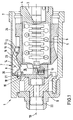
- 1 is a lock cylinder, e.g. for a locking system the car door of a motor vehicle.
- the Lock cylinder 1 contains a rotatable in a housing 2 arranged, a key channel 3 having cylinder core 4.
- the cylinder core 4 is in the locked state of the lock cylinder 1 via tumblers 5 with a between Housing 2 and cylinder core 4 arranged cylinder liner 6 non-positively connected.
- the overload clutch 7 contains a control element 9, which as a seesaw-shaped, in the direction of the longitudinal axis 10 of the Lock cylinder 1 extending element (rocker) is formed is.
- the rocker 9 is non-rotatably in the housing 2 and by one the cylinder liner 6 arranged and towards the housing 2 extending cutting edge 11 pivotally mounted.
- the first end 12 of the rocker 9 stands with an overload extending in the circumferential direction of the cylinder liner 6 Control bevels 13 in engagement, such that upon rotation the cylinder liner 6 about its longitudinal axis 10 this end 12 of the Rocker 9 pivoted towards the housing 2 and the second end 14 the rocker 9, which is at the corresponding end 15 of a radially displaceable driver 16 which rotatably with the Cylinder core 4 is connected, supports this against the Pressure of a spring 17 presses radially inwards (Fig. 2). Thereby becomes an outside on the output element 8 itself supporting nose-shaped projection 18 from a corresponding Recess 19 pressed and the connection between Cylinder core 4 and output element 8 released.
- the rocker 9 is at its second end 14 as a locking element 20th trained, which in the event of overload in a corresponding Recess 21 of the output element 8 engages. This will a possible rotational movement of the output element 8 and a mechanical connecting element 22 between the output element 8 and not shown lock blocked. A Manipulation from the back of the lock cylinder leads to In this case, no unlocking movement of the with Lock cylinder 1 connected lock.
- the driver 16 is designed such that between the second end 14 of the rocker 9 and that facing the rocker End 15 of the driver 16 remains a gap-shaped opening 23.
- the lock cylinder should 1 are in the normal position shown in Fig.1.
- a suitable key is inserted into key channel 3 and a torque is initiated, the tumblers 5 from the corresponding recesses in the cylinder liner 6 pulled out. A rotation of the cylinder core 4 in the bush 6 is now possible.
- the nose-shaped projection 18 of the driver 16 engages in the recess 19 provided therefor Output element 8 and transmits the necessary for opening Rotational movement on the non-rotatable with the output element 8 connected connecting element 22 to the door lock.
- the second end 14 of the rocker 9 controls after overcoming the gap-shaped opening 23 (Fig.1) the driver 16 to the inside.
- the projection 18 of the driver 16 is made from the recess 19 of the output element 8 pulled out (Fig.2).
- the locking element 20 dips into the recess 21 of the output element 8 and blocks its possible rotational movement.
- the mechanical connecting element 22 between Output element 8 and door lock, not shown, is thus blocked in its position.
- the invention is of course not based on the above described embodiment limited.
- just one driver between the cylinder core and output element also several distributed over the circumference Carrier can be used.
- Several can be used per carrier Detent elements are provided, which in corresponding recesses of the output element.
Landscapes
- Lock And Its Accessories (AREA)
- One-Way And Automatic Clutches, And Combinations Of Different Clutches (AREA)
- Transmission Devices (AREA)
Abstract
Description
- Fig.1
- einen Längsschnitt durch einen in Normallage befindlichen erfindungsgemäßen Schließzylinder mit Überlastkupplung und
- Fig.2
- den Fig.1 entsprechenden Längsschnitt des Schließzylinders, wobei sich die Überlastkupplung in ihrer Freilauflage (Überlastfall) befindet.
- 1
- Schließzylinder
- 2
- Gehäuse
- 3
- Schlüsselkanal
- 4
- Zylinderkern
- 5
- Zuhaltung
- 6
- Zylinderbuchse
- 7
- Überlast-Kupplungseinrichtung
- 8
- Abtriebselement
- 9
- Steuerelement, wippenförmiges Element, Wippe
- 10
- Längsachse
- 11
- Schneide
- 12
- erste Ende
- 13
- Steuerschräge
- 14
- zweite Ende
- 15
- Ende (Mitnehmer)
- 16
- Mitnehmer
- 17
- Feder
- 18
- nasenförmiger Vorsprung
- 19
- Aussparung
- 20
- Rastelement
- 21
- Ausnehmung
- 22
- Verbindungselement
- 23
- spaltförmige Öffnung
- 24
- Gehäuseausnehmung, Ausnehmung
Claims (4)
- Schließzylinder mit einem in einem Gehäuse (2) drehbar angeordneten, einen Schlüsselkanal (3) aufweisenden Zylinderkern (4), der nach Abzug eines Schlüssels aus dem Schlüsselkanal (3) über Zuhaltungen (5) mit einer zwischen Gehäuse (2) und Zylinderkern (4) angeordneten Zylinderbuchse (6) verriegelbar ist, und der mit einer Überlast-Kupplungseinrichtung (7) ausgestattet ist, derart, daß bei Drehbetätigung des Zylinderkerns (4) mit einem nicht bestimmungsgemäßen Schlüssel oder Werkzeug die Drehmitnahme eines Abtriebselementes (8) von dem Zylinderkern (4) entkuppelt wird, wobei sich die Überlast-Kupplungseinrichtung (7) aus mindestens einem radial verschiebbaren und drehfest mit dem Zylinderkern (4) verbundenen Mitnehmer (16), der sich radial auswärts an dem Abtriebselement (8) abstützt und in jeweils mindestens eine Aussparung (19) des Abtriebselementes (8) eingreift, sowie einem mit dem Mitnehmer (16) im Überlastfall zusammenwirkenden Steuerelement (9) besteht, gekennzeichnet durch die Merkmale:a) das Steuerelement (9) ist als sich in Richtung der Längsachse (10) des Schließzylinders (1) erstreckende Wippe ausgebildet, welche in dem Gehäuse (2) drehfest und um eine an der Zylinderbuchse (6) angeordnete und sich zum Gehäuse (2) hin erstreckende Schneide (11) schwenkbar gelagert ist,b) das dem Mitnehmer (16) abgewandte erste Ende (12) der Wippe (9) steht im Überlastfall mit einer sich in Umfangsrichtung der Zylinderbuchse (6) erstreckenden Steuerschräge (13) im Eingriff, derart, daß bei einer Drehung der Zylinderbuchse (6) um ihre Längsachse (10) dieses Ende (12) der Wippe (9) zum Gehäuse (2) hin geschwenkt und das zweite Ende (14) der Wippe (9), welches sich an dem ihm zugewandten Ende (15) des Mitnehmers (16) abstützt, diesen gegen den Druck einer Feder (17) radial nach innen und aus der Aussparung (19) des Abtriebselementes (8) herausdrückt.
- Schließzylinder nach Anspruch 1, dadurch gekennzeichnet, daß die Wippe (9) auf ihrer der Zylinderbuchse (6) abgewandten Seite mindestens ein Rastelement (20) besitzt, welches im Überlastfall in eine entsprechende Ausnehmung (21) des Abtriebselementes (8) eingreift.
- Schließzylinder nach Anspruch 1 oder 2, dadurch gekennzeichnet, daß die Wippe (9) mindestens teilweise in einer Ausnehmung (24) des Gehäuses (2) angeordnet ist, und daß in der Normalstellung des Schließzylinders (1) zwischen dem zweiten Ende (14) der Wippe (9) und dem der Wippe zugewandten Ende (15) des Mitnehmers (16) eine spaltförmige Öffnung (23) verbleibt.
- Schließzylinder nach einem der Ansprüche 1 bis 3, dadurch gekennzeichnet, daß die Überlast-Kupplungseinrichtung (7) zwei radial gegenüberliegende Mitnehmer (16) umfaßt.
Applications Claiming Priority (2)
| Application Number | Priority Date | Filing Date | Title |
|---|---|---|---|
| DE19639248 | 1996-09-25 | ||
| DE1996139248 DE19639248C1 (de) | 1996-09-25 | 1996-09-25 | Schließzylinder |
Publications (2)
| Publication Number | Publication Date |
|---|---|
| EP0833023A2 true EP0833023A2 (de) | 1998-04-01 |
| EP0833023A3 EP0833023A3 (de) | 1998-09-16 |
Family
ID=7806771
Family Applications (1)
| Application Number | Title | Priority Date | Filing Date |
|---|---|---|---|
| EP97112892A Ceased EP0833023A3 (de) | 1996-09-25 | 1997-07-26 | Schliesszylinder mit einer Überlastkupplungseinrichtung |
Country Status (2)
| Country | Link |
|---|---|
| EP (1) | EP0833023A3 (de) |
| DE (1) | DE19639248C1 (de) |
Families Citing this family (6)
| Publication number | Priority date | Publication date | Assignee | Title |
|---|---|---|---|---|
| DE10015690A1 (de) * | 2000-03-29 | 2001-10-18 | Huf Huelsbeck & Fuerst Gmbh | Eine Überlastsperre aufweisende Verschlußvorrichtung für insbesondere an Fahrzeugen vollziehbare Schließfunktionen |
| DE10100787A1 (de) * | 2001-01-10 | 2002-07-11 | Winkhaus Fa August | Schliesszylinder |
| DE20203600U1 (de) | 2002-02-26 | 2003-01-16 | Bks Gmbh, 42549 Velbert | Schließzylinder |
| DE10326717B4 (de) * | 2003-06-06 | 2014-08-14 | Volkswagen Ag | Einrichtung zur Sicherung eines Kraftfahrzeuges vor unbefugtem Öffnen, insbesondere der Fahrzeugtür |
| DE102007023458A1 (de) | 2007-05-19 | 2008-11-20 | Huf Hülsbeck & Fürst Gmbh & Co. Kg | Schließzylinder für insbesondere in einem Fahrzeug ausführbare Funktionen |
| ITTO20110192A1 (it) * | 2011-03-03 | 2012-09-04 | Giobert Spa | Serratura provvista di un sistema anti-effrazione per una porta di un veicolo |
Family Cites Families (6)
| Publication number | Priority date | Publication date | Assignee | Title |
|---|---|---|---|---|
| DE4041134C1 (en) * | 1990-12-21 | 1992-06-04 | Huelsbeck & Fuerst Gmbh & Co Kg, 5620 Velbert, De | Car lock cylinder with core guide - which carriers a radially displaceable follower, spring-loaded up to radial abutment on guide |
| FR2678312B1 (fr) * | 1991-06-27 | 1995-09-15 | Valeo Securite Habitacle | Verrou a rotor debrayable. |
| DE4304873A1 (de) * | 1993-02-18 | 1994-08-25 | Ymos Ag Ind Produkte | Schließvorrichtung |
| FR2705387B1 (fr) * | 1993-05-21 | 1995-06-30 | Valeo Securite Habitacle | Verrou à rotor débrayable. |
| JPH084378A (ja) * | 1993-11-30 | 1996-01-09 | Tokai Rika Co Ltd | シリンダ錠装置 |
| FR2731456B1 (fr) * | 1995-03-10 | 1997-04-04 | Valeo Securite Habitacle | Verrou a rotor debrayable et antivol de direction de vehicule automobile equipe d'un tel verrou |
-
1996
- 1996-09-25 DE DE1996139248 patent/DE19639248C1/de not_active Expired - Fee Related
-
1997
- 1997-07-26 EP EP97112892A patent/EP0833023A3/de not_active Ceased
Also Published As
| Publication number | Publication date |
|---|---|
| EP0833023A3 (de) | 1998-09-16 |
| DE19639248C1 (de) | 1998-01-02 |
Similar Documents
| Publication | Publication Date | Title |
|---|---|---|
| EP0833024B1 (de) | Schliesszylinder | |
| DE69104464T2 (de) | Zylinderschloss. | |
| EP1727953B1 (de) | Schloss, insbesondere für fahrzeugtüren, -klappen oder dergleichen | |
| EP0752044B1 (de) | Verschlussvorrichtung mit einem schliesszylinder für insbesondere an kraftfahrzeugen vollziehbare schliessfunktion | |
| EP3015629B1 (de) | Kraftfahrzeugtürgriffanordnung mit unfallsicherung | |
| DE69918650T2 (de) | Zylinderschlossvorrichtung | |
| DE3827418C2 (de) | ||
| DE102019111936A1 (de) | Kraftfahrzeugtürschloss | |
| EP1025325B1 (de) | Verschlussvorrichtung mit einem schlüsselbetätigbaren schliesszylinder, der zugleich als druckhandhabe zum betätigen von schlossgliedern dient | |
| EP0887240B1 (de) | Verriegelungsvorrichtung für ein Kraftfahrzeug | |
| EP3784855B1 (de) | Kraftfahrzeugschloss | |
| DE4325693C2 (de) | Türschließeinrichtung | |
| DE69916122T2 (de) | Zylinderschloss | |
| DE69907311T2 (de) | Axial entkuppelndes Schloss für ein Schlossmechanismus eines Personenkraftwagens | |
| EP0833023A2 (de) | Schliesszylinder mit einer Überlastkupplungseinrichtung | |
| DE10301998B4 (de) | Schließhilfe zum Verschließen einer mit einem Türschloß versehenen Fahrzeugtür | |
| DE19639251C1 (de) | Schließzylinder | |
| EP1267022B1 (de) | Notverriegelungseinrichtung | |
| DE19959833C1 (de) | Schließvorrichtung für insbesondere an Fahrzeugen vollziehbare Schließfunktionen | |
| DE4339654C3 (de) | Kraftfahrzeugtürverschluß | |
| EP0791707B1 (de) | Kraftfahrzeugschloss | |
| EP0732241B1 (de) | Verriegelungsvorrichtung für Kraftfahrzeuge | |
| EP0681950B1 (de) | Vorrichtung mit einem Wählhebel für Kraftfahrzeug-Automatikgetriebe | |
| DE3110579A1 (de) | Zuendanlassschalter- und lenkungsschloss fuer kraftfahrzeuge | |
| EP1156179A2 (de) | Schliesszylinder |
Legal Events
| Date | Code | Title | Description |
|---|---|---|---|
| PUAI | Public reference made under article 153(3) epc to a published international application that has entered the european phase |
Free format text: ORIGINAL CODE: 0009012 |
|
| AK | Designated contracting states |
Kind code of ref document: A2 Designated state(s): DE ES FR GB IT SE |
|
| AX | Request for extension of the european patent |
Free format text: AL;LT;LV;RO;SI |
|
| PUAL | Search report despatched |
Free format text: ORIGINAL CODE: 0009013 |
|
| AK | Designated contracting states |
Kind code of ref document: A3 Designated state(s): AT BE CH DE DK ES FI FR GB GR IE IT LI LU MC NL PT SE |
|
| AX | Request for extension of the european patent |
Free format text: AL;LT;LV;RO;SI |
|
| 17P | Request for examination filed |
Effective date: 19980930 |
|
| AKX | Designation fees paid |
Free format text: DE ES FR GB IT SE |
|
| RBV | Designated contracting states (corrected) |
Designated state(s): DE ES FR GB IT SE |
|
| GRAG | Despatch of communication of intention to grant |
Free format text: ORIGINAL CODE: EPIDOS AGRA |
|
| 17Q | First examination report despatched |
Effective date: 20011204 |
|
| STAA | Information on the status of an ep patent application or granted ep patent |
Free format text: STATUS: THE APPLICATION HAS BEEN REFUSED |
|
| 18R | Application refused |
Effective date: 20020531 |