EP0833123A2 - Dispositif de détection de décalage et système de guidage d'un objet volant utilisant ce dispositif - Google Patents
Dispositif de détection de décalage et système de guidage d'un objet volant utilisant ce dispositif Download PDFInfo
- Publication number
- EP0833123A2 EP0833123A2 EP97116801A EP97116801A EP0833123A2 EP 0833123 A2 EP0833123 A2 EP 0833123A2 EP 97116801 A EP97116801 A EP 97116801A EP 97116801 A EP97116801 A EP 97116801A EP 0833123 A2 EP0833123 A2 EP 0833123A2
- Authority
- EP
- European Patent Office
- Prior art keywords
- laser beam
- photo
- flying object
- offset
- detectors
- Prior art date
- Legal status (The legal status is an assumption and is not a legal conclusion. Google has not performed a legal analysis and makes no representation as to the accuracy of the status listed.)
- Withdrawn
Links
Images




Classifications
-
- F—MECHANICAL ENGINEERING; LIGHTING; HEATING; WEAPONS; BLASTING
- F41—WEAPONS
- F41G—WEAPON SIGHTS; AIMING
- F41G7/00—Direction control systems for self-propelled missiles
- F41G7/20—Direction control systems for self-propelled missiles based on continuous observation of target position
- F41G7/24—Beam riding guidance systems
- F41G7/26—Optical guidance systems
-
- F—MECHANICAL ENGINEERING; LIGHTING; HEATING; WEAPONS; BLASTING
- F42—AMMUNITION; BLASTING
- F42B—EXPLOSIVE CHARGES, e.g. FOR BLASTING, FIREWORKS, AMMUNITION
- F42B10/00—Means for influencing, e.g. improving, the aerodynamic properties of projectiles or missiles; Arrangements on projectiles or missiles for stabilising, steering, range-reducing, range-increasing or fall-retarding
- F42B10/60—Steering arrangements
- F42B10/66—Steering by varying intensity or direction of thrust
-
- F—MECHANICAL ENGINEERING; LIGHTING; HEATING; WEAPONS; BLASTING
- F42—AMMUNITION; BLASTING
- F42B—EXPLOSIVE CHARGES, e.g. FOR BLASTING, FIREWORKS, AMMUNITION
- F42B15/00—Self-propelled projectiles or missiles, e.g. rockets; Guided missiles
- F42B15/01—Arrangements thereon for guidance or control
Definitions
- the present invention relates to an offset detection apparatus for detecting the amount or direction of offset from a predetermined axis, or more in particular to a flying object guiding system for guiding a flying object in a predetermined direction using the offset detection apparatus.
- a conventional flying object guiding system comprises a navigation calculator mounted on the flying object for calculating the information such as the attitude angle and the position of the flying object and an external guiding means for transmitting to the flying object by radio the information on the direction of movement on a reference coordinate system (the combined information on the azimuth and elevation or the information on the target position).
- the flying object calculates the attitude angle and positional information of the flying object using the navigation calculator and determines the direction and amount of steering on the basis of the information on the direction of movement sent from the guiding means.
- the conventional flying object guiding system described above shares a coordinate system with the steering system using the attitude angle and the positional information of the flying object obtained from the navigation calculator mounted on the flying object. Specifically, in the case where the guiding system fails to share a coordinate system with the flying object steering system, the flying object cannot fly in the direction conforming with the direction information which may be received from the guiding means. As a result, the guiding system is required to share a coordinate system with the flying object steering system.
- the present invention is intended to obviate the above-mentioned disadvantages, and the object thereof is to provide an offset detection apparatus for detecting the amount or direction of offset from a predetermined axial direction even in the absence of a common coordinate system, and a flying object guiding system capable of guiding a flying object in a predetermined direction even in the case where the guiding system and the flying object steering system fail to share a coordinate system.
- an offset detection apparatus comprising a laser beam irradiator 11 for irradiating a laser beam having a maximum irradiation intensity in the orientation and also having such a characteristic that the irradiation intensity decreases with the increase in the distance from the orientation, the laser beam being irradiated while being rotated conically with the orientation inclined with respect to a predetermined axis, a photo-detector 15 located in an area irradiated by the laser beam from the laser beam irradiator 11 for receiving the laser beam and outputting a received-light signal corresponding to the irradiation intensity, a memory means 16 for producing data on the relation between the offset amount of the photo-detector 15 with respect to the center axis of conical scanning of the laser beam and the light-receiving signal corresponding to the offset amount and storing the data, and an offset amount detector 7 for comparing the received light signal from the
- FIG. 1A shows a circuit configuration of an offset detection apparatus according to the present invention.
- reference numeral 11 designates a laser beam irradiator for irradiating a laser beam 13 in conical form about a predetermined axis 12 thereby to form an irradiated area 14 indicated by dotted line.
- a photo-detector 15 is arranged at the distance of R from the laser beam irradiator 11. The photo-detector 15 receives the laser beam 13 and converts the received light energy into a voltage signal or the like received light signal S and outputs it.
- the received light signal S output from the photo-detector 15 is applied to an amplitude measuring circuit 16.
- the amplitude measuring circuit 16 is for measuring the amplitude change A of the received light signal S.
- the data on the amplitude change A of the received light signal S measured at the amplitude measuring circuit 16 is applied to a conversion table 17.
- the conversion table 17 compares the input data with data stored therein and thus detects what is called an offset amount which is an offset angle ⁇ with respect to the center axis 12 of the laser beam 13 on the light receiving surface of the photo-detector 15.
- the laser beam 13 emitted from the laser beam irradiator 11 has a maximum irradiation intensity in the orientation 18 of the beam as shown in FIG. 1B.
- the irradiation intensity is attenuated monotonically.
- the laser beam 13 having this characteristic rotates about the center axis 12 with the beam orientation 18 inclined by an eccentric angle ⁇ with respect to the predetermined center axis 12 thereby to form a laser beam irradiated area 14 as shown in FIG. 1C.
- the trace of the orientation 18 of the laser beam 13 is conical in shape.
- the beam irradiation intensity is maximum for the orientation 18 as shown in FIG. 1D and monotonically decreases toward the center axis 12.
- the received light signal S output from the photo-detector 15 located in the laser beam irradiated area 14 changes in the same period T as the rotative period of the laser beam 13 as shown in FIG. 1E.
- the amount of offset from the center axis be expressed as the offset angle ⁇
- the amplitude change of the difference between maximum and minimum values of the received light signal S output from the photo-detector 15 be expressed as A.
- the offset angle ⁇ is zero
- the amplitude change A is zero and a direct current results.
- the amplitude change A also increases.
- the received light signal S thus forms what is called an amplitude-modulated signal.
- the characteristic of the amplitude-modulated signal as indicated by the line segment M of FIG. 1F i.e., the relation between the amplitude change A and the offset angle ⁇ is converted into a function or a table and stored in the conversion table 17.
- the offset angle ⁇ corresponding to the amplitude change A can be determined by entering in the conversion table 17 the amplitude change A of the received light signal measured in the amplitude measuring circuit 16.
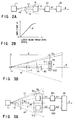
- the received light signal S output from the photo-detector 15 is applied to the amplitude measuring circuit 16 in FIG. 1A, whereas it is applied to an amplitude ratio measuring circuit 21 in FIG. 2A.
- This amplitude ratio measuring circuit 21 is for determining the amplitude ratio Vr between the maximum value Vmax and the minimum value Vmin of the amplitude of the received light signal S.
- the conversion table 22 has stored therein such data that the offset angle ⁇ with respect to the center axis 12 of the photo-detector 15 is output in response to the amplitude ratio Vr, for example, the data representing the relation as indicated by the line segment N in FIG. 2B.
- the ordinate represents the ratio Vr between maximum and minimum values of the amplitude of the received light signal S output from the photo-detector 15, and the abscissa represents the offset angle ⁇ of the photo-detector 15 with respect to the center axis 12.
- the offset detection apparatus which uses the amplitude ratio measuring circuit 21, can determine the correct value of the offset angle ⁇ even when the conversion efficiency of the photo-detector 15 undergoes a change.
- the offset detection apparatus configured as described above thus can determine the offset angle ⁇ of the photo-detector 15 with respect to the center axis 12 without being affected by the change in the conversion efficiency of the photo-detector 15. Also, even when the distance R between the laser beam irradiator 11 and the photo-detector 15 undergoes a change or even when the laser beam 13 changes in level, these changes have no effect on the offset angle ⁇ of the photo-detector 15 with respect to the center axis 12.
- an offset detection apparatus comprising two photo-detectors according to another embodiment of the invention with reference to the circuit configuration diagram of FIG. 3A and the model diagram of FIG. 3B.
- FIG. 3A the component parts identical to the corresponding ones in FIG. 1A are designated by the same reference numerals, respectively, and the description below will be made mainly about the part of the configuration different from FIG. 1A.
- FIG. 3B shows the relation between the arrangement of the laser beam irradiator 11 and the photo-detectors 311, 312 and the irradiated area 14 of the laser beam 13.
- a point P represents a middle point between the photo-detectors 311 and 312 on the platform 32.
- the received light signals S1, S2 output from the photo-detectors 311, 312 constitute amplitude modulated signals having the amplitude changes A1, A2 determined by the offset angles ⁇ 1, ⁇ 2, respectively, with respect to the center axis 12.
- the received light signals S1, S2 are applied to amplitude measuring circuits 331, 332, respectively, thereby to measure amplitude changes A1, A2.
- the amplitude changes A1, A2 are compared in an offset detection circuit 34, thus detecting the direction in which the platform 33 and the photo-detectors 311, 312 are offset, for example, the direction in which the middle point P is offset from the center axis 12.
- the amplitude changes A1, A2 of the received light signals S1, S2 output from the photo-detectors 311, 312, respectively, are equal to each other.
- the photo-detector 311 has a larger displacement from the center axis 12.
- the amplitude change A1 of the received light signal S1 output from the photo-detector 311 becomes larger.
- the amplitude change A2 of the received light signal S2 output from the photo-detector 312 increases relatively. The offset direction is detected by taking advantage of this relation.
- the offset detection circuit 34 judges that "there is no offset", and outputs an offset direction signal D of "0".
- A1 is larger than A2
- the judgement is that "there is an offset”, so that an offset direction signal D of "+1" is output.
- A1 is smaller than A2
- the middle point P is offset toward the position where the photo-detector 242 is arranged.
- the offset detection circuit 34 judges that "there is an offset”, and outputs the offset direction signal D of "-1", for example.
- the above-mentioned method can measure the direction in which the platform 32 or the photo-detectors 311, 312 are offset from the center axis 12.
- the offset amount can be determined by using a conversion table (not shown) showing the relation between the amplitude changes A1, A2 of the received signals S1, S2 and the offset angle ⁇ in terms of functions as described with reference to FIG. 1A.
- the distances between the laser beam irradiator 11 and the photo-detectors 311, 312 are strictly different.
- the change in the irradiation intensity due to this distance difference is negligibly small and poses no practical problem.
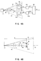
- FIG. 4A shows the component parts identical to the corresponding ones in FIG. 3A and the same reference numerals, respectively, and the description that follows will be made mainly about the configuration different from FIG. 3A.
- FIG. 4B like FIG. 3B, shows the relation between the arrangement of the laser beam irradiator 11 and the photo-detectors 311, 312 and the irradiated area 14 of the laser beam 13.
- the system includes amplitude ratio measuring circuits 411, 412 in place of the amplitude measuring circuits 331, 332 of FIG. 3A.
- the received light signals S1, S2 output from the photo-detectors 311, 312 are applied to the amplitude ratio measuring circuits 411, 412, respectively, thereby to calculate the amplitude ratios Vr1, Vr2 between the maximum value Vmax and the minimum value Vmin of the respective amplitudes.
- the use of the amplitude ratio can determine the correct offset direction even if the conversion efficiencies of the photo-detectors 311, 312 are different from each other. Assuming that the conversion efficiency of the photo-detector 311 is larger by a factor of g than that of the photo-detector 312, for example, the amplitude value of the received light signal of the photo-detector 311 is larger by a factor of g in all, so that the maximum value Vmax and the minimum value Vmin also increase by a factor of g, respectively. The ratio Vr between the two is not affected by the difference in conversion efficiency as seen from the relation of (2).
- the magnitudes of the amplitude ratio Vr1 and the amplitude ratio Vr2 are compared with each other in the offset detection circuit 42.
- the offset detection circuit 42 judges that the offset direction of the platform 32 and the photo-detectors 311, 312, i.e., the position of the middle point P with respect to the center axis 12 is "not offset", and outputs an offset direction signal D of "0", for example.
- Vr1 is larger than Vr2
- the judgement is that "there is an offset toward the photo-detector 311", and an offset direction signal D of "+1" is output, for example.
- Vr1 is smaller than Vr2, in contrast, the offset detection circuit 42 judges that "there is an offset toward the photo-detector 312", and outputs an offset direction signal D of "-1", for example.
- the offset amount is determined using a conversion table (not shown) showing the relation between the ratio between the maximum amplitude and the minimum amplitude of the received light signals S1, S2 in terms of functions.
- the configuration shown in FIG. 4A can determine the offset angles ⁇ 1, ⁇ 2 of the photo-detectors 311, 312 with respect to the center axis 12 without regard to the change in the irradiation intensity due to the fluctuations of the output level of the laser beam irradiator 111 or the change in the distance R from the laser beam irradiator 11.
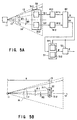
- FIG. 5A shows the component parts identical to the corresponding ones in FIG. 4A, respectively, and the description below will be given mainly of the configuration different from FIG. 4A.
- FIG. 5B shows the relation between the arrangement of the laser beam irradiator 11 and the photo-detectors 311, 312 and the irradiated area 14 of the laser beam 13.
- the two photo-detectors 311, 312 are arranged at a predetermined spatial interval on the platform 32 in such a manner that the straight line connecting them to each other is perpendicular to the center axis 12 at the distance R from the laser beam irradiator 11.
- FIG. 5B shows the relation between the arrangement of the laser beam irradiator 11 and the photo-detectors 311, 312 and the irradiated area 14 of the laser beam 13.
- the point P represents a middle point between the photo-detectors 311, 312 on the platform 32.
- the received light signals S1, S2 output from the photo-detectors 311, 312 are applied to amplitude ratio measuring circuits 411, 412 for determining amplitude ratios Vr1, Vr2, respectively. After that, the amplitude ratios Vr1 and Vr2 are compared in magnitude with each other at the offset detection circuit 42.
- the offset detection circuit 42 judges that the position of the platform 32 and the photo-detectors 311, 312, i.e., the position of the middle point P is "not offset” with respect to the center axis 12, and outputs an offset direction signal D of "0", for example.
- Vr1 is larger than Vr2
- the judgement is that "there is an offset toward the photo-detector 311", and an offset direction signal D of "+1" is produced, for example.
- Vr1 is smaller than Vr2
- the judgement is that "there is an offset toward the photo-detector 312", so that an offset direction signal D of "-1" is output, for example.
- the offset detection circuit 42 selects Vr1 or Vr2, whichever is larger, and outputs the larger one of them as an amplitude ratio signal Vr. Assume that Vr1 is larger than Vr2 and Vr equals Vr1. Then, the amplitude ratio Vr1 is entered in the conversion table 51 as the amplitude ratio signal Vr.
- the conversion table 51 is configured of two conversion tables 511, 512. Since the amplitude ratio Vr1 is applied as an input, the conversion table 511 corresponding to the output of the photo-detector 311 is selected by the offset direction signal D.
- the conversion table 511 has stored therein the relation between the offset angle ⁇ of the photo-detector 311 and the amplitude ratio Vr1, so that the offset angle ⁇ of the photo-detector 311 from the center axis 12 can be determined using the amplitude ratio Vr1.
- the offset direction signal D determined in the amplitude ratio comparator circuit 42 and the offset angle ⁇ determined from the conversion table 51 are applied to an error signal calculation circuit 52, thereby producing an error signal containing the offset signal of the photo-detector 311, i.e., what is called an error signal E containing the data on the offset direction and the offset amount.
- the error signal E is expressed as an offset value with a sign from the offset direction D and the offset angle ⁇ , as follows.
- the sign of equation (3) is undesirably reversed between when the offset amount is small and the two photo-detectors 311, 312 are located on opposite sides of the center axis and when the offset amount is large and both the photo-detectors 311, 312 are on the same side of the center axis 12.
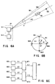
- FIGS. 6A, 6B, 6C a flying object guiding system according to an embodiment of the present invention will be explained with reference to FIGS. 6A, 6B, 6C.
- reference numeral 61 designates a guiding means installed in a launching base or on an airplane carrying the flying object.
- the guiding means includes a laser beam irradiator 611 and a scanning drive unit 612.
- the laser beam irradiator 611 which has a similar configuration to the offset detection apparatus described with reference to FIG. 1B, irradiates the laser beam 62 conically while rotating in the direction of arrow Y about an axis 63, and forms an irradiated area 64 similar to the one described with reference to FIGS. 1C and 1D.
- the scanning drive unit 612 is for controlling the direction of a rotative axis 63 with respect to the laser beam irradiator 6111. For example, the center axis 63 of the irradiated area 64 is controlled toward a target 65, or a flying object 66 proceeding toward the target 65 is controlled to be located within the irradiated area 64.
- the flying object 66 has arranged thereon, as shown by points A to D in FIG. 6B, four photo-detectors 661, 662, 663, 664 equidistantly from each other along a common circumference on the body surface thereof, for example, and contains therein a steering control unit operated based on the offset detection.
- FIG. 6B showing relative positions of the photo-detectors
- FIG. 6C showing a configuration of the steering control unit mounted on the flying object.
- the steering control unit applies the received light signals S1, S3 output from the photo-detector 661 at point A and the photo-detector 663 at point C to an offset detection circuit 671, and processes them in the same manner as described in the embodiments of the offset detection apparatus described above, thus producing the offset direction and the offset amount in the direction of the line segment AC, i.e., an offset signal E1.
- the received light signals S2, S4 of the photo-detector 662 at point B and the photo-detector 664 at point D are applied to the offset detection circuit 672 and an offset signal E2 is output in the direction of the line segment B-D.
- These offset signals E1, E2 are applied to a steering unit 68.
- the steering unit 68 calculates a steering vector N with respect to the center axis 64 based on the offset signals E1, E2.
- the flying object 66 thus is steered to minimize the steering vector N and controlled to proceed along the center axis 64.
- the flying object 66 flies toward a target 65.
- the offset signals E1, E2 both are generated as an error.
- the direction in which the flying object 66 proceeds is corrected to reduce the offset signals E1, E2 to zero. In this way, the flying object 66 can be guided toward the target 65.
- FIG. 7 the component parts identical to the corresponding ones of FIG. 6A are designated by the same reference numerals, respectively, and the description that follows will be limited to the configuration different from FIG. 6A.
- a target setting sensor 71 is installed in the flying object launching base or on the airplane carrying the flying object.
- the position or speed of the target 65 or the like target information TD are detected by the sensor 71.
- the target information TD thus detected is applied to an irradiation direction calculator 72.
- This irradiation direction calculator 72 calculates a future position of the target 65, for example, on the basis of the target information TD and applies the future position data thus calculated to the scanning drive unit 612.
- the scanning drive unit 612 drives the laser beam irradiator 611 in such a manner that the center axis of the irradiated area 64 coincides with the future position of the target 65, for example.
- the center axis 63 is directed always toward the target 65.
- the flying object 66 is guided along the center axis 63 toward the target 65.
- the method of guiding the flying object is similar to the one explained in the embodiment of FIG. 6A and will not be explained any further.
- FIG. 8 the component parts identical to the corresponding ones in FIG. 7 are designated by the same reference numerals, respectively, and the description that follows will be limited to the configuration different from FIG. 7.
- a flying object setting sensor 81 for detecting the positional information FD of the flying object 66 is arranged in the flying object launching base or on the airplane carrying the flying object.
- the sensor 81 detects the positional information FD of the flying object 66, which positional information FD is applied to the irradiation direction calculator 72.
- the irradiation direction calculator 72 calculates the laser beam orientation in such a manner that the center axis 63 of the irradiated area 64 is located at the middle point between the positional information FD and the target 65 of the flying object 66 and that the flying object 66 is included in the irradiated area 64.
- the result of this calculation is transmitted to the scanning drive unit 612 so that the laser beam irradiated from the laser beam irradiator 611 is controlled to proceed in the calculated orientation.
- the flying object 66 is guided gradually toward the center axis 63, so that the flying object 66 and the target 65 enter the same irradiated area.
- the flying object 66 is guided toward the target 66 in the same manner as described with reference to FIG. 7.
- the positional information FD of the flying object 66 is detected and the orientation of the laser beam is controlled in such a manner that the flying object is included in the irradiated area 64.
- the embodiment therefore is effectively applicable to the guiding operation in the case where the flying object 66 is displaced from the irradiated area 64 of the laser beam.
- FIG. 9 the component parts identical to the corresponding ones in FIG. 8 are designated by the same reference numerals, respectively, and the description that follows will be limited to the configuration different from FIG. 8.
- both a target setting sensor 71 for observing the target 65 and a flying object setting sensor 81 for observing the flying object 66 are arranged in a flying object launching base or on an airplane carrying the flying object.
- the positional information TD of the flying object obtained from the flying object setting sensor 81 and the target positional information FD obtained from the target setting sensor 71 are applied to the irradiation direction calculator 72.
- the irradiation direction calculator 72 calculates the direction of the center axis 63 in such a manner that the center axis 63 of the irradiated area 64 is located at the middle point between the position of the flying object 66 and the target 65 and then in such a manner that the flying object 66 is included in the irradiated area 64.
- the result of this calculation is transmitted to the scanning drive unit 612, so that the center axis 63 of the laser beam irradiator 611 is oriented in the calculated direction.
- the flying object 66 located within the irradiated area 64 is controlled toward the center axis 63. After that, the flying object 66 continues to fly in such a manner as to approach the center axis 63 until the target 65 and the flying object 66 enter the same irradiated area. Once the center axis 63 is oriented toward the target 65, the flying object 66 flies toward the target 65 and is guided in the direction toward the target.
- each of the above-mentioned embodiments refers to the case in which the laser beam is a continuous wave.
- the present invention is applicable, however, also to the case in which the laser beam is pulse modulated by providing the photo-detector with a circuit for detecting the average value or the wave crest value of the pulses.
- FIG. 10A shows a configuration of a steering control unit mounted on the flying object.
- Numeral 101 designates a photo-detector.
- the waveform of the received light signal S output from the photo-detector 101 assumes a pulse form as shown in FIG. 10B (outputs S11, S21, S31 and so on).
- the envelope waveform W of the pulse-like output of the received light signal S is equivalent to the one shown in FIG. 1E changing in the period T.
- the crest value H of each pulse-like output S11, S12, S13 and so on is detected, for example, by a pulse wave crest detection circuit 102, and the maximum value Vmax and the minimum value Vmin of the envelope waveform W is calculated from the crest value H are calculated by an amplitude detection circuit 103 thereby to determine an amplitude change A.
- the maximum value Vmax and the minimum value Vmin detected this way, the offset direction and the offset amount can be detected and the guiding operation with a light wave can be performed in the same manner as with the continuous wave.
- the maximum value or the minimum value of the pulse crest can be approximated to Vmax and Vmin, respectively, if the pulse train is sufficiently high in density.
- FIG. 11A shows the case in which photo-detectors 111, 112 are arranged at points A and C, respectively, 180° apart from each other. In this case, only an offset signal E along a single axis indicated by arrow in FIG. 11A is obtained from the two photo-detectors 111, 112. As shown in FIG.
- offset signals E1, E2 in two directions can be produced by providing a time lag between the state in which the photo-detectors 111, 112 are located at points A and C, respectively, and the state in which the photo-detectors 111, 112 are located at points B and D, respectively. It is thus possible to calculate the steering vector N.
- the flying object can thus be guided in the direction toward a target located in a three-dimensional space.
- FIG. 11C shows the case including a single photo-detector.
- the single photo-detector 111 is arranged around the body 110 and rotated by 90° at a time. Then, four observation points A, B, C, D can be realized. Consequently, offset signals in two directions can be produced whereby it is possible to determine the steering vector for guiding the flying object.
- FIG. 11D shows the case in which three photo-detectors are included. Specifically, in FIG. 11D, assume that three photo-detectors 111, 112, 113 are located at points A, B, C, respectively. An offset signal E1 along the direction A-B is produced from the photo-detectors 111, 112 at points A, B, an offset signal E2 along the direction B-C is produced from the photo-detectors 112, 113 at points B, C and an offset signal E3 along the direction C-A is produced from the photo-detectors 113, 111 located points C, A, respectively, as an error signal. The vector calculation as shown in FIG. 11E is performed using these three offset signals E1, E2, E3 thereby to produce a steering vector N.
- the steering vector N can be obtained even when the directions of the offset signals are not perpendicular to each other.
- the target setting sensor and the flying object setting sensor are configured independently of each other.
- the functions of these two sensors can be integrated into a single sensor with equal effect.
- an offset distance can be used as the offset amount in the case where photo-detectors are arranged at points to which the distance is measurable or at predetermined points.
- the magnitude of the received light signal output from the photo-detector is expressed in voltage, other units such as current or power can alternatively be used for expressing the incident energy amount directly or indirectly.
- FIGS. 12A to 12H The component parts identical to the corresponding ones in the above-mentioned embodiments are denoted by the same reference numerals, respectively, and will not be described again.
- FIG. 12A shows the manner in which the conically-scanned laser beam is irradiated.
- the laser beam 212 emitted from the laser beam irradiator 211 has a maximum intensity in the direction at the beam orientation center 213 as shown in FIG. 12B and has such an intensity distribution that the irradiation intensity thereof is monotonically attenuated progressively according as it is offset from the beam orientation center.
- This laser beam 212 is rotated around the rotative axis Z in such a manner that the laser beam always has a predetermined eccentric angle ⁇ from the center axis of the scanning rotation of the laser beam.
- an irradiation space is formed with a conical beam orientation center 213 of the laser beam 212.
- the received light signal S from the photo-detector 216 is a periodical signal S having the same period T as the scanning rotation of the laser beam 212 as shown in FIG. 12C unless the photo-detector 216 is located on the center axis Z of the rotative scanning of the laser beam.
- the photo-detector 216 is for converting the received light energy into a received light signal such as a voltage signal.
- the two photo-detectors 217, 218 are arranged 2d apart from each other on the rear part of the flying object as shown in FIG. 12D, for example, in this embodiment.
- the received light signals from the two photo-detectors 217, 218 are assumed to be S1 and S2, respectively. Also, assume that the middle point between the two sensors 217, 218 is designated as C.
- the two photo-detectors 217, 218 detect a periodical signal conforming with the respective positions.
- phase difference between the signals S1, S2 from the two sensors 217, 218 is ⁇ .
- the phase difference between S1 and S3 represents the time lag from a local maximum value of S1 to a local maximum value of S2 in a standardization with the laser beam rotative period as 2 ⁇ , as shown in FIG. 12E.
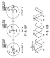
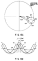
- FIG. 12F is a view from the laser beam irradiator 211 toward the laser beam irradiated space.
- FIG. 12G shows an example of signals from the two corresponding photo-detectors 217, 218, respectively.
- the phase difference ⁇ between S1 and S2 is ⁇ .
- phase difference ⁇ holds the relation ⁇ ⁇ ⁇ ⁇ 2 ⁇ .
- the phase difference ⁇ meets the condition 0 ⁇ ⁇ ⁇ ⁇ .
- the phase difference ⁇ is equal to the angle that the position of each of the sensors 217, 218 forms with the rotative center axis Z.
- the positional relation between the middle point C of the sensors 217, 218, and therefore the laser rotative center axis Z is given by a function.
- the position C is assumed to be (x, 0), and the distance between the sensor and C to be d.
- the middle point C (x, 0) can thus be determined from the phase difference ⁇ .
- the middle point C can be guided onto the center axis Z of the laser scanning rotation.
- FIG. 12H shows a configuration of an offset detection apparatus mounted on the flying object.
- the signals S1, S2 produced from two photo-detectors 217, 218 are applied to a phase difference detector 219 for determining the phase difference ⁇ .
- the data on this phase difference ⁇ is applied to a phase difference conversion table 220.
- the phase difference conversion table 220 has registered therein a function between the phase difference ⁇ and an guide signal ⁇ for correcting the phase difference ⁇ thereby to determine a guide signal ⁇ corresponding to the input phase difference ⁇ .
- This guide signal ⁇ is sent to a steering unit not shown and used for steering the flying object.
- an offset of a flying object moving along a single axis can be detected using two photo-detectors 217, 218 and thus a guide signal can be produced.
- the flying object can be guided over the entire range in the two-dimensional plane by adding one more axis.
- the flying object can be guided over the entire range in the two-dimensional plane by adding one more axis.
- four photo-detectors 221 to 224 are arranged symmetrically with respect to each other about the center point C in the rear part of the flying object as shown in FIG. 13A and that the flying object is located in the laser beam irradiated space. Then, by using the signals S1 to S4 from the photo-detectors 221 to 224, the offset in the two-dimensional direction is obtained and thus the flying object can be guided in such a manner as to correct the particular offset.
- FIG. 13B shows a configuration of a flying object guiding system using the four photo-detectors 221 to 224.
- the signals S1 and S3 among the received light signals S1 to S4 obtained by the photo-detectors 221 to 224 are applied to a phase difference detector 225, and the signals S2, S4 are applied to a phase difference detector 226.
- the phase difference detector 225 detects the phase difference ⁇ 1 between the signals S1 and S2, and the phase difference detector 226 detects the phase difference ⁇ 2 between the signals S2 and S4.
- phase differences ⁇ 1, ⁇ 2 are assumed to represent the time lag between a local maximum value of S1 and a local maximum value of S3 and the time lag between a local maximum value of S2 and a local maximum value of S4, respectively, in a standardization of the laser beam rotative period as 2 ⁇ .
- the phase differences ⁇ 1, ⁇ 2 obtained in the phase difference detectors 225, 226, respectively, are converted into guide signals ⁇ 1, ⁇ 2, respectively, by the phase difference conversion tables 227, 228, and sent to a steering unit not shown for use in guiding the flying object.
- FIG. 13C shows the relation between the points in the space where the photo-detectors 221 to 224 are arranged and the phase differences
- FIG. 13D shows the received light signals S1 to S4 in that state.
- the use of the phase difference conversion tables 227, 228 makes it possible to determine the offset movement of an axis perpendicular to the axis connecting the photo-detectors 221 and 223 from the phase difference ⁇ 1, and the offset movement of an axis perpendicular to the axis connecting the photo-detectors 222 and 224 from the phase difference ⁇ 2.
- guide signals can be obtained from the four received light signals for the movement of the flying object in a two-dimensional plane.
- the use of CW (continuous wave) format is presupposed, and the laser beam is expressed as a continuous signal waveform as shown in FIG. 14D.
- the invention can be easily realized also by a circuit included in the photo-detector of pulse modulation type for detecting the average value or the pulse wave crest value.
- an irradiated space capable of conically scanning the laser beam about the direction of guiding is formed by a guiding means, a periodical signal due to the conical scanning is detected by a plurality of photo-detectors mounted on the flying object, and the steering amount to the center of the irradiated space is calculated.
- the flying object can be guided to a target without carrying any navigation calculator for sharing a coordinate system with the guiding means, and therefore the flying object can be reduced in size and weight.
- the reduced number of devices mounted can make a more slim body of the flying object for a reduced aerodynamic resistance. The result is an increased speed or a reduced fuel consumption.
- an offset detection apparatus for detecting the amount or the direction of offset from a predetermined axis, and a light wave guiding apparatus capable of guiding a flying object in a predetermined direction even in the absence of a coordinate system shared with the guiding means.
Landscapes
- Engineering & Computer Science (AREA)
- General Engineering & Computer Science (AREA)
- Chemical & Material Sciences (AREA)
- Combustion & Propulsion (AREA)
- Physics & Mathematics (AREA)
- Fluid Mechanics (AREA)
- Aviation & Aerospace Engineering (AREA)
- Length Measuring Devices By Optical Means (AREA)
- Aiming, Guidance, Guns With A Light Source, Armor, Camouflage, And Targets (AREA)
Applications Claiming Priority (6)
| Application Number | Priority Date | Filing Date | Title |
|---|---|---|---|
| JP8259101A JPH10104328A (ja) | 1996-09-30 | 1996-09-30 | オフセット検出装置およびこれを用いた光波誘導装置 |
| JP259101/96 | 1996-09-30 | ||
| JP25910196 | 1996-09-30 | ||
| JP24909597 | 1997-09-12 | ||
| JP249095/97 | 1997-09-12 | ||
| JP9249095A JPH1183391A (ja) | 1997-09-12 | 1997-09-12 | オフセット検出装置及びこれを用いた飛翔体誘導システム |
Publications (2)
| Publication Number | Publication Date |
|---|---|
| EP0833123A2 true EP0833123A2 (fr) | 1998-04-01 |
| EP0833123A3 EP0833123A3 (fr) | 2000-05-17 |
Family
ID=26539089
Family Applications (1)
| Application Number | Title | Priority Date | Filing Date |
|---|---|---|---|
| EP97116801A Withdrawn EP0833123A3 (fr) | 1996-09-30 | 1997-09-26 | Dispositif de détection de décalage et système de guidage d'un objet volant utilisant ce dispositif |
Country Status (4)
| Country | Link |
|---|---|
| US (1) | US5878977A (fr) |
| EP (1) | EP0833123A3 (fr) |
| KR (1) | KR100227202B1 (fr) |
| CA (1) | CA2216588C (fr) |
Cited By (3)
| Publication number | Priority date | Publication date | Assignee | Title |
|---|---|---|---|---|
| EP1124141A3 (fr) * | 2000-02-09 | 2003-12-03 | Robert Bosch Gmbh | Procédé de détermination de position dans une pièce |
| US9534868B1 (en) | 2014-06-03 | 2017-01-03 | Lockheed Martin Corporation | Aerodynamic conformal nose cone and scanning mechanism |
| US9568280B1 (en) | 2013-11-25 | 2017-02-14 | Lockheed Martin Corporation | Solid nose cone and related components |
Families Citing this family (15)
| Publication number | Priority date | Publication date | Assignee | Title |
|---|---|---|---|---|
| US6145784A (en) * | 1997-08-27 | 2000-11-14 | Trw Inc. | Shared aperture dichroic active tracker with background subtraction |
| SE509209C2 (sv) * | 1997-11-28 | 1998-12-14 | Spectra Precision Ab | Anordning och förfarande för att bestämma läget för bearbetande del |
| US7219853B2 (en) * | 2004-06-21 | 2007-05-22 | Raytheon Company | Systems and methods for tracking targets with aimpoint offset |
| US7150428B2 (en) * | 2004-09-03 | 2006-12-19 | Her Majesty The Queen In Right Of Canada, As Represented By The Minister Of National Defence | Beam laser atmospheric scattering trajectory guidance |
| US7168174B2 (en) * | 2005-03-14 | 2007-01-30 | Trimble Navigation Limited | Method and apparatus for machine element control |
| US7946209B2 (en) * | 2006-10-04 | 2011-05-24 | Raytheon Company | Launcher for a projectile having a supercapacitor power supply |
| KR101374396B1 (ko) * | 2012-07-20 | 2014-03-19 | 원정제관(주) | 라이터 검사방법 |
| KR101696361B1 (ko) | 2014-09-18 | 2017-01-13 | 김덕수 | 합성수지 피복용 부표의 제조방법 |
| KR20160033445A (ko) | 2014-09-18 | 2016-03-28 | 김덕수 | 합성수지 피복용 부표와 성형을 위한 연신장치 |
| KR101653730B1 (ko) | 2015-10-20 | 2016-09-09 | (주) 태광 | 스치로폼 코팅 접합형 부표용 원통 슬리브를 이용한 코팅장치와 그 방법 |
| KR101600524B1 (ko) | 2015-10-20 | 2016-03-07 | (주) 태광 | 스치로폼 코팅 접합형 부표용 원통 슬리브를 이용한 홈 코팅장치와 그 방법 |
| KR101600525B1 (ko) | 2015-10-20 | 2016-03-07 | (주) 태광 | 스치로폼 부표를 감싸 성형하는 친환경 부표와 그 제조방법 |
| KR101624681B1 (ko) | 2015-10-20 | 2016-06-07 | (주) 태광 | 친환경 부표의 측면 용접장치와 그 방법 |
| KR102699142B1 (ko) * | 2018-11-22 | 2024-08-28 | 현대자동차주식회사 | 차량 및 그 트레일러 결합 방법 |
| KR102162387B1 (ko) * | 2019-11-15 | 2020-10-06 | 국방과학연구소 | 반능동 레이저 탐지 장치의 추적각 오차를 보정하는 시스템 및 방법 |
Family Cites Families (11)
| Publication number | Priority date | Publication date | Assignee | Title |
|---|---|---|---|---|
| US3964053A (en) * | 1957-03-15 | 1976-06-15 | International Telephone And Telegraph Corporation | Aircraft guiding system |
| US3513315A (en) * | 1966-11-14 | 1970-05-19 | Bofors Ab | System for determining the displacement of an object from a line of sight |
| US3746280A (en) * | 1972-01-28 | 1973-07-17 | Northrop Corp | Vehicle guidance system utilizing conical scan control beam |
| US4014482A (en) * | 1975-04-18 | 1977-03-29 | Mcdonnell Douglas Corporation | Missile director |
| US4020339A (en) * | 1975-05-19 | 1977-04-26 | Aktiebolaget Bofars | System for determining the deviation of an object from a sight line |
| FR2474682A1 (fr) * | 1980-01-29 | 1981-07-31 | Telecommunications Sa | Systeme de guidage d'engin au moyen d'un faisceau lumineux module |
| US4696441A (en) * | 1986-05-06 | 1987-09-29 | The United States Of America As Represented By The Secretary Of The Army | Missile referenced beamrider |
| US4732349A (en) * | 1986-10-08 | 1988-03-22 | Hughes Aircraft Company | Beamrider guidance system |
| JP2638345B2 (ja) * | 1991-08-09 | 1997-08-06 | 日産自動車株式会社 | 飛しょう体の誘導制御方法 |
| JP3327711B2 (ja) * | 1994-12-28 | 2002-09-24 | 株式会社アイ・エイチ・アイ・エアロスペース | レーザ散乱光を用いた飛翔体の誘導制御におけるレーザ散乱光入射方向検出装置 |
| US5685504A (en) * | 1995-06-07 | 1997-11-11 | Hughes Missile Systems Company | Guided projectile system |
-
1997
- 1997-09-25 KR KR1019970048639A patent/KR100227202B1/ko not_active Expired - Fee Related
- 1997-09-26 EP EP97116801A patent/EP0833123A3/fr not_active Withdrawn
- 1997-09-29 CA CA002216588A patent/CA2216588C/fr not_active Expired - Fee Related
- 1997-09-29 US US08/939,505 patent/US5878977A/en not_active Expired - Lifetime
Cited By (3)
| Publication number | Priority date | Publication date | Assignee | Title |
|---|---|---|---|---|
| EP1124141A3 (fr) * | 2000-02-09 | 2003-12-03 | Robert Bosch Gmbh | Procédé de détermination de position dans une pièce |
| US9568280B1 (en) | 2013-11-25 | 2017-02-14 | Lockheed Martin Corporation | Solid nose cone and related components |
| US9534868B1 (en) | 2014-06-03 | 2017-01-03 | Lockheed Martin Corporation | Aerodynamic conformal nose cone and scanning mechanism |
Also Published As
| Publication number | Publication date |
|---|---|
| CA2216588A1 (fr) | 1998-03-30 |
| EP0833123A3 (fr) | 2000-05-17 |
| CA2216588C (fr) | 2004-02-17 |
| US5878977A (en) | 1999-03-09 |
| KR19980024939A (ko) | 1998-07-06 |
| KR100227202B1 (ko) | 1999-10-15 |
Similar Documents
| Publication | Publication Date | Title |
|---|---|---|
| US5878977A (en) | Offset detection apparatus and flying object guiding system using the apparatus | |
| KR100310841B1 (ko) | 이동표적을추적하고그이동표적에고에너지레이저빔을고착하기위한시스템 | |
| US4195799A (en) | System for guiding flying vehicles with light beam | |
| US5742394A (en) | Optical 6D measurement system with two fan shaped beams rotating around one axis | |
| AU618402B2 (en) | Surveillance sensor | |
| US4926050A (en) | Scanning laser based system and method for measurement of distance to a target | |
| US5088659A (en) | Projectile equipped with an infrared search system at its bow | |
| US5128794A (en) | Scanning laser helmet mounted sight | |
| US5780838A (en) | Laser crossbody tracking system and method | |
| US20070103699A1 (en) | Multiple fanned laser beam metrology system | |
| JPH0587823A (ja) | 風向を検出する装置および方法 | |
| KR19990023898A (ko) | 표적 추적용 레이저 지시기 | |
| WO1987002797A1 (fr) | SYSTEME OPTO-ELECTRONIQUE INTELLIGENT D'ARRIMAGE PAR NAVIGATION A l'ESTIME | |
| EP0795115A2 (fr) | Systeme et procede de mesure de positions angulaires | |
| WO1996018080A1 (fr) | Systeme et procede de mesure de positions angulaires | |
| US4696441A (en) | Missile referenced beamrider | |
| JP2010256179A (ja) | 測距方法及び車載測距装置 | |
| US7175130B2 (en) | Missile steering using laser scattering by atmosphere | |
| US5740986A (en) | Method of determining the position of roll of a rolling flying object | |
| US7150428B2 (en) | Beam laser atmospheric scattering trajectory guidance | |
| JPH1183391A (ja) | オフセット検出装置及びこれを用いた飛翔体誘導システム | |
| JPH11248399A (ja) | 飛翔体誘導システム | |
| JPH0480405B2 (fr) | ||
| JPH10104328A (ja) | オフセット検出装置およびこれを用いた光波誘導装置 | |
| JPS61200100A (ja) | 姿勢制御用レ−ザレ−ダ |
Legal Events
| Date | Code | Title | Description |
|---|---|---|---|
| PUAI | Public reference made under article 153(3) epc to a published international application that has entered the european phase |
Free format text: ORIGINAL CODE: 0009012 |
|
| 17P | Request for examination filed |
Effective date: 19971023 |
|
| AK | Designated contracting states |
Kind code of ref document: A2 Designated state(s): DE FR GB IT NL |
|
| PUAL | Search report despatched |
Free format text: ORIGINAL CODE: 0009013 |
|
| AK | Designated contracting states |
Kind code of ref document: A3 Designated state(s): AT BE CH DE DK ES FI FR GB GR IE IT LI LU MC NL PT SE |
|
| AKX | Designation fees paid |
Free format text: DE FR GB IT NL |
|
| 17Q | First examination report despatched |
Effective date: 20030128 |
|
| STAA | Information on the status of an ep patent application or granted ep patent |
Free format text: STATUS: THE APPLICATION IS DEEMED TO BE WITHDRAWN |
|
| 18D | Application deemed to be withdrawn |
Effective date: 20030611 |