EP0833138B1 - Vorrichtung zur Feststellung des Types einer Ausrüstung in Rotation, Überwachungssystem und Parameterregulierung einer assozierten Zentrifuge - Google Patents
Vorrichtung zur Feststellung des Types einer Ausrüstung in Rotation, Überwachungssystem und Parameterregulierung einer assozierten Zentrifuge Download PDFInfo
- Publication number
- EP0833138B1 EP0833138B1 EP97402138A EP97402138A EP0833138B1 EP 0833138 B1 EP0833138 B1 EP 0833138B1 EP 97402138 A EP97402138 A EP 97402138A EP 97402138 A EP97402138 A EP 97402138A EP 0833138 B1 EP0833138 B1 EP 0833138B1
- Authority
- EP
- European Patent Office
- Prior art keywords
- motor
- speed
- type
- centrifuge
- rotation
- Prior art date
- Legal status (The legal status is an assumption and is not a legal conclusion. Google has not performed a legal analysis and makes no representation as to the accuracy of the status listed.)
- Expired - Lifetime
Links
- 230000033228 biological regulation Effects 0.000 title description 9
- 230000001105 regulatory effect Effects 0.000 claims description 6
- 238000012544 monitoring process Methods 0.000 claims description 5
- 230000005291 magnetic effect Effects 0.000 claims description 4
- 230000001276 controlling effect Effects 0.000 claims description 3
- 230000001419 dependent effect Effects 0.000 claims description 3
- 238000004364 calculation method Methods 0.000 description 5
- 238000005259 measurement Methods 0.000 description 3
- 230000006978 adaptation Effects 0.000 description 2
- 230000008901 benefit Effects 0.000 description 2
- 230000006870 function Effects 0.000 description 2
- 230000005355 Hall effect Effects 0.000 description 1
- 230000006399 behavior Effects 0.000 description 1
- 238000005119 centrifugation Methods 0.000 description 1
- 238000010276 construction Methods 0.000 description 1
- 230000006698 induction Effects 0.000 description 1
- 238000000034 method Methods 0.000 description 1
- 238000005057 refrigeration Methods 0.000 description 1
- 238000010792 warming Methods 0.000 description 1
Images
Classifications
-
- B—PERFORMING OPERATIONS; TRANSPORTING
- B04—CENTRIFUGAL APPARATUS OR MACHINES FOR CARRYING-OUT PHYSICAL OR CHEMICAL PROCESSES
- B04B—CENTRIFUGES
- B04B15/00—Other accessories for centrifuges
- B04B15/02—Other accessories for centrifuges for cooling, heating, or heat insulating
-
- B—PERFORMING OPERATIONS; TRANSPORTING
- B04—CENTRIFUGAL APPARATUS OR MACHINES FOR CARRYING-OUT PHYSICAL OR CHEMICAL PROCESSES
- B04B—CENTRIFUGES
- B04B9/00—Drives specially designed for centrifuges; Arrangement or disposition of transmission gearing; Suspending or balancing rotary bowls
- B04B9/10—Control of the drive; Speed regulating
-
- G—PHYSICS
- G01—MEASURING; TESTING
- G01L—MEASURING FORCE, STRESS, TORQUE, WORK, MECHANICAL POWER, MECHANICAL EFFICIENCY, OR FLUID PRESSURE
- G01L3/00—Measuring torque, work, mechanical power, or mechanical efficiency, in general
-
- H—ELECTRICITY
- H02—GENERATION; CONVERSION OR DISTRIBUTION OF ELECTRIC POWER
- H02P—CONTROL OR REGULATION OF ELECTRIC MOTORS, ELECTRIC GENERATORS OR DYNAMO-ELECTRIC CONVERTERS; CONTROLLING TRANSFORMERS, REACTORS OR CHOKE COILS
- H02P23/00—Arrangements or methods for the control of AC motors characterised by a control method other than vector control
- H02P23/08—Controlling based on slip frequency, e.g. adding slip frequency and speed proportional frequency
Definitions
- the present invention relates to a device determining the type of equipment according to the preamble of claim 1.
- the invention is particularly applicable to the identification of the type equipment fitted to a centrifuge.
- the determination of the type of equipment driven in rotation is based on the calculation of the moment of inertia of the equipment and thus requires the use specific sensors and a calculation unit complex.
- JP-A-58 003 591 and JP-A-55 087 018 describe devices for determining the torque supplied by motors induction from their sliding.
- US-4,461.957 describes an electric generator whose operation is controlled using the calculation of a slip value.
- the object of the invention is to provide a device according to the preamble of claim 1, who is from simple structure and does not require planning specific sensors and complex computing unit.
- Another object of the invention is to provide a system for controlling or regulating parameters of operation of a centrifuge from knowledge the type of equipment driven by the engine.
- the invention also relates to a system for monitoring the operation of a centrifuge according to claim 5.
- Claim 6 relates to a particular embodiment of this system.
- the invention also relates to a system for control of operating parameters of a centrifuge according to claim 7.
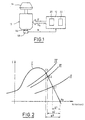
- a motor 10 is shown controlled by a control unit 12 delivering to the motor 10 an AC supply voltage U.
- the motor 10 is an asynchronous electric motor three-phase rotating equipment mounted 14 on the motor shaft 16.
- the speed of rotation of the magnetic field created by the supply voltage U also known as the synchronization speed N s of the motor 10
- control unit 12 ensures the adjustment of the speed of rotation of the motor 10 by means of the adjustment of the frequency f of the supply voltage U.
- the synchronization speed N s of the motor is equal to 50 revolutions per second, or 3000 revolutions per minute.
- the equipment 14 rotates at a speed of rotation N lower than the synchronism speed N s of the rotating magnetic field.
- slip g being represented, for a given synchronism speed N s , by the difference between the synchronism speed N s and the speed of rotation of the motor N, it varies as a function of the speed of rotation N of the motor.
- slip value g varies according to the supply voltage U delivered by the control unit 12, construction characteristics of the engine and of the resistant couple.
- slip g is proportional to the value of the resistive torque of the equipment 14.
- FIG. 2 shows the motor torque (curve I), as well as the resistive torque of the equipment 14 for a given synchronism speed N s of the motor, for different types of equipment (curves II, III and IV) .
- Motor 10 can be fitted with equipment 14 chosen from a set of equipment each having a resistive torque value C, it is thus possible, from the knowledge of the slip g of the motor 10 for particular equipment 14 to know the torque resistant C of this equipment and therefore the type to which it belongs.
- the device shown in the shown in figure 1 comprises a member 18 for measuring the speed of rotation of the equipment 14 fixed on the shaft 16 of the motor and delivering to the control unit 12 the actual value of the rotational speed N of the motor 10.
- the measurement member 18 is made up of all types of sensors suitable for the intended use, for example a tachometer, a device for measuring magnetic or hall effect speed, or a notched disc associated with a light source and a photoelectric receiver delivering to the control unit 12 electrical pulses whose frequency varies in depending on the rotation speed N of the motor, or by any other type of measurement means.
- control unit 12 comprises a computer 20 ensuring the calculation, according to the relation (1) mentioned above, of the synchronism speed N s of the motor, as well as the calculation of the value of a characteristic representative of the slip g.
- This characteristic characteristic of engine slip is calculated from the comparison of the calculated value of the synchronism speed N s and of the actual speed of rotation N of the engine 10 delivered by the measuring member 18.
- control unit 12 includes a memory 22 in which a set of slip values each corresponding to a value of resistant torque and previously obtained so experimental by equipping a three-phase asynchronous motor same type as motor 10 with different types of the equipment 14 each having a predefined value of resisting torque and determining the slip g engine correspondent for each piece of equipment.
- the control unit 12 then performs, using of a comparator deposited in the computer 20, the comparison between the value of the representative characteristic of the calculated slip g and the values of slip stored in memory 22, allowing thus determining the value of the resisting torque rotor 14 and therefore the type of rotor mounted on tree 16.
- control unit 12 compares the value of the resistive torque identified with a set of stored resistive torque values in the control unit 12.
- this resistant torque identification device can be used for determining the type of equipment equipping a centrifuge to ensure unwinding a safe centrifugation cycle as well as adaptation of operating regulation parameters of the centrifuge.
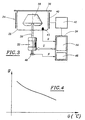
- FIG 3 there is shown schematically a centrifuge equipped with such a device.
- the centrifuge designated by the general reference numeral 24, comprises a chamber 26 in which is placed a mounted rotor 28 on the shaft 30 of an asynchronous electric motor 32 controlled by a control unit 34 of its supply.
- the rotor 28 comprises in known manner means receiving tubes containing samples to centrifuge, not shown.
- a cover 36 is fixed from removably on the chamber 26, to allow the loading and unloading of the rotor 28.
- room 26 has means refrigeration 40, of conventional type, suitable for cool chamber 26 under the control of the command 34, via a regulator 42 of classic type, proportional coefficient, proportional-integral or integral.
- the chamber 26 is further provided with a sensor 43 of the temperature ⁇ of the air present in it connected to control unit 34.
- the control unit 34 is equipped with a device for identifying the resistive torque of the rotor 28 comprising a computer 44 and a memory 46 and allowing, as previously mentioned to identify the couple resistance of the rotor mounted on the shaft 30, by comparison of the value representative of the slip calculated by the control unit 34 with a set of values of slip memorized in memory 46 and obtained previously experimentally for values of corresponding resistant torque.
- a device for identifying the resistive torque of the rotor 28 comprising a computer 44 and a memory 46 and allowing, as previously mentioned to identify the couple resistance of the rotor mounted on the shaft 30, by comparison of the value representative of the slip calculated by the control unit 34 with a set of values of slip memorized in memory 46 and obtained previously experimentally for values of corresponding resistant torque.
- the resistant torque thus identified allows when determining the type of rotor to which belongs the rotor mounted on the shaft 30.
- the value of the slip g of the rotor being, in known manner, a quantity dependent on the air temperature in the vicinity of the rotor, the value of the temperature delivered by the sensor 43 makes it possible to increase the accuracy of determining the resistive torque rotor.
- the stored slip values in memory 46 are, according to one embodiment particular, values that vary depending on the temperature ⁇ of chamber 26, according to the curve shown in figure 4.
- centrifuge is capable, from the measurement of the engine speed 32 delivered to the control unit 34 by a sensor 48 specific, to monitor the type of rotor mounted on the shaft 30.
- control unit 34 can detect the incompatibility between the rotor 28 and the speed programmed by the operator and emits in this case an alarm, using known technique, identifying thus to the operator the detected incompatibility.
- control unit 34 adjusts the frequency f from the supply voltage U of the motor 32 to the maximum value of the permissible speed for the rotor 28 and the centrifuge.
- the temperature of chamber 26 is regulated under the control of the control unit 34, in order to keep constant the temperature in room 26 whatever the friction generated by the rotation of the rotor 28 and which tend to increase the temperature inside the room 26.
- the temperature sensor 43 delivers control values 34 to the control unit 34 the temperature of chamber 26 in order to carry out a regulation of this temperature, by regulation known in themselves.
- each type of rotor has a specific thermal behavior, so it's necessary to adapt the temperature regulation to the type of rotor mounted on the shaft 30.
- the central control unit 34 has in its memory 46, associated with the values of resistant torque each corresponding to a type of rotor, a set of predetermined parameter values temperature control each corresponding to a rotor type and intended for regulator 42. As before, these temperature control parameters are previously obtained using experimental results further allowing to determine for each type of rotor capable of being mounted on the shaft 30, the warming generated for different values of rotation speed.
- control unit 34 can then, at from the identification of the rotor, determine the optimum centrifuge regulation parameters and provide the regulator 42 with the values of these parameters for adjusting the temperature of chamber 26.
- cruise control can benefit of the same system of adaptation of its regulation parameters once the rotor 28 has been identified by the control unit 34.
- the centrifuge equipped with a such a system allows, on the one hand, to recognize the type of rotor fitted to the motor to prevent it from rotates at a higher speed than it or that the centrifuge is capable of supporting and, on the other hand, to adjust the operating regulation parameters of the centrifuge depending on the type of rotor and the motor rotation speed.
Landscapes
- Physics & Mathematics (AREA)
- General Physics & Mathematics (AREA)
- Engineering & Computer Science (AREA)
- Power Engineering (AREA)
- Centrifugal Separators (AREA)
- Control Of Ac Motors In General (AREA)
- Control Of Direct Current Motors (AREA)
Claims (7)
- Vorrichtung zur Bestimmung des Typs einer in Drehung versetzten Einrichtung (14; 28), die einem Asynchron-Elektromotor (10; 32) zugeordnet ist, der durch eine Steuereinheit (12; 34) gesteuert wird, die dem Motor (10; 32) eine Wechselspannung (U) zur Versorgung und zur Steuerung der Drehgeschwindigkeit des Motors (10; 32) liefert, dadurch gekennzeichnet, daß sie folgendes aufweist: Mittel (18; 48) zum Messen der Drehgeschwindigkeit des Motors (10; 32), Mittel (20; 44) zum Berechnen eines für den Schlupf des Motors repräsentativen Merkmals und diesen Rechenmitteln (20; 44) zugeordnete Mittel zum Vergleichen des errechneten Werts dieses Merkmals und einer Anzahl von zuvor bestimmten Schlupfwerten, wobei diese zuvor bestimmten Werte in einem den Vergleichsmitteln zugeordneten Speicher (22; 46) gespeichert sind und jeweils einem Wert eines Widerstandsmoments entsprechen, zum Zweck der Identifizierung des Widerstandsmoments dieser Einrichtung (14; 28), und Mittel zum Vergleichen des identifizierten Werts des Widerstandsmoments mit einer Anzahl von Widerstandsmomentswerten, die in einem den Vergleichsmitteln zugeordneten Speicher gespeichert sind, zum Zweck der Bestimmung des Typs der in Drehung versetzten Einrichtung.
- Vorrichtung nach Anspruch 1, dadurch gekennzeichnet, daß die Mittel (20; 44) zur Berechnung des für den Schlupf des Motors (10; 32) repräsentativen Merkmals Mittel zum Vergleichen der Synchrongeschwindigkeit des durch die Versorgungsspannung erzeugten Magnetfelds und der gemessenen Drehgeschwindigkeit des Motors (10; 32) aufweisen.
- Vorrichtung nach einem der Ansprüche 1 und 2, dadurch gekennzeichnet, daß dieses für den Schlupf repräsentative Merkmal ein von der Temperatur abhängiges Merkmal ist und daß sie zur Erhöhung der Genauigkeit der Identifizierung des Widerstandsmoments außerdem Mittel zum Messen der Temperatur der Luft in Nähe der Einrichtung umfaßt.
- Vorrichtung nach einem der Ansprüche 1 bis 3, dadurch gekennzeichnet, daß die in Drehung versetzte Einrichtung aus dem Rotor (28) einer Zentrifuge (24) besteht.
- System zur Überwachung des Betriebs einer Zentrifuge, umfassend einen Asynchron-Elektromotor (10; 32), der durch eine Steuereinheit (12; 34) gesteuert wird, die dem Motor eine Wechselspannung (U) zur Versorgung und zur Steuerung der Drehgeschwindigkeit des Motors (10; 32) liefert, dadurch gekennzeichnet, daß die Steuereinheit (12; 34) eine Vorrichtung zur Bestimmung des Typs der in Drehung versetzten Einrichtung nach einem der Ansprüche 1 bis 4 umfasst, wobei die in der Steuereinheit gespeicherten Widerstandsmomentwerte jeweils dem Widerstandmoment einer Einrichtung entsprechen, die der Motor mit einer bestimmten Drehgeschwindigkeit antreiben darf, zum Zweck der Überwachung der Kompatibilität zwischen der in Drehung versetzten Einrichtung (14; 28) und der Zentrifuge (10; 32).
- Überwachungssystem nach Anspruch 5, dadurch gekennzeichnet, daß die Steuereinheit (12; 34) Mittel zur Begrenzung der Drehgeschwindigkeit der Einrichtung aufweist, die dafür ausgelegt sind, die Drehgeschwindigkeit dieser Einrichtung auf einen zugelassenen Höchstwert der Drehgeschwindigkeit der Einrichtung (14; 28) zu begrenzen.
- System zur Steuerung der Betriebsparameter einer Zentrifuge (24), umfassend einen Asynchron-Elektromotor (32), der durch eine Steuereinheit (34) gesteuert wird, die dem Motor (32) eine Spannung (U) zur Versorgung und zur Steuerung der Drehgeschwindigkeit des Motors (32) liefert, und der einen in einer Kammer (26) angeordneten Rotor (28) in Drehung versetzt, und Mittel (34; 46) zur Regulierung von Betriebsparametern der Zentrifuge (24), dadurch gekennzeichnet, daß es eine Vorrichtung zur Bestimmung des Typs der in Drehung versetzten Einrichtung nach Anspruch 4 aufweist, daß die Steuereinheit den Speicher (46) zur Speicherung der Widerstandsmomentwerte umfaßt, daß die gespeicherten Widerstandsmomentwerte, die jeweils einem Rotortyp (28) entsprechen, jeweils einer Anzahl von diesem Typ von Rotor (28) entsprechenden Parametern zur Regulierung des Betriebs der Zentrifuge (34) zugeordnet sind, und daß die Bestimmungsvorrichtung dafür ausgelegt ist, den Regulierungsmitteln die Werte der Regulierungsparameter zu liefern, die dem bestimmten Typ des Rotors (28) entsprechen.
Applications Claiming Priority (2)
| Application Number | Priority Date | Filing Date | Title |
|---|---|---|---|
| FR9611822A FR2754055B1 (fr) | 1996-09-27 | 1996-09-27 | Dispositif de determination du couple resistant d'un equipement en rotation, systeme de surveillance d'un moteur electrique et systeme de regulation de parametres d'un centrifugeur associe |
| FR9611822 | 1996-09-27 |
Publications (2)
| Publication Number | Publication Date |
|---|---|
| EP0833138A1 EP0833138A1 (de) | 1998-04-01 |
| EP0833138B1 true EP0833138B1 (de) | 2003-03-19 |
Family
ID=9496138
Family Applications (1)
| Application Number | Title | Priority Date | Filing Date |
|---|---|---|---|
| EP97402138A Expired - Lifetime EP0833138B1 (de) | 1996-09-27 | 1997-09-15 | Vorrichtung zur Feststellung des Types einer Ausrüstung in Rotation, Überwachungssystem und Parameterregulierung einer assozierten Zentrifuge |
Country Status (7)
| Country | Link |
|---|---|
| US (1) | US6205405B1 (de) |
| EP (1) | EP0833138B1 (de) |
| JP (1) | JPH114589A (de) |
| AT (1) | ATE235047T1 (de) |
| DE (1) | DE69719894T2 (de) |
| ES (1) | ES2195098T3 (de) |
| FR (1) | FR2754055B1 (de) |
Families Citing this family (25)
| Publication number | Priority date | Publication date | Assignee | Title |
|---|---|---|---|---|
| US6617705B1 (en) * | 1998-10-28 | 2003-09-09 | Ocean Power Technologies, Inc. | Protection arrangement for natural energy power generation systems |
| US6388740B1 (en) * | 1999-06-22 | 2002-05-14 | Robert A. Levine | Method and apparatus for timing intermittent illumination of a sample tube positioned on a centrifuge platen and for calibrating a sample tube imaging system |
| DE19932721C1 (de) * | 1999-07-16 | 2001-01-18 | Eppendorf Geraetebau Netheler | Laborzentrifuge mit Kühlaggregat |
| US6368265B1 (en) * | 2000-04-11 | 2002-04-09 | Kendro Laboratory Products, L.P. | Method and system for energy management and overspeed protection of a centrifuge |
| US6350224B1 (en) * | 2000-07-17 | 2002-02-26 | Westinghouse Savannah River Company, Llc | Centrifugal unbalance detection system |
| US6731019B2 (en) * | 2000-08-07 | 2004-05-04 | Ocean Power Technologies, Inc. | Apparatus and method for optimizing the power transfer produced by a wave energy converter (WEC) |
| US6765307B2 (en) * | 2001-01-16 | 2004-07-20 | Olean Power Technologies, Inc. | Wave energy converter (WEC) |
| US7458928B2 (en) * | 2002-06-13 | 2008-12-02 | Kendro Laboratory Products, Lp | Centrifuge energy management system and method |
| DK175744B1 (da) * | 2002-12-12 | 2005-02-07 | Exhausto As | Sikkerhedskredslöb til rögrörsventilator |
| US6943509B2 (en) * | 2003-07-09 | 2005-09-13 | Kendro Laboratory Products, Lp | Rotor speed control device and method |
| US6903525B2 (en) * | 2003-08-05 | 2005-06-07 | Kendro Laboratory Products, Lp | Motor temperature sensor system and method to determine motor performance |
| US6986727B2 (en) * | 2003-12-23 | 2006-01-17 | Caterpillar Inc. | Retarding control for an electric drive machine |
| US20070284170A1 (en) * | 2006-06-13 | 2007-12-13 | Kuras Brian D | Retarding control for hydromechanical drive machine |
| DE102006058955B4 (de) * | 2006-12-12 | 2014-07-24 | DüRR DENTAL AG | Saugvorrichtung für dentale, medizinische und industrielle Zwecke |
| US8051709B2 (en) * | 2009-02-25 | 2011-11-08 | General Electric Company | Method and apparatus for pre-spinning rotor forgings |
| CN102162759B (zh) * | 2010-12-29 | 2014-07-30 | 奇瑞汽车股份有限公司 | 一种电动汽车扭矩测试方法和测试系统 |
| JP5948971B2 (ja) * | 2011-04-15 | 2016-07-06 | 日立工機株式会社 | 遠心分離機 |
| CN102829910B (zh) * | 2011-06-13 | 2014-12-10 | 上海电驱动股份有限公司 | 一种宽电压节能型永磁电机测功系统 |
| CN102937674A (zh) * | 2011-08-16 | 2013-02-20 | 大庆恒通电子有限公司 | 一种用于抽油机工作效率及平衡度分析的装置及方法 |
| CN102513224B (zh) * | 2011-10-26 | 2014-01-08 | 中国石油集团西部钻探工程有限公司 | 岩心离心机液体监测装置 |
| CN102829908A (zh) * | 2012-08-27 | 2012-12-19 | 哈尔滨工业大学 | 三轴气浮台综合干扰力矩测量方法 |
| CN104034462A (zh) * | 2014-06-03 | 2014-09-10 | 杭州电子科技大学 | 一种数字非接触式扭矩测量方法 |
| CN104034465B (zh) * | 2014-07-01 | 2016-04-13 | 中国船舶重工集团公司第七○二研究所 | 调距桨单片桨叶转叶力矩测量装置中的测力机构 |
| CN116570789B (zh) * | 2023-07-13 | 2023-10-13 | 四川天府南格尔生物医学有限公司 | 一种血浆采集系统及采集方法 |
| CN117232708B (zh) * | 2023-11-10 | 2024-03-15 | 成都飞机工业(集团)有限责任公司 | 一种检查评估航空发动机转子轴承摩擦力矩的方法 |
Citations (2)
| Publication number | Priority date | Publication date | Assignee | Title |
|---|---|---|---|---|
| JPS5587018A (en) * | 1978-12-25 | 1980-07-01 | Shin Nippon Koki Kk | Arithmetic unit for motor torque of induction motor |
| JPS583591A (ja) * | 1981-06-25 | 1983-01-10 | Toyo Electric Mfg Co Ltd | 誘導電動機制御方法 |
Family Cites Families (16)
| Publication number | Priority date | Publication date | Assignee | Title |
|---|---|---|---|---|
| SE433777B (sv) * | 1980-03-26 | 1984-06-12 | Elfi Innovationer | Sett och anordning att for overvakning detektera en asynkronmotors lindningstemperatur |
| JPS583592A (ja) * | 1981-06-24 | 1983-01-10 | Mitsubishi Electric Corp | 電動機の制御装置 |
| JPS6022598B2 (ja) * | 1981-06-24 | 1985-06-03 | 三菱電機株式会社 | 電動機の回転制御装置 |
| US4461957A (en) * | 1982-06-17 | 1984-07-24 | Control Data Corporation | Speed tolerant alternator system for wind or hydraulic power generation |
| DE3334725A1 (de) * | 1983-09-26 | 1985-04-11 | Wabco Westinghouse Fahrzeugbremsen GmbH, 3000 Hannover | Einrichtung zum schutz einer kupplung gegen ueberhitzung |
| JPS6348180A (ja) * | 1986-04-11 | 1988-02-29 | Nippon Electric Ind Co Ltd | 辷り速度を用いた加減速制御装置 |
| JPS6388416A (ja) * | 1986-10-01 | 1988-04-19 | Matsushita Electric Ind Co Ltd | モ−タ特性試験方法 |
| US4822331A (en) * | 1987-11-09 | 1989-04-18 | Taylor David C | Centrifuge |
| US5255192A (en) * | 1990-05-18 | 1993-10-19 | Mitsubishi Jidosha Kogyo Kabushiki Kaisha | Output control apparatus for vehicle |
| JPH0512155A (ja) * | 1991-07-04 | 1993-01-22 | Toshiba Corp | 誘導電動機の制御装置 |
| SE500804C2 (sv) * | 1992-02-20 | 1994-09-05 | Wlodzimierz Cwejman | Anordning för styrning av elektriska motorer |
| DE69404927T2 (de) * | 1993-09-27 | 1998-03-19 | Matsushita Electric Works Ltd | Verfahren und Anordnung für Vektorsteuerung zum Steuern der Rotorgeschwindigkeit eines Induktionsmotor |
| JP3101789B2 (ja) * | 1993-12-13 | 2000-10-23 | 株式会社ユニシアジェックス | ロックアップ機構の故障診断装置 |
| JP3384134B2 (ja) * | 1994-08-17 | 2003-03-10 | 日立工機株式会社 | 遠心機に於るロータの過回転防止制御装置 |
| US5680025A (en) * | 1994-10-07 | 1997-10-21 | Csi Technology, Inc. | Proactive motor monitoring for avoiding premature failures and for fault recognition |
| JP3565938B2 (ja) * | 1995-03-14 | 2004-09-15 | トヨタ自動車株式会社 | 車両の制動力制御装置 |
-
1996
- 1996-09-27 FR FR9611822A patent/FR2754055B1/fr not_active Expired - Fee Related
-
1997
- 1997-09-15 DE DE69719894T patent/DE69719894T2/de not_active Expired - Lifetime
- 1997-09-15 AT AT97402138T patent/ATE235047T1/de not_active IP Right Cessation
- 1997-09-15 EP EP97402138A patent/EP0833138B1/de not_active Expired - Lifetime
- 1997-09-15 ES ES97402138T patent/ES2195098T3/es not_active Expired - Lifetime
- 1997-09-26 US US08/939,006 patent/US6205405B1/en not_active Expired - Fee Related
- 1997-09-29 JP JP9281416A patent/JPH114589A/ja active Pending
Patent Citations (2)
| Publication number | Priority date | Publication date | Assignee | Title |
|---|---|---|---|---|
| JPS5587018A (en) * | 1978-12-25 | 1980-07-01 | Shin Nippon Koki Kk | Arithmetic unit for motor torque of induction motor |
| JPS583591A (ja) * | 1981-06-25 | 1983-01-10 | Toyo Electric Mfg Co Ltd | 誘導電動機制御方法 |
Also Published As
| Publication number | Publication date |
|---|---|
| DE69719894D1 (de) | 2003-04-24 |
| ES2195098T3 (es) | 2003-12-01 |
| DE69719894T2 (de) | 2003-11-13 |
| ATE235047T1 (de) | 2003-04-15 |
| FR2754055B1 (fr) | 1998-12-18 |
| FR2754055A1 (fr) | 1998-04-03 |
| JPH114589A (ja) | 1999-01-06 |
| EP0833138A1 (de) | 1998-04-01 |
| US6205405B1 (en) | 2001-03-20 |
Similar Documents
| Publication | Publication Date | Title |
|---|---|---|
| EP0833138B1 (de) | Vorrichtung zur Feststellung des Types einer Ausrüstung in Rotation, Überwachungssystem und Parameterregulierung einer assozierten Zentrifuge | |
| EP0802606B1 (de) | Verfahren zur Steuerung des Erregungstroms eines Fahrzeuggenerators mit digitaler Verarbeitung und Steuerungsvorrichtung zur Durchführung dieses Verfahrens | |
| EP2475438A1 (de) | Motorbetriebenes fahrzeug | |
| EP2030539B1 (de) | Verfahren zum Zählen der Umdrehungszahlen des Mahlwerks einer Kaffeemühle und Gerät, das eine solche Mühle umfasst | |
| FR2859838A1 (fr) | Installation de limitation de couple pour un moteur electrique notamment un outil electroportatif | |
| FR2664973A1 (fr) | Dispositif de detection de rotation d'un element tournant tel que la turbine d'un compteur d'eau. | |
| EP1283425A1 (de) | Verfahren zur Abschätzung von Hochleistungsbatterie-parametern eines Elektromotorfahrzeugs | |
| EP0128865A1 (de) | Verfahren zur Verbesserung der Dämpfung bei der Stillegung eines Polyphasenmotors, insbesondere eines Schrittmotors, und Anordnung für die Durchführung des Verfahrens | |
| EP0802464B1 (de) | Verfahren zur Steuerung des Erregungstroms eines Fahrzeuggenerators mit digitaler Verarbeitung und Steuerungsvorrichtung zur Durchführung dieses Verfahrens | |
| EP0021320B1 (de) | Gangdetektionsschaltung für Schrittmotor | |
| FR2827719A1 (fr) | Generateur de courant alternatif pour vehicule | |
| FR2626118A1 (fr) | Dispositif de controle d'un moteur a courant continu destine notamment a commande d'ouvrants sur des vehicules automobiles | |
| WO1997048164A1 (fr) | Procede et dispositif de commande d'un alternateur de vehicule automobile | |
| FR2697332A3 (fr) | Procédé destiné à déterminer le balourd d'un tambour d'une machine à laver chargée. | |
| EP0744679B1 (de) | Elektronisches Steuerungsverfahren zum Öffnen und/oder Schliessen einer Tür und Gerät dafür | |
| EP1943725B1 (de) | Messung eines von einer elektrischen drehmaschine wie ein generator gelieferten stroms | |
| FR2682330A1 (fr) | Systeme de controle de l'energie d'une batterie d'alimentation d'un moteur electrique de traction d'un vehicule. | |
| EP0802403B1 (de) | Vorrichtung zur Messung eines Motordrehmomentes | |
| FR2786284A1 (fr) | Procede de controle de mouvement d'un element servocommande | |
| EP0090716A1 (de) | Waschmaschine mit Trommelantriebsmotor von verringerter Leistung | |
| FR2997441A1 (fr) | Procede de vidage d'un puits de petrole et systeme pour sa mise en oeuvre. | |
| FR2663473A1 (fr) | Dispositif et procede de limitation de charge pour appareil mecanique ou similaire, utilisant au moins un organe moteur de type electrique. | |
| EP0702451A1 (de) | Steuervorrichtung eines Synchronmotors | |
| FR2864723A1 (fr) | Dispositif de commande pour un generateur electrique de vehicule a moteur | |
| FR2892780A1 (fr) | Dispositif de suspension magnetique a bobinages proteges contre les surchauffes et procede de controle de la temperature de ces bobinages |
Legal Events
| Date | Code | Title | Description |
|---|---|---|---|
| PUAI | Public reference made under article 153(3) epc to a published international application that has entered the european phase |
Free format text: ORIGINAL CODE: 0009012 |
|
| AK | Designated contracting states |
Kind code of ref document: A1 Designated state(s): AT BE CH DE DK ES FI FR GB GR IE IT LI LU NL PT SE |
|
| AX | Request for extension of the european patent |
Free format text: AL;LT;LV;RO;SI |
|
| 17P | Request for examination filed |
Effective date: 19980602 |
|
| AKX | Designation fees paid |
Free format text: AT BE CH DE DK ES FI FR GB GR IE IT LI LU NL PT SE |
|
| RBV | Designated contracting states (corrected) |
Designated state(s): AT BE CH DE DK ES FI FR GB GR IE IT LI LU NL PT SE |
|
| 17Q | First examination report despatched |
Effective date: 20000714 |
|
| GRAG | Despatch of communication of intention to grant |
Free format text: ORIGINAL CODE: EPIDOS AGRA |
|
| RTI1 | Title (correction) |
Free format text: DEVICE FOR DETERMINING THE TYPE OF A ROTATING EQUIPMENT, CONTROL AND REGULATION SYSTEM FOR AN ASSOCIATED CENTRIFUGE |
|
| GRAG | Despatch of communication of intention to grant |
Free format text: ORIGINAL CODE: EPIDOS AGRA |
|
| GRAH | Despatch of communication of intention to grant a patent |
Free format text: ORIGINAL CODE: EPIDOS IGRA |
|
| GRAH | Despatch of communication of intention to grant a patent |
Free format text: ORIGINAL CODE: EPIDOS IGRA |
|
| GRAA | (expected) grant |
Free format text: ORIGINAL CODE: 0009210 |
|
| AK | Designated contracting states |
Designated state(s): AT BE CH DE DK ES FI FR GB GR IE IT LI LU NL PT SE |
|
| PG25 | Lapsed in a contracting state [announced via postgrant information from national office to epo] |
Ref country code: NL Free format text: LAPSE BECAUSE OF FAILURE TO SUBMIT A TRANSLATION OF THE DESCRIPTION OR TO PAY THE FEE WITHIN THE PRESCRIBED TIME-LIMIT Effective date: 20030319 Ref country code: IE Free format text: LAPSE BECAUSE OF FAILURE TO SUBMIT A TRANSLATION OF THE DESCRIPTION OR TO PAY THE FEE WITHIN THE PRESCRIBED TIME-LIMIT Effective date: 20030319 Ref country code: GR Free format text: LAPSE BECAUSE OF FAILURE TO SUBMIT A TRANSLATION OF THE DESCRIPTION OR TO PAY THE FEE WITHIN THE PRESCRIBED TIME-LIMIT Effective date: 20030319 Ref country code: FI Free format text: LAPSE BECAUSE OF FAILURE TO SUBMIT A TRANSLATION OF THE DESCRIPTION OR TO PAY THE FEE WITHIN THE PRESCRIBED TIME-LIMIT Effective date: 20030319 Ref country code: AT Free format text: LAPSE BECAUSE OF FAILURE TO SUBMIT A TRANSLATION OF THE DESCRIPTION OR TO PAY THE FEE WITHIN THE PRESCRIBED TIME-LIMIT Effective date: 20030319 |
|
| REG | Reference to a national code |
Ref country code: GB Ref legal event code: FG4D Free format text: NOT ENGLISH |
|
| REG | Reference to a national code |
Ref country code: CH Ref legal event code: EP |
|
| REG | Reference to a national code |
Ref country code: IE Ref legal event code: FG4D Free format text: FRENCH |
|
| REF | Corresponds to: |
Ref document number: 69719894 Country of ref document: DE Date of ref document: 20030424 Kind code of ref document: P |
|
| PG25 | Lapsed in a contracting state [announced via postgrant information from national office to epo] |
Ref country code: SE Free format text: LAPSE BECAUSE OF FAILURE TO SUBMIT A TRANSLATION OF THE DESCRIPTION OR TO PAY THE FEE WITHIN THE PRESCRIBED TIME-LIMIT Effective date: 20030619 Ref country code: DK Free format text: LAPSE BECAUSE OF FAILURE TO SUBMIT A TRANSLATION OF THE DESCRIPTION OR TO PAY THE FEE WITHIN THE PRESCRIBED TIME-LIMIT Effective date: 20030619 |
|
| PG25 | Lapsed in a contracting state [announced via postgrant information from national office to epo] |
Ref country code: PT Free format text: LAPSE BECAUSE OF FAILURE TO SUBMIT A TRANSLATION OF THE DESCRIPTION OR TO PAY THE FEE WITHIN THE PRESCRIBED TIME-LIMIT Effective date: 20030620 |
|
| GBT | Gb: translation of ep patent filed (gb section 77(6)(a)/1977) | ||
| NLV1 | Nl: lapsed or annulled due to failure to fulfill the requirements of art. 29p and 29m of the patents act | ||
| PG25 | Lapsed in a contracting state [announced via postgrant information from national office to epo] |
Ref country code: LU Free format text: LAPSE BECAUSE OF NON-PAYMENT OF DUE FEES Effective date: 20030915 |
|
| PG25 | Lapsed in a contracting state [announced via postgrant information from national office to epo] |
Ref country code: LI Free format text: LAPSE BECAUSE OF NON-PAYMENT OF DUE FEES Effective date: 20030930 Ref country code: CH Free format text: LAPSE BECAUSE OF NON-PAYMENT OF DUE FEES Effective date: 20030930 Ref country code: BE Free format text: LAPSE BECAUSE OF NON-PAYMENT OF DUE FEES Effective date: 20030930 |
|
| REG | Reference to a national code |
Ref country code: IE Ref legal event code: FD4D Ref document number: 0833138E Country of ref document: IE |
|
| PLBE | No opposition filed within time limit |
Free format text: ORIGINAL CODE: 0009261 |
|
| STAA | Information on the status of an ep patent application or granted ep patent |
Free format text: STATUS: NO OPPOSITION FILED WITHIN TIME LIMIT |
|
| 26N | No opposition filed |
Effective date: 20031222 |
|
| BERE | Be: lapsed |
Owner name: *JOUAN Effective date: 20030930 |
|
| REG | Reference to a national code |
Ref country code: CH Ref legal event code: PL |
|
| PGFP | Annual fee paid to national office [announced via postgrant information from national office to epo] |
Ref country code: ES Payment date: 20080715 Year of fee payment: 12 |
|
| PGFP | Annual fee paid to national office [announced via postgrant information from national office to epo] |
Ref country code: IT Payment date: 20080918 Year of fee payment: 12 Ref country code: FR Payment date: 20080730 Year of fee payment: 12 |
|
| PGFP | Annual fee paid to national office [announced via postgrant information from national office to epo] |
Ref country code: DE Payment date: 20090525 Year of fee payment: 13 |
|
| REG | Reference to a national code |
Ref country code: FR Ref legal event code: ST Effective date: 20100531 |
|
| PG25 | Lapsed in a contracting state [announced via postgrant information from national office to epo] |
Ref country code: FR Free format text: LAPSE BECAUSE OF NON-PAYMENT OF DUE FEES Effective date: 20090930 |
|
| PG25 | Lapsed in a contracting state [announced via postgrant information from national office to epo] |
Ref country code: IT Free format text: LAPSE BECAUSE OF NON-PAYMENT OF DUE FEES Effective date: 20090915 |
|
| REG | Reference to a national code |
Ref country code: ES Ref legal event code: FD2A Effective date: 20110718 |
|
| REG | Reference to a national code |
Ref country code: DE Ref legal event code: R119 Ref document number: 69719894 Country of ref document: DE Effective date: 20110401 |
|
| PG25 | Lapsed in a contracting state [announced via postgrant information from national office to epo] |
Ref country code: ES Free format text: LAPSE BECAUSE OF NON-PAYMENT OF DUE FEES Effective date: 20110706 Ref country code: DE Free format text: LAPSE BECAUSE OF NON-PAYMENT OF DUE FEES Effective date: 20110401 |
|
| PG25 | Lapsed in a contracting state [announced via postgrant information from national office to epo] |
Ref country code: ES Free format text: LAPSE BECAUSE OF NON-PAYMENT OF DUE FEES Effective date: 20090916 |
|
| PGFP | Annual fee paid to national office [announced via postgrant information from national office to epo] |
Ref country code: GB Payment date: 20110914 Year of fee payment: 15 |
|
| GBPC | Gb: european patent ceased through non-payment of renewal fee |
Effective date: 20120915 |
|
| PG25 | Lapsed in a contracting state [announced via postgrant information from national office to epo] |
Ref country code: GB Free format text: LAPSE BECAUSE OF NON-PAYMENT OF DUE FEES Effective date: 20120915 |