EP0833152B1 - Méthode et appareil pour optimiser la sensibilité et la linéarité d'un détecteur de capture d'électrons - Google Patents
Méthode et appareil pour optimiser la sensibilité et la linéarité d'un détecteur de capture d'électrons Download PDFInfo
- Publication number
- EP0833152B1 EP0833152B1 EP97112852A EP97112852A EP0833152B1 EP 0833152 B1 EP0833152 B1 EP 0833152B1 EP 97112852 A EP97112852 A EP 97112852A EP 97112852 A EP97112852 A EP 97112852A EP 0833152 B1 EP0833152 B1 EP 0833152B1
- Authority
- EP
- European Patent Office
- Prior art keywords
- detector
- electron capture
- electron
- capture detector
- signal
- Prior art date
- Legal status (The legal status is an assumption and is not a legal conclusion. Google has not performed a legal analysis and makes no representation as to the accuracy of the status listed.)
- Expired - Lifetime
Links
Images


Classifications
-
- G—PHYSICS
- G01—MEASURING; TESTING
- G01N—INVESTIGATING OR ANALYSING MATERIALS BY DETERMINING THEIR CHEMICAL OR PHYSICAL PROPERTIES
- G01N27/00—Investigating or analysing materials by the use of electric, electrochemical, or magnetic means
- G01N27/62—Investigating or analysing materials by the use of electric, electrochemical, or magnetic means by investigating the ionisation of gases, e.g. aerosols; by investigating electric discharges, e.g. emission of cathode
- G01N27/64—Investigating or analysing materials by the use of electric, electrochemical, or magnetic means by investigating the ionisation of gases, e.g. aerosols; by investigating electric discharges, e.g. emission of cathode using wave or particle radiation to ionise a gas, e.g. in an ionisation chamber
- G01N27/66—Investigating or analysing materials by the use of electric, electrochemical, or magnetic means by investigating the ionisation of gases, e.g. aerosols; by investigating electric discharges, e.g. emission of cathode using wave or particle radiation to ionise a gas, e.g. in an ionisation chamber and measuring current or voltage
-
- G—PHYSICS
- G01—MEASURING; TESTING
- G01N—INVESTIGATING OR ANALYSING MATERIALS BY DETERMINING THEIR CHEMICAL OR PHYSICAL PROPERTIES
- G01N30/00—Investigating or analysing materials by separation into components using adsorption, absorption or similar phenomena or using ion-exchange, e.g. chromatography or field flow fractionation
- G01N30/02—Column chromatography
- G01N30/62—Detectors specially adapted therefor
- G01N30/64—Electrical detectors
- G01N30/70—Electron capture detectors
Definitions
- This invention relates generally to ionization detectors and more particularly to an electron capture type of detector for use in detecting the constituents of a sample eluted from a chromatograph.
- Electron capture detectors for gas chromatography are well known in the art. For example, a review of such detectors is contained in an article entitled "Electron Capture Detectors for GC", by Debra Noble, Analytical Chemistry, July 1, 1995, pages 439A-442A.
- the electron capture detector (ECD) is extremely sensitive to certain molecules such as alkyl halides, but is relatively insensitive to hydrocarbons, alcohols, ketones, etc. This type of detector features high sensitivity and high selectivity towards electrophilic compounds and is widely used for detecting trace amounts of pesticides in biological systems and in food products.
- Such compounds typically contain halogens which combine with free electrons created in an ionization cell in the detector. The resulting decrease in free electrons in the ionization cell is monitored and used as an indication of the concentration of the compounds in a sample.
- the response of the typical electron capture detector has been observed to be dependant upon many variables, such as the molecular composition of the sample and its concentration, the cleanliness and temperature of the detector cell, and the flow rates of the make-up gas and effluent.
- the behavior of the electron capture detector with regard many of these variables is not completely understood.
- Calibration curves are often made, whereby the detector response factor (i.e., the detector response divided by sample concentration) is made constant within a few percent over three orders of magnitude of dynamic range.
- the electron capture detector is now widely used in gas chromatography, often permitting sensitivity to compounds present in quantities as low as several femtograms.
- the constant current electron capture detector can exhibit symptoms of a nonlinear and unpredictable relationship between the measured response and analyte concentration.
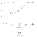
- Figure 1 (reproduced from J.J. Sullivan, C. A. Burgett, NON-LINEARITY IN CONSTANT CURRENT ELECTRON CAPTURE DETECTION, Chromatographia, Vol. 8, No. 4, April 1975), the magnitude of the non-linearity can such that the response at a low sample concentration is less than half of the response at high sample concentration.
- Nonlinear responses of this type have been previously described (cf. Sullivan & Burgett, supra; Lovelock, J. Chromatgr. 99, (1974), 3, Lovelock & Watson, J. Chromtgr. 158, (1978), 123 ; Grimsrud & Knighton, Anal. Chem. 54, (1982), 565).
- the detector response is said to be directly proportional to the instantaneous concentration of the analyte within the detector, and the response is therefore observed to lack a linear relationship to the analyte concentration entering the cell over the entire dynamic range of the detector.
- the authors describe the use of signal processing as an approach that is said to offer improved linearity for strongly responding compounds using a detector of any size or design and operated at conventional flow rates.
- the authors describe a constant current mode of control that is operated with an extended definition of the processed response; an improvement is said to occur because the alteration of analyte concentration by the attachment of electrons is accounted for and incorporated into the response function.
- the disclosed definition employs linear calibration curves for strongly electron attaching molecules over the dynamic range of the instrument, wherein the response of the detector to strongly responding compounds is taken according to the function: ( f ⁇ f 0 ) ( H + f ) / f where f is the instantaneous frequency of pulsing, f o is the baseline (or analyte-free) frequency, and H is an experimentally-determined constant.
- f the instantaneous frequency of pulsing
- f o the baseline (or analyte-free) frequency
- H is an experimentally-determined constant.
- the radioactive ionization source creates free electrons from relatively few beta particles. It is also generally held that a greater number of free electrons in the ionization cell will enable a smaller minimum detectable quantity (mdq) of the sample to be achieved. Another observation is that the emitted beta particles have a relatively long range. Accordingly, one conventional design approach is to enlarge the volume of the ionization cell, to a volume on the order of a 1.0 to 1.5 milliliters, to increase the effective level of radioactivity, thus enabling greater free electron production, and to avoid undesirable cross-section effects.
- a contrary approach to this problem is to make the ionization cell volume very small, or to make the carrier flow rate very fast, such that the residence time of the analyte in the ionization cell is then very short and ionization of the sample by the electron capture reaction is reduced.
- the reduced34 volume approach has been demonstrated by Patterson (in J. Chromatgr.134 (1977), 25), where the active volume of a small cell was made effectively smaller by use of a displaced coaxial anode.
- This invention relates generally to an electron capture detector having improved detector response, and in particular to an apparatus for improving both the linearity and sensitivity of the detector response exhibited by an electron capture detector used in a high resolution gas chromatograph.
- the "detector response factor” is considered to be the detector response per unit of sample that is subject to detection
- the "cell volume” is considered to be the volume defined by an ionization cell in an electron capture detector
- the "effective radioactivity” is considered to be the level of radioactivity induced in an ionization cell volume due to the presence of a radioactive ionization source.
- an electron capture detector having an ionization cell and a sample inlet system connected to the ionization cell for providing a fluid mixture having an electron-capturing species subject to detection in the ionization cell.
- the ionization cell includes a radioactive ionization source, preferably in the form of a radioactive foil applied to the cell interior wall.
- the ionization cell defines an optimum cell volume and is subject to an optimum effective level of radioactivity such that the electron capture reaction is forced to occur according to a concentration mode of operation.
- a cell current is measured and compared to the reference current.
- the pulse rate is then adjusted to maintain a constant cell current.
- the pulse rate varies.
- the pulse rate is converted to a voltage, which is processed by an interface according to a novel linearizing formula, and provided as the detector output signal for subsequent analysis and/or recording.
- the ionization cell volume can be substantially reduced while the aforementioned effective level of radioactivity is maintained.
- the preferred level of effective radioactivity is best effected by reducing the cell volume below that of the ionization cell volume in conventional electron capture detector.
- the optimum cell volume was found to be in the range of 100-150 microliters ( ⁇ l) for an electron capture detector having a N 63 radioactive source and operating in the range of 200-400 degrees centigrade (C.) at atmospheric pressure.
- k 1 is not constant. At higher sample concentrations, the number of free electrons become much smaller than the number of sample molecules. I have thus observed that a substantially logarithmic decay of the response factor occurs during the concentration mode, and in particular during ionization conditions wherein the number of uncaptured free electrons is much less than the number of sample molecules present in the detector ionization cell. When this happens, an increase in the sample concentration does not cause a proportionate increase in the number of free electrons. Hence, I have found that k1 should be considered to decline in logarithmic fashion as the sample concentration increases.
- Linearization of the electron capture detector may be obtained by overcoming and/or compensating for some or all the aforementioned sources of nonlinearity. This is achieved by one or both of the following: (1) forcing the detector to operate in only the concentration mode of operation, and (2) processing the signal derived from the detector response so as to compensate for the logarithmic decay of the response factor at higher sample rates.
- linearization can be achieved by providing an optimum level of effective radioactivity level in the ionization cell of the detector, thus restricting the detector operation to the concentration mode. Reducing the ionization cell volume to an optimum volume also forces the recombination constant k d to become significantly larger, thus also forcing the detector into the concentration mode.
- An optimum ionization cell volume in the range of approximately 100-150 microliters ( ⁇ l) provides a maximum effective radioactivity of approximately 1-2 millicuries and a k d sufficiently large to cause the detector to operate in the concentration mode.
- implementation of this linearizing formula can be accomplished via signal processing of the detector signal by way of a linearizing section in a detector output signal interface.
- the preferred compensation thus may be implemented in discrete electronic circuitry (i.e., in hardware), firmware, or software.
- Such linearization of the output response to account for the non-linearity of the rate constant k 1 may be applied to any ionization detector operating according to the above-described concentration mode of operation.
- This include helium ionization detector, argon ionization detector whether radioactive or nonradioactive types.
- An electron capture detector constructed according to the present invention has been observed to operate with improved sensitivity and linearity over a heretofore unrealized dynamic range (i.e., approximately six decades of sample concentration).
- the electron capture detector has demonstrated this outstanding sensitivity and linearity over a wide range of gas flow rates and detector temperatures. Neither makeup gas type, nor moderate levels of contamination, have been found to degrade the detector linearity.
- Analytical laboratories that heretofore have found difficulty in meeting the linearity requirements for government-mandated analysis of certain compounds, e.g., those found in pesticide analysis, will be able to use the teachings of this invention to operate an electron capture detector that meets the linearity requirement with great ease.
- An electron capture detector according to the present invention has also been observed to be less sensitive to contamination and thus requires less frequent cleaning. These advantages enable the electron capture detector to be operated longer, without interruption, for significant increase in sample throughput and operator productivity.
- linearity in the preferred embodiments is far less dependent on the aforementioned factors. An initial calibration will be effective for a much longer period.
- An electron capture detector preferably utilizes a smaller ionization cell volume than typically found in the prior art. Narrower chromatographic peaks are thereby detectable, and shorter chromatographic runs and high sample throughput can then be achieved.
- teachings of this invention apply to any detector operating on ionization of a fluid mixture, such as a helium ionization detector, argon ionization detector, and other electron capture detectors having either radioactive or nonradioactive electron sources.
- the apparatus and methods of the present invention may be employed in particular to improve the detection of an analyte that may be present in a variety of fluids.
- Gases are the preferred fluids according to the practice of the present invention, and therefore the following description of the invention will include a description of the arrangement, construction, and operation of a novel electron capture detector in a gas chromatographic analytical system (hereinafter, a chromatograph).
- Embodiments of the invention described herein are contemplated for use as a temperature-controlled, constant-current, pulse-modulated electron capture detector in a gas chromatograph.
- the basis for operation of the contemplated detector with respect to a chromatograph may be generally understood as follows.
- a sample is injected with a pressurized carrier gas into a separation column and the column effluent is directed as a fluid stream into the electron capture detector.
- One or more pneumatic manifold assemblies are envisioned, each of which serves in part to control and redirect a plurality of gas flows, including the carrier gas and a plurality of detector gases of appropriate types such as air, hydrogen, and make-up gas.
- the pneumatic manifold may be operated to effect a modulation of any of the aforementioned gas flows, and in particular to supply modulated purge gas flow and make-up gas flow to the electron capture detector described hereinbelow.
- Aspects of such fluid supply in the embodiments illustrated in Figures 2 et seq. is preferably provided via electronic pneumatic control (EPC).
- EPC electronic pneumatic control
- This constant also includes electrons lost by other processes, particularly those lost to cell walls
- the anode is pulsed with a narrow positive electrical pulse to momentarily collect any available free electrons in the cell.
- the pulse frequency is varied to achieve an average net current of fixed magnitude.
- the pulse frequency increases to account for the reduction in the electrons available for collection.
- the pulsing frequency is the detector output signal.
- R ( B ) Coul . f 0 ⁇ n A ⁇ n ⁇ B ( Hz molecule ⁇ 1 sec )
- Eqn.12 shows that in the prior art detectors, the response factors for different compounds are quantum in nature (because n is an integer > 1).
- this factor For a linear response over the whole dynamic range, this factor must be equal to unity. In the conventional 15 milliCurie/1500 microliter detector and for highly capturing analytes and moderate flow rates, this factor is greater than 1. For analytes with low k 1 , NL factor is less than 1. Therefore, an attempt to change the flow rate U to linearize any one analyte may cause other analytes to detected in a more non-linear fashion. Furthermore, creating calibration curves for different analytes is tedious. (Detector contamination acts like a background analyte and moves the analytes under test up and down the transition portion of the response factor curve, thus changing the response unpredictably.)
- a detector with any value of e o will theoretically work in both modes, but an important aspect is the practical limits of sample size.
- the lower limit of the sample size of course is the MDL.
- MDL detector sensitivity
- Eqn.20 is similar to eqn.2 which describes the coulometric mode of detection.
- N 2 ⁇ N ⁇ A ⁇ ⁇ f electrons / sec ( rms )
- a sh shot noise in A.
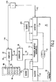
- an electron capture detector may be designed for use in an analytical instrument as shown in Figure 2.
- the instrument is generally designated chromatograph 10.
- the chromatograph 10 is a Hewlett-Packard HP6890 gas chromatograph that is modified to operate an electron capture detector according to the teachings herein.
- Operation of the chromatograph may be generally understood as follows.
- a sample is injected with a pressurized carrier gas by means of an injector 12.
- the carrier gas supplied to injector 12 is provided from a source 12A through one or more pneumatic manifold assemblies 13, each of which serves in part to control and redirect a plurality of gas flows, including the carrier gas and a plurality of detector gases of appropriate types, such as air, hydrogen, and make-up gas.
- the detector gases are provided from respective sources (one such source 24A is shown) to the pneumatic manifold assembly 13.
- Suitable fluid-handling devices such as valves, sensors and the like in the pneumatic manifold assembly 13 are operated under the control of the computer 22 and controller 26 by way of control signals provided on a data and control lines 28, 30.
- the control and data line 30 also allows the return of sense information from suitable sensors and signal-interface electronics that are provided in the pneumatic manifold assembly 13.
- Another set of data and control lines 112, 118 allows the return of detector output signal information from linearization and detector output signal interface 116 (hereinafter, interface 116) that are connected to the computer 22 and detector 24, 124.
- a column 14 is positioned within an oven 16.
- the carrier gas/sample combination passing through column 14 is exposed to a temperature profile resulting in part from the operation of a heater 18 within oven 16. During this profile of changing temperatures, the sample will separate into its components primarily due to differences in the interaction of each component with the column 14 at a given temperature.
- detector electron capture detector
- Computer 22 maintains overall control of the systems associated with gas chromatograph 10. It will be recognized that any particular gas chromatograph may include more systems than those described in relation to the present invention.
- an electronic control panel 50 is shown to include an operator interface provided in the form of a keypad 58 and a display 60. It will also be understood that although computer 22 and interface 116 are each shown as a single block, other embodiments are contemplated; for example, the functions of the computer 22 and interface 116 may be subsumed into one unit.
- the computer 22 includes a central processing unit and all associated peripheral devices, such as random access memories, read-only memories, input/output isolation devices, clocks, and the interface 116 may include a similar central processing unit or, preferably, a digital signal processing unit, and other related electronic components.
- the central processor used in computer 22 is a microprocessor.
- computer 22 and/or interface 116 may include a memory in which information and programming can be stored and retrieved by known methods.
- the programmed control of the signal processing described hereinbelow with respect to the interface 116 can be implemented by a digital computing means, such as an digital signal processor (dsp) or embedded microprocessor either of which may implement a linearization scheme as described below via firmware, or a dedicated analog network circuit incorporated in a particular detector output signal path within the interface 116.
- dsp digital signal processor
- embedded microprocessor either of which may implement a linearization scheme as described below via firmware, or a dedicated analog network circuit incorporated in a particular detector output signal path within the interface 116.
- the programming associated with the linearization scheme that is utilized in relation to the present invention will be readily understood to those skilled in the art from the linearization formula to be described below.
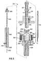
- the preferred embodiment of detector 24 is preferably constructed as an electron capture detector 200 including an upper body 210, anode 212, flow guide 220, curved washer 230, seal 240, lower body 250, and adapter 260.
- the upper body 210 is operable as a collector electrode and includes an anode tube 213 that defines a central bore 214 for accommodating the anode 212 in a spaced, concentrically located position therein.
- the flow guide 220 and an electrically insulating insert are preferably formed of high purity alumina to ensure that the anode 212 is properly positioned and electrically isolated from the upper body 210.
- the lower body 250 includes a recess 251 in an interface 252 for receiving the seal 240 and for receiving a corresponding mating surface 216 on the upper body 210.
- the lower body 250 includes a plurality of coaxially displaced, interconnected interior chambers which are in fluid communication therebetween: a central bore 254, a cap relief 255, an ionization cell 256 having therein a radioactive source 258, and anode chamber 257.
- the curved washer 230 and flow guide 220 are locatable in the anode chamber 257 such that the uppermost surface of the flow guide 220 is closely fits onto the opposing surface of the anode tube 213.
- the upper body 210 also includes a purge flow inlet 218 which communicates with the central bore 214 and a purge flow outlet 219 which communicates with the anode chamber 257.
- Hermetic sealing between the mating surfaces 216, 252 is provided by compression of the seal 240 by appropriate clamping means such as screws extending through screw bores 242 into suitable receiving means (not shown) that may be located on or in the upper body 210.
- the upper body 210, lower body 250, and certain components therein (such as the curved washer 230) are preferably constructed of inert, heat resistant material such as stainless steel.
- the adapter 260, upper body 210, and lower body 250 may be heated to a selected temperature by means (not shown) as known in the art.
- An outlet end of a chromatographic column 270 is positioned in a liner 262 and the column/liner assembly is located in the central bore 263. Gas to be analyzed, such as the effluent from the chromatographic column 270 is conducted within the column 270.
- Make-up fluid is thereafter supplied into the central bore 263 and into a central bore of the liner 262 by a make-up gas feed 264.
- a fluid mixture composed of a substantially uniform mixture of the make-up gas and the column effluent are then passed into the central bore 254 from an adapter cap 266.
- the fluid mixture exits the cap 266 and immediately enters into the ionization cell 256.
- the ionization cell 256 has a cup-shaped section with the radioactive source 258 on its side wall being so designed and positioned such that the fluid mixture can pass upwardly into the ionization cell 256 for subsequent ionization of the sample molecules that are present in the fluid mixture.
- the desired mixing of the effluent and make-up gas is preferably implemented by a mixing device provided in the form of a hollow, tubular liner 262 formed of deactivated quartz and having a flow acceleration region wherein the make-up gas and the effluent are subject to a momentary but substantial increase in velocity, thus causing turbulent flow within the flow acceleration region.
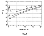
- Figure 4 is a graphical representation of the minimum detectable level (mdl) vs. effective radioactivity calculated and empirically confirmed for a prototype version of the electron capture detector of Figure 2, showing the preferred optimization of the level of effective radioactivity, according to the present invention.
- Figure 4 illustrates three curves representing the variation in the minimum detectable level (B mdl ) of a sample with respect to variations in the effective radioactivity. Curves A, B, and C were respectively calculated for flow rates of 35, 70, and 140 milliliters per minute using equation 31 (infra.).
- FIG. 5 is a representation of a preferred embodiment of the interface 116 of Figure 2.
- the interface 116 preferably includes a constant current pulse section 302, a frequency-to-current (f/I) converter 304, an analog to digital converter 306, and linearization section 308.
- Linearization of the response factor is preferably implemented so as to compensate for above-described logarithmic decay of the response factor according to a conversion table 310.
- f (lin) linearized output frequency of the electron capture detector
- f non-linearized output frequency of the electron capture detector
- f (dec) detector frequency at which k 1 begins its observed decline
- pwr power of the decline in k 1
- this linearizing formula was accomplished using firmware operating the conversion table 310 and implemented in a digital signal processor (dsp) 312.
- dsp digital signal processor
- this compensation can alternatively be accomplished in discrete electronic circuitry (i.e., in hardware), or via software operating in a microprocessor.
Landscapes
- Chemical & Material Sciences (AREA)
- Health & Medical Sciences (AREA)
- General Health & Medical Sciences (AREA)
- Life Sciences & Earth Sciences (AREA)
- Analytical Chemistry (AREA)
- Biochemistry (AREA)
- Physics & Mathematics (AREA)
- General Physics & Mathematics (AREA)
- Immunology (AREA)
- Pathology (AREA)
- Toxicology (AREA)
- Chemical Kinetics & Catalysis (AREA)
- Electrochemistry (AREA)
- Other Investigation Or Analysis Of Materials By Electrical Means (AREA)
Claims (6)
- Détecteur de capture d'électrons destiné à recevoir un mélange de fluides comportant une espèce capturant les électrons soumis à détection, comprenant :■ une cellule d'ionisation (256) définissant un volume de cellule ;■ une source d'ionisation radioactive (258) associée à ladite cellule d'ionisation pour produire une pluralité d'électrons thermiques dans ledit mélange de fluides, dans lequel l'espèce capturant les électrons présente dans le mélange de fluides peut réagir avec les électrons thermiques pour former des ions négatifs ;■ un moyen générateur de signal (124) disposé par rapport audit mélange de fluides de manière à détecter une variation subséquente de la concentration d'électrons thermiques dans le mélange de fluides, en fonction d'un facteur de réponse du détecteur et fournir un signal représentatif ; et■ un moyen de compensation de signal (116) relié audit moyen générateur de signal pour compenser une diminution logarithmique du facteur de réponse du détecteur en modifiant le signal en fonction d'une formule de linéarisation :
 où : f(lin) = fréquence de sortie linéarisée du détecteur de capture d'électronsf = fréquence de sortie non linéarisée du détecteur de capture d'électronsf (dec) = fréquence du détecteur à laquelle k1 commence sa diminution observéepwr = puissance de la diminution dans k1.
 - Détecteur de capture d'électrons selon la revendication 1, dans lequel le volume de cellule défini par la cellule d'ionisation est de façon optimale dans la plage allant de 100 à 150 microlitres.
- Détecteur de capture d'électrons selon la revendication 1, comprenant en outre un système d'entrée d'échantillon (250) relié à la cellule d'ionisation (256) pour fournir le mélange de fluides dans la cellule d'ionisation (256).
- Détecteur de capture d'électrons selon la revendication 1, dans lequel la cellule d'ionisation (256) fonctionne dans un mode de concentration.
- Détecteur de capture d'électrons selon la revendication 1, dans lequel le moyen de compensation de signal (116) comprend en outre, une table de facteurs de compensation (310) contenant divers facteurs de conversion de la formule de linéarisation.
- Détecteur de capture d'électrons selon la revendication 1, dans lequel le moyen de compensation de signal (116) comprend en outre,■ un circuit d'impulsions à courant constant (302) couplé au moyen générateur de signal (124) ;■ un convertisseur fréquence-courant (304) couplé au circuit d'impulsions à courant constant pour convertir le signal ;■ un convertisseur analogique-numérique (306) couplé au convertisseur fréquence-courant pour numériser le signal ;■ un processeur de signal numérique (312) couplé au convertisseur analogique-numérique pour modifier le signal en se basant sur la formule de linéarisation, dans lequel le processeur de signal numérique comprend en outre, une table de facteurs de compensation (310) contenant divers facteurs de conversion de la formule de linéarisation.
Applications Claiming Priority (2)
| Application Number | Priority Date | Filing Date | Title |
|---|---|---|---|
| US720478 | 1996-09-30 | ||
| US08/720,478 US5804828A (en) | 1996-09-30 | 1996-09-30 | Method and apparatus for optimizing the sensitivity and linearity of an electron capture detector |
Publications (2)
| Publication Number | Publication Date |
|---|---|
| EP0833152A1 EP0833152A1 (fr) | 1998-04-01 |
| EP0833152B1 true EP0833152B1 (fr) | 2006-03-01 |
Family
ID=24894151
Family Applications (1)
| Application Number | Title | Priority Date | Filing Date |
|---|---|---|---|
| EP97112852A Expired - Lifetime EP0833152B1 (fr) | 1996-09-30 | 1997-07-25 | Méthode et appareil pour optimiser la sensibilité et la linéarité d'un détecteur de capture d'électrons |
Country Status (4)
| Country | Link |
|---|---|
| US (1) | US5804828A (fr) |
| EP (1) | EP0833152B1 (fr) |
| JP (1) | JP3907800B2 (fr) |
| DE (1) | DE69735319T2 (fr) |
Families Citing this family (5)
| Publication number | Priority date | Publication date | Assignee | Title |
|---|---|---|---|---|
| JPH11108898A (ja) * | 1997-10-03 | 1999-04-23 | Shimadzu Corp | 電子捕獲型検出器 |
| US6163031A (en) * | 1998-04-30 | 2000-12-19 | Agilent Technologies, Inc. | Ionization detector system having linearized output signal |
| US20030085714A1 (en) * | 2001-11-05 | 2003-05-08 | Keyes Marion A. | Mass flow control in a process gas analyzer |
| JP2008232783A (ja) * | 2007-03-20 | 2008-10-02 | Shimadzu Corp | 電子捕獲型検出器 |
| CN105891396B (zh) * | 2015-01-02 | 2019-02-22 | 山东鲁南瑞虹化工仪器有限公司 | 一种气相色谱仪电捕检测器内衬装置 |
Citations (2)
| Publication number | Priority date | Publication date | Assignee | Title |
|---|---|---|---|---|
| EP0831325A1 (fr) * | 1996-09-03 | 1998-03-25 | Hewlett-Packard Company | Procédé et dispositif de discrimination d'ions dans un détecteur à capture d'électrons |
| EP0831326A1 (fr) * | 1996-09-03 | 1998-03-25 | Hewlett-Packard Company | Procédé et dispositif de discrimination d'ions dans un détecteur à capture d'électrons |
Family Cites Families (13)
| Publication number | Priority date | Publication date | Assignee | Title |
|---|---|---|---|---|
| FR1496910A (fr) * | 1965-10-18 | 1967-10-06 | Micro Tek Instr Corp | Détecteur d'ionisation |
| US3566107A (en) * | 1967-11-24 | 1971-02-23 | Hewlett Packard Co | Nickel 63 electron capture detector |
| GB1392597A (en) * | 1971-05-08 | 1975-04-30 | Lovelock J E | Electron capture detectors |
| US4063156A (en) * | 1976-02-27 | 1977-12-13 | Varian Associates, Inc. | Assymetric cylinder electron capture detector |
| US4264817A (en) * | 1979-02-27 | 1981-04-28 | Hewlett-Packard Company | Coaxial electron capture detector with thermionic emission electron source |
| US4304997A (en) * | 1979-02-27 | 1981-12-08 | Hewlett-Packard Company | Electron capture detector with thermionic emission electron source |
| US4684807A (en) * | 1983-08-11 | 1987-08-04 | Varian Associates, Inc. | Flow contoured electron capture detector cell |
| US4651008A (en) * | 1983-08-11 | 1987-03-17 | Varian Associates, Inc. | Sample inlet system for an electron capture detector |
| GB8431663D0 (en) * | 1984-12-14 | 1985-01-30 | Perkin Elmer Corp | Ionization detector |
| GB8506788D0 (en) * | 1985-03-15 | 1985-04-17 | Secr Defence | Thermal electron source |
| US4879472A (en) * | 1988-05-19 | 1989-11-07 | The United States Of America As Represented By The United States Department Of Energy | Multiplexed electronically programmable multimode ionization detector for chromatography |
| US5108466A (en) * | 1990-12-21 | 1992-04-28 | Hewlett-Packard Company | Apparatus and methods for controlling fluids provided to a chromatographic detector |
| US5479022A (en) * | 1994-06-17 | 1995-12-26 | Varian Associates, Inc. | Electron capture detector with guard electrode |
-
1996
- 1996-09-30 US US08/720,478 patent/US5804828A/en not_active Expired - Lifetime
-
1997
- 1997-07-25 DE DE69735319T patent/DE69735319T2/de not_active Expired - Lifetime
- 1997-07-25 EP EP97112852A patent/EP0833152B1/fr not_active Expired - Lifetime
- 1997-09-29 JP JP28125197A patent/JP3907800B2/ja not_active Expired - Fee Related
Patent Citations (2)
| Publication number | Priority date | Publication date | Assignee | Title |
|---|---|---|---|---|
| EP0831325A1 (fr) * | 1996-09-03 | 1998-03-25 | Hewlett-Packard Company | Procédé et dispositif de discrimination d'ions dans un détecteur à capture d'électrons |
| EP0831326A1 (fr) * | 1996-09-03 | 1998-03-25 | Hewlett-Packard Company | Procédé et dispositif de discrimination d'ions dans un détecteur à capture d'électrons |
Non-Patent Citations (2)
| Title |
|---|
| WELLS G.: "A Micro-Volume Electron Capture Detector for Use in High Resolution Capillary Column Gas Chromatography", J HIGH RES CHROMATOGR *A CHROMATOGR COMM, vol. 6, December 1983 (1983-12-01), pages 651 - 654, XP002051118 * |
| WELLS G.; SIMON R.: "Evaluation of Electron Capture Cell designs for Use in High resolution Capillary Column Gas Chromatography", J HIGH RES CHROMATOGR AND CHROMATOGR COMM, vol. 6, August 1983 (1983-08-01), pages 427 - 430, XP009030315 * |
Also Published As
| Publication number | Publication date |
|---|---|
| DE69735319D1 (de) | 2006-04-27 |
| JPH10111275A (ja) | 1998-04-28 |
| EP0833152A1 (fr) | 1998-04-01 |
| JP3907800B2 (ja) | 2007-04-18 |
| US5804828A (en) | 1998-09-08 |
| DE69735319T2 (de) | 2006-11-02 |
Similar Documents
| Publication | Publication Date | Title |
|---|---|---|
| Meier-Augenstein | Applied gas chromatography coupled to isotope ratio mass spectrometry | |
| Halasz | Concentration and Mass Flow Rate Sensitive Detectors in Gas Chromatography. | |
| Suyani et al. | Helium microwave-induced plasma mass spectrometry for capillary gas chromatographic detection: speciation of organotin compounds | |
| Condon | Design considerations of gas chromatography system employing high efficiency Golay columns | |
| Patil et al. | A brief review on gas chromatography | |
| EP0833152B1 (fr) | Méthode et appareil pour optimiser la sensibilité et la linéarité d'un détecteur de capture d'électrons | |
| Young et al. | Extending the concentration and linear dynamic range of ion mobility spectrometry with a sheath flow inlet | |
| US5739699A (en) | Method and apparatus for ion discrimination in an electron capture detector | |
| Krejči et al. | Selective detectors in gas chromatography | |
| Nelson et al. | Performace of an Instrument for Simultaneous Gas Chromatographic and Radioactivity Analysis. | |
| Goodman | Hardware modifications to an isotope ratio mass spectrometer continuous-flow interface yielding improved signal, resolution, and maintenance | |
| Priestley et al. | Determination of Subtoxic Concentrations of Phosgene in Air by Electron Capture Gas Chromatography. | |
| Sullivan et al. | Non-linearity in constant current electron capture detection | |
| US6037179A (en) | Method and apparatus for suppression of analyte diffusion in an ionization detector | |
| Clark | Quantitative determination of pesticide residues by electron absorption chromatography: Characteristics of the detector | |
| Grimsrud et al. | Stoichiometry of the reaction of electrons with bromotrichloromethane in an electron capture detector | |
| US6107805A (en) | Extended detection zone in an ionization detector | |
| Rasulev et al. | Chromatographic determination of trace amounts of amines using a surface ionization detector | |
| Bernal et al. | Characterization of an experimental TPD—MS system. Quantitative calibrations | |
| Mátyási et al. | The Effect of the Linear Velocity on the Detector Response and Effective Carbon Number: The Role of the Experimental Conditions in the Quantitative Analysis | |
| EP0831325B1 (fr) | Procédé et dispositif de discrimination d'ions dans un détecteur à capture d'électrons | |
| Yang et al. | Characteristics and performance of gas chromatographic detectors with glass capillary columns | |
| Dennison et al. | Separation and Determination of Arsenic Trichloride and Stannic Chloride by Gas Chromatography | |
| JPH11326282A (ja) | イオン化検出器 | |
| Ongkiehong | The hydrogen flame ionization detector |
Legal Events
| Date | Code | Title | Description |
|---|---|---|---|
| PUAI | Public reference made under article 153(3) epc to a published international application that has entered the european phase |
Free format text: ORIGINAL CODE: 0009012 |
|
| AK | Designated contracting states |
Kind code of ref document: A1 Designated state(s): DE FR GB |
|
| 17P | Request for examination filed |
Effective date: 19980525 |
|
| AKX | Designation fees paid |
Free format text: DE FR GB |
|
| RBV | Designated contracting states (corrected) |
Designated state(s): DE FR GB |
|
| RAP1 | Party data changed (applicant data changed or rights of an application transferred) |
Owner name: HEWLETT-PACKARD COMPANY, A DELAWARE CORPORATION |
|
| RAP1 | Party data changed (applicant data changed or rights of an application transferred) |
Owner name: AGILENT TECHNOLOGIES, INC. |
|
| RAP1 | Party data changed (applicant data changed or rights of an application transferred) |
Owner name: AGILENT TECHNOLOGIES INC. |
|
| RAP1 | Party data changed (applicant data changed or rights of an application transferred) |
Owner name: AGILENT TECHNOLOGIES INC. A DELAWARE CORPORATION |
|
| RAP1 | Party data changed (applicant data changed or rights of an application transferred) |
Owner name: AGILENT TECHNOLOGIES, INC. (A DELAWARE CORPORATION |
|
| 17Q | First examination report despatched |
Effective date: 20040517 |
|
| GRAP | Despatch of communication of intention to grant a patent |
Free format text: ORIGINAL CODE: EPIDOSNIGR1 |
|
| GRAS | Grant fee paid |
Free format text: ORIGINAL CODE: EPIDOSNIGR3 |
|
| GRAA | (expected) grant |
Free format text: ORIGINAL CODE: 0009210 |
|
| AK | Designated contracting states |
Kind code of ref document: B1 Designated state(s): DE FR GB |
|
| REG | Reference to a national code |
Ref country code: GB Ref legal event code: FG4D |
|
| REF | Corresponds to: |
Ref document number: 69735319 Country of ref document: DE Date of ref document: 20060427 Kind code of ref document: P |
|
| PGFP | Annual fee paid to national office [announced via postgrant information from national office to epo] |
Ref country code: FR Payment date: 20060717 Year of fee payment: 10 |
|
| ET | Fr: translation filed | ||
| PLBE | No opposition filed within time limit |
Free format text: ORIGINAL CODE: 0009261 |
|
| STAA | Information on the status of an ep patent application or granted ep patent |
Free format text: STATUS: NO OPPOSITION FILED WITHIN TIME LIMIT |
|
| RAP2 | Party data changed (patent owner data changed or rights of a patent transferred) |
Owner name: AGILENT TECHNOLOGIES, INC. |
|
| 26N | No opposition filed |
Effective date: 20061204 |
|
| REG | Reference to a national code |
Ref country code: FR Ref legal event code: ST Effective date: 20080331 |
|
| PG25 | Lapsed in a contracting state [announced via postgrant information from national office to epo] |
Ref country code: FR Free format text: LAPSE BECAUSE OF NON-PAYMENT OF DUE FEES Effective date: 20070731 |
|
| PGFP | Annual fee paid to national office [announced via postgrant information from national office to epo] |
Ref country code: GB Payment date: 20160720 Year of fee payment: 20 Ref country code: DE Payment date: 20160720 Year of fee payment: 20 |
|
| REG | Reference to a national code |
Ref country code: DE Ref legal event code: R071 Ref document number: 69735319 Country of ref document: DE |
|
| REG | Reference to a national code |
Ref country code: GB Ref legal event code: PE20 Expiry date: 20170724 |
|
| PG25 | Lapsed in a contracting state [announced via postgrant information from national office to epo] |
Ref country code: GB Free format text: LAPSE BECAUSE OF EXPIRATION OF PROTECTION Effective date: 20170724 |