EP0833270A2 - Verfahren und Vorrichtung zur Erfassung von auf potentiell grossflächigen Gegenständen aufgebrachten, optisch erfassbaren Informationen - Google Patents
Verfahren und Vorrichtung zur Erfassung von auf potentiell grossflächigen Gegenständen aufgebrachten, optisch erfassbaren Informationen Download PDFInfo
- Publication number
- EP0833270A2 EP0833270A2 EP97114359A EP97114359A EP0833270A2 EP 0833270 A2 EP0833270 A2 EP 0833270A2 EP 97114359 A EP97114359 A EP 97114359A EP 97114359 A EP97114359 A EP 97114359A EP 0833270 A2 EP0833270 A2 EP 0833270A2
- Authority
- EP
- European Patent Office
- Prior art keywords
- line
- camera
- information
- video camera
- line scan
- Prior art date
- Legal status (The legal status is an assumption and is not a legal conclusion. Google has not performed a legal analysis and makes no representation as to the accuracy of the status listed.)
- Granted
Links
Images



Classifications
-
- G—PHYSICS
- G06—COMPUTING OR CALCULATING; COUNTING
- G06K—GRAPHICAL DATA READING; PRESENTATION OF DATA; RECORD CARRIERS; HANDLING RECORD CARRIERS
- G06K7/00—Methods or arrangements for sensing record carriers, e.g. for reading patterns
- G06K7/10—Methods or arrangements for sensing record carriers, e.g. for reading patterns by electromagnetic radiation, e.g. optical sensing; by corpuscular radiation
- G06K7/10544—Methods or arrangements for sensing record carriers, e.g. for reading patterns by electromagnetic radiation, e.g. optical sensing; by corpuscular radiation by scanning of the records by radiation in the optical part of the electromagnetic spectrum
- G06K7/10821—Methods or arrangements for sensing record carriers, e.g. for reading patterns by electromagnetic radiation, e.g. optical sensing; by corpuscular radiation by scanning of the records by radiation in the optical part of the electromagnetic spectrum further details of bar or optical code scanning devices
- G06K7/10861—Methods or arrangements for sensing record carriers, e.g. for reading patterns by electromagnetic radiation, e.g. optical sensing; by corpuscular radiation by scanning of the records by radiation in the optical part of the electromagnetic spectrum further details of bar or optical code scanning devices sensing of data fields affixed to objects or articles, e.g. coded labels
Definitions
- the present invention relates to a method and an apparatus for detecting potentially large-area objects, optically detectable information.
- an object with a potentially large surface area is inserted into the Brought field of view of a video camera and those recognizable in the field of view of the video camera Information is integrated into one for the purpose of identification and / or assignment of the object Computer system entered.
- the corresponding device therefore has a video camera and an input device for the information from that captured by the video camera Field of view.
- the optically detectable information on the surface is used of an object often only a small part of its area, especially if it is is a very large object.
- an object from whose surface information is to be acquired actually has a large (generally flat) surface, but this area can may also be relatively small in individual cases, however, the method and the device therefor are designed, the information is essentially independent of the size of the area and itself then to grasp well and precisely if the object in question has a very large surface area while the relevant information may only be a small part of it Claim surface.
- Surface is used in the sense of the present description generally refers to the surface of an object directly facing the camera, the Distance from the camera can vary within the depth of field of the camera optics and the possibly uneven, for example more or less wavy.
- a parcel distribution system provides a typical example of corresponding methods and devices.
- parcels of various sizes are opened Delivered conveyor belts, the conveyor belts are generally designed to Packets up to a predetermined maximum size without the packets necessarily all have to be the maximum size.
- the present invention is intended not be limited to parcel distribution systems, but can also be used in production processes for Sorting and distribution systems or the like are used. The following description takes however, for the sake of better comprehensibility, mainly due to the specific example of Parcel distribution system cover.
- Packets of one can also be used individual size can be arranged on a conveyor belt, so that the camera always has the same distance from the surface of the package.
- these conventional methods are no longer applicable to the post office or other commercial courier companies that ship packages from Accept everyone or at least different customers and to a destination address promote.
- Such packages are at most standardized to the extent that they are a predetermined one Must not exceed the maximum size.
- a common standard is, for example maximum height and width of 900 mm, the length may still be this dimension can exceed.
- such packages have a cuboid shape and a flat shape Interface on which address information, information about the handling of the package or the content (risk of breakage, upward orientation during transport or storage) and Art transportation (for example express goods) are included.
- the present invention is based on the object to create a method and a device of the type mentioned, which also in Situations in which on potentially large surfaces the in a computer system too receiving information can be arranged in any areas of the surface, a remote acquisition and preferably even an automatic acquisition of this information enable.
- this object is achieved in that a high-resolution line camera is used as the video camera, the line length of which in the object distance completely covers the maximum dimensions of an object in this direction, that the object essentially transversely to the longitudinal extension of the image line at an essentially continuous speed is moved through the imaging window or the imaging plane of the line camera and that the image acquisition frequency and the feed speed of the objects are coordinated with one another in such a way that the resolution, that is to say the spacing between successive imaging lines, has at least a comparable magnitude as the resolution within an imaging line.
- the resolution between the lines could deviate by a factor between 1 and 10 from the resolution within the lines, but an embodiment of the method according to the invention is preferred in which the resolution is approximately the same in both directions.
- the orientation of the information on the surface of the object is not fixed either, so that there must be a certain, minimal resolution in each direction. Due to the use of a high-resolution line scan camera, it is possible to display a section of only 100 x 100 mm 2 in sufficient resolution, even on very large objects that have an area of 900 x 1000 mm 2 , for example, in order to display information applied to this area, For example, you can read and enter address labels in normal or fine font size.
- read and “enter” include both reading and entering a person, as well as a mechanical, automatic reading, which if necessary only is checked and confirmed by one person.
- a line scan camera with more than 1000, preferably more than 3000 and especially about 5000 to 7000 pixels along the line. How to calculate easily , 5000 pixels along an image line of, for example, 1000 mm result in a 0.2 mm resolution. This is by far sufficient for conventional inscriptions A person skilled in the art will recognize that a corresponding method also has a resolution of, for example 2000 pixels per 1 meter with a sufficiently large font still with acceptable accuracy would operate. However, a maximum line resolution of 7000 points is preferred.
- the object distance should preferably be more than twice and in particular more than that Three times the maximum width of the objects to be detected.
- This beam path can also be through one or more Mirrors, possibly also deflected by light guides or the like if this leads to Example for limiting the overall height of the overall system appears necessary or expedient
- the relatively large object distance represents a sufficient depth of field for the camera optics sure, which definitely encompasses the area within which the distance of the object surface can vary from the camera optics during the passage through the imaging plane.
- the camera optics or an imaging lens can be recorded and the distance of the line sensor in the line camera of this lens or optics is corresponding to that Distance of the object surface varies.
- a stroke of the order of 1 - 2 mm is sufficient in order to achieve an object distance of at least 3 m height differences of 800 mm in the Balance sharpness.
- the entire surface of the object or the entire partial area containing information of the same are illuminated uniformly, but it is sufficient if the object surface is homogeneously illuminated along the narrow line, which is the intersection of the The surface of the object and the level of the image results in the level of the image spanned by the optical axis of the camera and the line direction.
- the light of the lighting device focuses in this way becomes that a plane of maximum intensity the imaging plane near the surface of the Feed device or in the area of the surface of an object with a maximum distance cuts to camera, i.e. the surfaces of the lowest objects, the widest Distance to the camera are in the imaging plane and thus along the imaging line illuminated with maximum intensity.
- the imaging line has essentially the same apparent brightness, as in the case of the more distant, more intensely illuminated image line.
- the level of the maximum intensity of the lighting preferably has an angle of inclination from at least 0 °, preferably from about 10 ° to 30 ° and at most about 50 ° relative to the imaging plane, the imaging plane preferably in the same direction as that mentioned illumination plane inclined to a perpendicular to the transport surface is.
- the mapping level can be compared to a perpendicular to the transport level, for example be inclined by 20 °, the intersection between the imaging plane and the transport plane in is generally perpendicular to the direction of transport. Regardless of the inclination can however, the mapping level is also one perpendicular to the transport level small angle can be twisted so that the cut line mentioned is no longer perpendicular to Direction of transport runs.
- the simultaneous inclination of the image plane and the illumination plane serves above all Prevention of reflections captured by the camera, such as with reflecting surfaces, such as Example foils and in particular also slightly corrugated foils occur on the object surface could. Such reflections are not in the preferred inclined arrangement or captured in less disturbing form by the camera.
- An embodiment of the method is preferred in which a plurality of line scan cameras are attached to or the surfaces of objects transported on it via several feed devices capture, the line cameras via a storage device and a network with a Main computer and connected to input terminals, where the reproduced object surfaces and the ones to be extracted from them Information can be entered.
- the method according to the invention is used for a parcel distribution system intended.
- the one on which the invention is based Object achieved in that a high-resolution line camera is provided as a video camera is, the camera optics is designed or arranged so that the maximum width of a Object, seen in the direction of the line, is completely detected, and that a feed device is provided which is the object to be detected transversely to the line direction and through the imaging plane of the line scan camera with a substantially more uniform one Speed transported.
- the transport device is preferably a conveyor belt which at least the objects transported in the area of the line scan camera largely free of vibrations.
- the device is preferably designed so that the refresh rate of the Line scan camera and / or the transport speed of the feed device to one another are coordinated controllable.
- the line repetition frequency of the cell camera results in connection with the transport speed of the feed device the distance in succession Figure lines and thus also the distance and the resolution of those to be displayed accordingly Picture lines.
- the line scan camera should have a detection width of 900 mm Have a distance of more than 2 m from the surface of the objects to be imaged.
- the camera is preferably about 4 m above the surface of a conveyor belt for the Objects or arranged at a corresponding optical distance.
- the line scan camera is aligned so that it is defined above Imaging plane is aligned somewhat inclined in the direction of the band plane.
- the corresponding lighting device preferably has a light source whose light is transmitted through a focusing device is bundled in such a way that one plane (with constant distance essentially constant) maximum light intensity both to the level of the feed device and also inclined to the imaging plane of the line scan camera.
- the light source can be used for Example by a row, in the simplest case two, along a line (parallel to the image line) arranged spotlights are formed, each with its own focusing device have, so that the overlapping light intensities of the row of spotlights of the light intensity distribution come relatively close to a homogeneous, linear light source. Doing so through the focusing devices the light is bundled to one side, forming a plane maximum light intensity, i.e.
- a plane which is on the one hand from the linear Light source or the row of spotlights and on the other hand from the directional arrow is spanned in which the maximum light intensity is emitted.
- the lighting device or their focusing device with the light source are then preferably so arranged that the plane of maximum light intensity mentioned above the imaging plane cuts approximately on the surface of the transport device or somewhat above, namely at the level of the surface of an object transported on the transport device minimum height.
- this means that the object is illuminated in this way by the lighting device is that a line of maximum lighting intensity runs across the object results on both sides, i.e. to the previous and the following End of the object, gradually decreasing.
- maximum light intensity relative to the imaging plane is for higher objects the image line at a distance from the line of maximum illumination intensity and parallel to it.
- the inclination of the plane of maximum light intensity and the intensity distribution expediently set so that the lower illuminance of the image lines with higher objects by the shorter camera distance is compensated in such a way that for all objects of different heights approximately the same apparent brightness Figure line or line results.
- the angle between the imaging plane and the maximum plane Light intensity is preferably at least 10 ° and at most 50 °, this being Inclination angle, as well as the inclination of the imaging plane in the same direction contributes to the absence of distracting reflections from reflective surface areas, such as Cover films and the like, are directed into the line scan camera.
- the device according to the invention has several separate ones Feed devices on which each has its own line scan camera with a connected one Sensor computer is arranged, which in turn over a fast data network with several Processing terminals is connected. Because of the high resolution (up to 7000 pixels per Line) and fall at a line repetition frequency in the order of up to 6000 Hertz very large amounts of data, so in the preferred embodiment a data network high performance is used, such as a 100 Mbit Ethernet with a so-called "switching hub" as a switching node.
- each of the sensor computers of the line scan cameras with any of the To connect terminals.
- the number of input terminals is preferably independent of the number of line scan cameras. This feature is provided because, for example, the Acquisition and manual entry of the information data by a user takes longer than the detection of the surface of an object using the line scan camera so that the images the line scan cameras are cached and each from one of the terminals to Processing can be called up.
- the lower image processing speed at the terminals in comparison to the capture of the images by the line scan cameras this is due to a larger one Number of terminals balanced.
- the individual, captured images in the Order of their recording is cached and sent to the individual in exactly this order Terminals passed on, in the order in which the individual terminals turned out to be free report for editing a new image.
- the automatic acquisition and identification of the image information possibly run faster than the detection of the object surfaces, so that in one In such a case, the number of processing terminals could even be smaller than that of the cameras and the associated sensor computer.
- the ratio of the number of terminals to that of the cameras vary accordingly.
- each terminal shows preferably also means for rotating the image or an image detail, preferably by 90 °, by 180 ° or by 270 °, if necessary also by gradual twisting around discrete angular steps.
- each terminal has facilities for manual entry of information data, read from the terminal screen.
- an embodiment of the device according to the invention is particularly preferred which also means for automatic recording of the information data and for Displays of this automatically collected data are provided.
- the Device in addition to a bar or barcode reader also have a plain text reader, wherein with the help of a suitable program, the one saved as a digitized image in the computer Surface of the object is searched for surface areas, which apparently the contain the desired information, which is then converted into corresponding text by plain text software digital symbols are implemented and the result is then on the terminal to Example is displayed in a separate window on a screen.
- FIG. 1 A series of line scan cameras can be seen in FIG. 1, of which only four are specifically shown.
- Each of the line scan cameras contains a sensor unit, an auto focus device and one Sensor computer 11, and devices for controlling the sensors, devices for the Image processing, image processing and for communication with a host computer 2 and with Input terminals 3, these tasks at least partially by the sensor computer 11 be taken over.
- the network is e.g. B. a so-called fast Ethernet with a Transmission speed of 100 Mbit per second.
- An essential part of the network 22 forms a switching node 21, which is called “switching hub” in technical terms and which the master computer 2 is controlled and it enables each of the sensor computers 11 with each of the To connect terminals 3, whereupon each of the terminals 3 then has access to the image memory or from the host computer 2 via the switching hub 21 and the network 22 the corresponding Image data is transmitted.
- the individual surfaces captured by the cameras 1 are then as at least partially compressed image data in a buffer in the Sensor computer stored and are sent to one by the host computer 2 in the same order
- the terminals are passed on as soon as such a terminal 3 is ready for processing reports a new picture.
- the sensor computer 11 reports every complete acquisition of the image a surface 9 to the host computer 2, which then displays the images in the appropriate order forwarded to the terminals.
- Terminal 3 for example, then appears on the screen the total surface of a package and with a click of the mouse or with other control devices the user of the terminal then selects the area of the package surface, which contains the requested information.
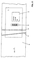
- FIG. 2 shows a corresponding surface 9 of a package with an address label 15 and a barcode field 16 shown.
- the barcode field can be read from a barcode reading program are automatically searched and read.
- the address field 15 can be enlarged on the if necessary Played screen of the terminal and the address information can by the user entered into the system via a keyboard.
- the conveyor belt 4 identifies on which the relevant package is located and, if applicable, also the information to be extracted from barcode 16 is reproduced in plain text.
- Figure 2 are still the intersection lines of two different imaging planes 10 and 10 'with the package surface 9 reproduced.
- the imaging level which is defined due to the line direction and the optical axis of the camera
- the transport plane is exactly vertical cut to the feed direction, as well as around the optical axis or a perpendicular to Transport plane can be rotated by an angle. It is also possible to change the surfaces to be captured simultaneously by two cameras, one of which is the conveyor belt perpendicular to the feed direction intersecting imaging plane 10 and the other one around has optical axis rotated relative to plane 10 imaging plane 10 '
- the two cameras are also opposite one another Perpendicular to the surface 9 or to the surface of the conveyor belt 4 inclined to this This way you can prevent light reflections that may occur from being directed into the camera.
- the beam path is the optical imaging of packets of different heights reproduced.
- the line sensor 6 which on the one hand wants to capture a high packet P1 in its entire width exactly with the entire line length, be arranged at a slightly different distance from the lens 5, if an equally wide Area to be captured sharply with a low packet P2. Because of the very large Distance of the camera lens 5 to the package surface 9 compared to the relatively small Distance between the image sensor 6 and the camera lens 5 is sufficient for the image sensor 6 Height shift of the order of 1 - 2 mm from all package surfaces 9 with Clearly map surface heights between the highest package P1 and the lowest package P2.
- the depth of field is sufficiently large to To be able to capture information from surfaces, the distance to the camera during of the passage through the imaging plane varied by a few cm. If the camera optics do not Zoom optics is so for low packets, the surface of which has a larger optical distance to the camera sensor 6 has not used the full line length or width for the image This reduces the resolution somewhat, and the line frequency to achieve the same Resolution in the feed direction is reduced accordingly.
- the height adjustment device provided for the optical focusing preferably has one Bearing plate or the like for the line sensor 6, which is at a distance from the sensor and is pivotally mounted parallel to the axis of the sensor line.
- the plate is through an eccentric drive tilts about this axis, causing the distance of the sensor from the Camera optics are changing.
- the bearing plate or the like is biased against the eccentric so that the position of the line sensor is clearly defined in every eccentric position.
- Such Furnishing is very robust, practically wear-free and when using one, for example Stepper motor as an eccentric drive with precise positioning and responsive.
- the one that occurs slight tilting of the line sensor about its longitudinal axis has no influence on it Sensitivity to light in the direction of the incident light.
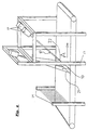
- Figure 4 shows schematically a part of a parcel distribution system consisting of a Conveyor belt 4, a height measuring device 14 and a frame 13 on which the camera 1 and a lighting device 12 are attached.
- the packages are on the conveyor belt 4 hung up and transported in the direction of arrow A. They pass through a height measuring device 14, which can consist of a large number of parallel light barriers, for example.
- the autofocus system of the line scan camera 1 reacts and sets the Distance of the image sensor 6 so that the plane of the upper surface 9 of the package P sharp is mapped.
- the light barrier height measuring device for example, one optical triangulation, an ultrasound, radar or infrared measurement can take place around the Measure distance between package surface 9 and camera optics 5.
- the lighting device 12 consists of an essentially linear light source or a linear array of spotlights with a focusing device, which directs the light from the light source onto the surface of the packets P, which is captured by the line scan camera will.
- the lighting device 12 can be a somewhat smaller distance from the Surface of the conveyor belt 4 and the surface of the objects P as the camera 1 to have.
- a lighting device with the desired intensity distribution can be realized by two spotlights arranged at a suitable distance, whose Focusing device gives the emitters a bell-shaped intensity distribution along A parallel to the line connecting the two emitters adds up their intensities a constant value at a constant distance from this line.
- the axis of the radiator and its connecting line spanned level 17 is one level maximum Illumination intensity
- the two spotlights shown in FIG. 4 can be adjusted separately in order to achieve the to be able to set optimal lighting.
- the plane 17 intersects the maximum Illumination intensity the conveyor belt 4 along a line 22 which, in the transport direction of the Seen band, lies behind the section line 21 of the imaging plane 10 with the conveyor belt 4
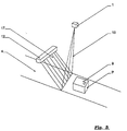
- the exact and desirable orientation of these levels 10, 17 has already been mentioned and will be explained in detail in connection with Figures 5 and 6.
- the Illumination device 12 can consist, for example, of a series of spotlights, whose light is focused and directed downwards onto the conveyor belt 4. Where the above defined plane 17 intersects a surface 9 of an object, so is the lighting intensity strongest on this surface. Along a line parallel to the series of For spotlights, the lighting intensity is constant, even with two directed in parallel Spotlights that have a bell-shaped intensity distribution around a central axis and arranged at a distance from one another which is matched to this intensity distribution the above conditions for lighting can be met in a good approximation.
- the level 17 is aligned so that the intersection of the level 17 with the level of Conveyor belt 4 as precisely as possible along the imaging line captured by the camera 1 runs, i.e. the intersection line mentioned coincides with the intersection line between imaging plane 10 and level 17 or between imaging level 10 and conveyor belt surface together.
- the intersection line 22 falls between the surface 9 of the package and the plane 17 does not coincide with the section line 21 of the surface 9 and the imaging plane 10.
- the package surface 9 is thus exposed to less light than along the parallel cutting line 22 between the package surface 9 and the plane 17 maximum Intensity of lighting.
- the higher the packet P the greater the distance between the Line of maximum lighting intensity and the imaging line 21 and accordingly lets also the intensity of the illumination of the imaging line 21 with increasing height of the packets after.
- the distance between the package surface and the camera 1 is decreasing the light-sensitive sensor 6 of the line scan camera correspondingly more light from the imaging line than at a larger distance from an imaging line (illuminated with the same intensity).
- the decrease in the intensity of the lighting in higher packages is therefore the shorter Distance to the camera is at least partially compensated and it is ultimately just a question of Inclination of level 17 and the appropriately chosen focus and intensity distribution relative to level 17 when you see the changes in brightness of the imaging line at different Package height wants to vary so that the apparent brightness of the imaging line for the line scan camera remains unchanged, i.e. the camera's light sensors per pixel and unit of time identical surfaces always absorb essentially the same amount of light quanta, when the distance of the surface from the camera is changed in the intended area. Different aperture times of the camera can also be used for different Resolutions along the transport direction are taken into account.
- This mode of operation of the lighting according to the invention is again schematic in FIG reproduced, the intensity distributions of the lighting are also shown in such a way that they each pass through the imaging line on the package surface.
- the lighting intensity of the package surface increases with increasing Distance of the package surface from the lighting device 12 decreases, but at least for the area of the imaging line 21 is overcompensated in the present case in that at a greater distance from the package surface, as in the case of package surface 2, the imaging line closer to the maximum intensity of the lighting.
- this type of lighting method and the corresponding lighting device are independent of the other features of the present invention and also Can be used for completely different purposes where it is not on detection of information arrives on potentially large surfaces, for example automatic ones Distribution and sorting systems and optical detection devices of all kinds.
Landscapes
- Physics & Mathematics (AREA)
- Engineering & Computer Science (AREA)
- Electromagnetism (AREA)
- Artificial Intelligence (AREA)
- Toxicology (AREA)
- General Health & Medical Sciences (AREA)
- Health & Medical Sciences (AREA)
- Computer Vision & Pattern Recognition (AREA)
- General Physics & Mathematics (AREA)
- Theoretical Computer Science (AREA)
- Image Input (AREA)
- Length Measuring Devices By Optical Means (AREA)
- Investigating Or Analysing Materials By Optical Means (AREA)
Abstract
Description
- Figur 1
- eine Übersicht über ein Netzwerk zwischen Zeilenkameras, Eingabeterminals und einem Leitrechner, wie es zum Beispiel für eine Paketverteilungsanlage Verwendung finden kann,
- Figur 2
- die Draufsicht auf eine Paketoberfläche mit Informationen auf einem Teil dieser Fläche,
- Figur 3
- einen Schnitt durch eine schematische Ansicht einer Videokamera in der Abbildungsebene über einem Transportband,
- Figur 4
- eine perspektivische Ansicht einer Gegenstandserfassungseinrichtung,
- Figur 5
- in perspektivischer Darstellung die relative Anordnung von Kamera und Beleuchtungssystem und
- Figur 6
- ein Schema zur Erläuterung der unterschiedlichen Beleuchtungsintensitäten bei unterschiedlichen Oberflächenhöhen.
Claims (32)
- Verfahren zur Erfassung von auf potentiell großflächigen Gegenständen aufgebrachten, optisch erfaßbaren Informationen, wobei zwecks Identifikation und/oder Zuordnung des Gegenstandes (P) der Gegenstand (P) in das Bildfeld einer Videokamera (1) gebrachtwird und die im Sichtfeld der Videokamera (1) erfaßten Informationen in ein Rechnersystem (2, 3) eingegeben werden, dadurch gekennzeichnet, daß als Videokamera eine hochauflösende Zeilenkamera (1) verwendet wird, deren Zeilenlänge im Objektabstand die Maximalabmessung eines Gegenstandes (P) in dieser Richtung vollständig abdeckt, daß der Gegenstand im wesentlichen quer zur Längserstreckung der Videobildzeile mit im wesentlichen kontinuierlicher Geschwindigkeit durch die Abbildungsebene hindurchbewegt wird, und daß die Bilderfassungsfrequenz und die Vorschubgeschwindigkeit der Gegenstände (P) derart aufeinander abgestimmt werden, daß eine mit der Auflösung innerhalb der Zeile vergleichbare Größenordnung der Auflösung zwischen aufeinanderfolgenden Zeilen erreicht wird.1
- Verfahren nach Anspruch 1, dadurch gekennzeichnet, daß eine Zeilenkamera mit mehr als 1000, vorzugsweise mehr als 3000 und insbesondere zum Beispiel 5000 oder 7000 Bildpunkten verwendet wird.
- Verfahren nach Anspruch 1 oder 2, dadurch gekennzeichnet, daß der optische Abstand zwischen Kamera (1) und Gegenstand (P) auf mehr als das Zweifache, vorzugsweise auf mehr als das Drei- oder Vierfache der maximalen Erfassungsbreite eingestellt wird.
- Verfahren nach einem der Ansprüche 1 bis 3, dadurch gekennzeichnet, daß zum Zwecke der Schärfeneinstellung der lichtempfindliche Sensor der Zeilenkamera relativ zum Objektiv (5) der Videokamera (1) bewegt wird.
- Verfahren nach einem der Ansprüche 1 bis 4, dadurch gekennzeichnet, daß aus den gespeicherten Videobilddaten eines Gegenstandes auf einem Terminal (3) ein mit optisch erfaßbaren Informationen versehener Ausschnitt (15, 16) der Oberfläche (9) des Gegenstandes (P) dargestellt wird.
- Verfahren nach einem der Ansprüche 1 bis 5, dadurch gekennzeichnet, daß die Oberfläche (9) des Gegenstandes (P) in der von der Videobildzeile und der optischen Achse der Videokamera aufgespannten Abbildungsebene mit zunehmendem Abstand der Oberfläche (9) des Gegenstandes (P) von der Videokamera gesteigert wird, und zwar derart, daß die scheinbare Helligkeit des von der Zeilenkamera erfaßten Oberflächenausschnittes in unterschiedlichen Abständen zur Zeilenkamera (1) im wesentlichen gleich ist.
- Verfahren nach Anspruch 6, dadurch gekennzeichnet, daß ein oder mehrer Beleuchtungselemente (12) verwendetwerden, welche eine in etwa glockenförmige Helligkeitsverteilung in mindestens einer Schnittebene haben, wobei die zu der Schnittebene senkrechte Ebene, welche die Achse der glockenförmigen Verteilung enthält, die Abbildungsebene in der Nähe des maximalen Objektabstandes von der Zeilenkamera schneidet.
- Verfahren nach Anspruch 7, dadurch gekennzeichnet, daß die Symmetrieebene der Intensitätsverteilung unter einem Winkel von mindestens 20° relativ zur Abbildungsebene angeordnet wird.
- Verfahren nach einem der Ansprüche 1 bis 8, dadurch gekennzeichnet, daß die in Klarschrift und/oder Barcode auf der Oberfläche (9) eines Gegenstandes (P) aufgebrachten Informationen durch eine automatische Leseeinrichtung erfaßt und in das Rechnersystem (2, 3) eingegeben werden.
- Verfahren nach einem der Ansprüche 1 bis 9, dadurch gekennzeichnet, daß gleichzeitig mehrere Zeilenkameras (1) an bzw. über mehreren Vorschubeinrichtungen (4) für Gegenstände (P) die Oberfläche der Gegenstände (P) erfassen, wobei die Zeilenkameras über ihre zugehörigen Sensorrechner und ein Netzwerk (21, 22) mit einem Leitrechner (2) und Eingabeterminals (3) verbunden sind.
- Verfahren nach Anspruch 10, dadurch gekennzeichnet, daß die erfaßten Videobilddaten der einzelnen Gegenstände in der Reihenfolge der Erfassung ihrer Oberflächen zwischengespeichert und in derselben Reihenfolge auf Abruf auf den Bildschirmen der Terminals (3) dargestellt und/oder in deren Rechnereinheit ausgewertet werden.
- Verfahren nach einem der Ansprüche 1 bis 11, dadurch gekennzeichnet, daß es für eine Paketverteilanlage verwendet wird.
- Vorrichtung zur Erfassung von auf potentiell großflächigen Gegenständen aufgebrachten, optisch erfaßbaren Informationen mit einer Videokamera (1) und einer Eingabeeinrichtung (2, 3) für Informationen aus dem von der Videokamera erfaßten Gesichtsfeld, dadurch gekennzeichnet, daß als Videokamera eine hochauflösende Zeilenkamera vorgesehen ist, wobei die Kameraoptik so ausgelegt bzw. angeordnet ist, daß die maximale Breite eines Gegenstandes, gesehen in Richtung der Zeile, vollständig erfaßt wird, und daß eine Vorschubeinrichtung vorgesehen ist, welche den zu erfassenden Gegenstand quer zur Zeilenrichtung durch deren Abbildungsebene hindurch mit im wesentlichen gleichförmiger Geschwindigkeit transportiert.
- Vorrichtung nach Anspruch 13, dadurch gekennzeichnet, daß die Bildwiederholfrequenz der Zeilenkamera (1) und/oder die Transportgeschwindigkeit der Vorschubeinrichtung (4) aufeinander abgestimmt steuerbar sind.
- Vorrichtung nach Anspruch 13 oder 14, dadurch gekennzeichnet, daß die Zeilenkamera (1) neben oder oberhalb eines Transportbandes (4) in einem optischen Abstand von mehr als dem Zweifachen, vorzugsweise bei mehr als dem Vierfachen der maximalen Erfassungsbreite der Zeilenkamera (4) angeordnet ist.
- Vorrichtung nach einem der Ansprüche 13 bis 15, dadurch gekennzeichnet, daß die von der Zeilenrichtung der Zeilenkamera (1) und einer Verbindungslinie Objekt-Zeilenkamera aufgespannte Abbildungsebene (10) leicht geneigt gegenüber einer Senkrechten zur Bandebene, vorzugsweise in Vorschubrichtung geneigt, ausgerichtet ist.
- Vorrichtung nach einem der Ansprüche 13 bis 16, dadurch gekennzeichnet, daß eine Beleuchtungseinrichtung (12) vorgesehen ist, welche eine angenähert linienförmige Lichtquelle hat, deren Licht durch eine Fokussiereinrichtung gebündelt wird, wobei eine Ebene maximaler Lichtintensität sowohl zur Ebene der Vorschubeinrichtung als auch zur Abbildungsebene (10) der Zeilenkamera (1) geneigt verläuft.
- Vorrichtung nach Anspruch 17, dadurch gekennzeichnet, daß die Beleuchtungseinrichtung (12) bzw. deren Fokussiereinrichtung und Lichtquelle derart angeordnet sind, daß die Ebene (17) maximaler Lichtintensität die Bildebene (10) in etwa auf der Oberflächenebene der Transporteinrichtung (4) oder etwas darüber schneidet.
- Vorrichtung nach Anspruch 18, dadurch gekennzeichnet, daß der Winkel zwischen der Abbildungsebene (10) und der Ebene (17) maximaler Lichtintensität mindestens 10° und höchstens 50° beträgt.
- Vorrichtung nach einem der Ansprüche 13 bis 19, dadurch gekennzeichnet, daß mehrere getrennte Vorschubeinrichtungen (4) vorgesehen sind, über welchen jeweils eine eigene Zeilenkamera (1) angeordnet ist, die wiederum über ein schnelles Datennetzwerk mit mehreren Terminals verbunden sind.
- Vorrichtung nach Anspruch 20, dadurch gekennzeichnet, daß das Datennetzwerk ein Hochgeschwindigkeitsnetzwerk ist.
- Vorrichtung nach Anspruch 21, dadurch gekennzeichnet, daß das Datennetzwerk ein ATM-Netzwerk oder ein 100 Mbit Ethernet (22), vorzugweise mit einem "Switching Hub" als Schaltknoten, ist.
- Vorrichtung nach einem der Ansprüche 20 bis 22, dadurch gekennzeichnet, daß die Anzahl der Eingabeterminals größer ist als die Anzahl der Zeilenkameras, wobei jedes Terminal mit jeder Zeilenkamera verbindbar ist.
- Vorrichtung nach einem der Ansprüche 20 bis 22, dadurch gekennzeichnet, daß die Anzahl der Eingabeterminals kleiner ist als die Anzahl der Zeilenkameras oder gleich dieser Anzahl ist, wobei jedes Terminal mit jeder Zeilenkamera verbindbar ist.
- Vorrichtung nach einem der Ansprüche 20 bis 24, dadurch gekennzeichnet, daß eine Speichereinrichtung vorgesehen ist, welche die von den Zeilenkameras (1) erfaßten, vollständigen Bilder einer Gegenstandsoberfläche (9) in der Reihenfolge der Erfassung zwischenspeichert, wobei ein zentraler Leitrechner (2) die gespeicherten Bildern einzeln in der gespeicherten Reihenfolge auf Abruf an ein Terminal (3) übergibt.
- Vorichtung nach einem der Ansprüche 13 bis 25, dadurch gekennzeichnet, daß jedes Terminal Einrichtungen zur manuellen Eingabe von Informationsdaten aufweist.
- Vorrichtung nach einem der Ansprüche 13 bis 26, dadurch gekennzeichnet, daß Einrichtungen zum Herstellen einer Ausschnittvergrößerung für den Informationen enthaltenden Bereich einer Gegenstandsoberfläche (9) vorgesehen sind.
- Vorrichtung nach einem der Ansprüche 13 bis 27, dadurch gekennzeichnet, daß Einrichtungen zum automatischen Erfassen der Informationsdaten und zum Anzeigen der automatisch erfaßten Daten vorgesehen sind.
- Vorrichtung nach einem der Ansprüche 13 bis 28, dadurch gekennzeichnet, daß ein den Sensor der Zeilenkamera tragendes Element um eine zu der Achse bzw. linearen Erstreckung des Sensors parallele Achse schwenkbar gelagert ist.
- Vorrichtung nach Anspruch 29, dadurch gekennzeichnet, daß ein an dem den Sensor tragenden Element angreifender Exzenter vorgesehen ist, durch welchen das Element in unterschiedliche Schwenkstellungen bewegbar ist.
- Vorrichtung nach Anspruch 30, dadurch gekennzeichnet, daß an dem den Sensortragenden Element eine dem Exzenter entgegenwirkende Vorspannfeder angreift.
- Verfahren nach Anspruch 4, oder einem der auf Anspruch 4 zurübezogenen Ansprüche, dadurch gekennzeichnet, daß der lichtempfindliche Sensor der Zeilenkamera um eine zu der Längserstreckung des Sensors parallele Achse verschwenkt wird.
Applications Claiming Priority (2)
| Application Number | Priority Date | Filing Date | Title |
|---|---|---|---|
| DE19639854 | 1996-09-27 | ||
| DE19639854A DE19639854A1 (de) | 1996-09-27 | 1996-09-27 | Verfahren und Vorrichtung zur Erfassung von auf potentiell großflächigen Gegenständen aufgebrachten, optisch erfaßbaren Informationen |
Publications (3)
| Publication Number | Publication Date |
|---|---|
| EP0833270A2 true EP0833270A2 (de) | 1998-04-01 |
| EP0833270A3 EP0833270A3 (de) | 2001-03-28 |
| EP0833270B1 EP0833270B1 (de) | 2005-03-23 |
Family
ID=7807143
Family Applications (1)
| Application Number | Title | Priority Date | Filing Date |
|---|---|---|---|
| EP97114359A Expired - Lifetime EP0833270B1 (de) | 1996-09-27 | 1997-08-20 | Verfahren und Vorrichtung zur Erfassung von auf potentiell grossflächigen Gegenständen aufgebrachten, optisch erfassbaren Informationen |
Country Status (6)
| Country | Link |
|---|---|
| US (1) | US6104427A (de) |
| EP (1) | EP0833270B1 (de) |
| AT (1) | ATE291760T1 (de) |
| DE (2) | DE19639854A1 (de) |
| DK (1) | DK0833270T3 (de) |
| ES (1) | ES2236772T3 (de) |
Cited By (7)
| Publication number | Priority date | Publication date | Assignee | Title |
|---|---|---|---|---|
| WO2000059648A2 (en) | 1999-04-07 | 2000-10-12 | Federal Express Corporation | System and method for dimensioning objects |
| EP1436659A4 (de) * | 2001-10-16 | 2006-03-08 | Accu Sort Systems Inc | Umskalierungsverfahren für eine lineare abbildungsvorrichtung |
| US7161688B1 (en) | 1999-08-31 | 2007-01-09 | Brett Bonner | Mass scanning and dimensioning system |
| WO2007022880A1 (de) * | 2005-08-26 | 2007-03-01 | Siemens Aktiengesellschaft | Verfahren zur identifizierung von zu sortierenden sendungen |
| EP2026249A1 (de) | 2007-08-10 | 2009-02-18 | Sick Ag | Aufnahme entzerrter Bilder bewegter Objekte mit gleichmässiger Auflösung durch Zeilensensor |
| EP2048596A1 (de) * | 2007-10-10 | 2009-04-15 | Sick Ag | Vorrichtung und Verfahren zum Aufnehmen von Bildern von auf einer Fördereinrichtung bewegten Objekten |
| DE102013110899B4 (de) | 2012-10-04 | 2019-07-04 | Cognex Corporation | Symbologie-Lesegerät mit Multicore-Prozessor und Systeme und Verfahren zum Betrieb desselben |
Families Citing this family (19)
| Publication number | Priority date | Publication date | Assignee | Title |
|---|---|---|---|---|
| US6236429B1 (en) * | 1998-01-23 | 2001-05-22 | Webview, Inc. | Visualization system and method for a web inspection assembly |
| DE19851284A1 (de) * | 1998-11-06 | 2000-05-11 | Siemens Ag | Vorrichtung zur Bildaufnahme von Paketoberflächen |
| CN1153058C (zh) * | 2000-03-29 | 2004-06-09 | 精工爱普生株式会社 | 透孔检查方法及装置 |
| EP1249415A3 (de) * | 2001-04-14 | 2004-02-04 | NexPress Solutions LLC | Verfahren und Einrichtung zur Messung von Positionen von durchlaufenden Bogen |
| JP2004519798A (ja) * | 2001-05-16 | 2004-07-02 | シーメンス アクチエンゲゼルシヤフト | 撮影装置 |
| JP4251312B2 (ja) * | 2002-03-08 | 2009-04-08 | 日本電気株式会社 | 画像入力装置 |
| US7191942B2 (en) * | 2003-01-30 | 2007-03-20 | Larry Aptekar | Transfer verification products and methods |
| WO2005048169A2 (en) * | 2003-11-14 | 2005-05-26 | Sick Auto Ident Inc. | Scanning imaging system and method for imaging articles using same |
| ATE370387T1 (de) | 2004-10-11 | 2007-09-15 | Sick Ag | Vorrichtung und verfahren zur überwachung von bewegten objekten |
| US7809158B2 (en) * | 2005-05-02 | 2010-10-05 | Siemens Industry, Inc. | Method and apparatus for detecting doubles in a singulated stream of flat articles |
| DE102006021793A1 (de) * | 2006-05-09 | 2007-11-15 | Boraglas Gmbh | Vorrichtung und Verfahren zur Erfassung und/oder Erkennung von Markierungen in/an/auf transparenten Markierungsträgern |
| US20080156619A1 (en) * | 2006-12-01 | 2008-07-03 | Mehul Patel | Range finder |
| US8629977B2 (en) | 2010-04-14 | 2014-01-14 | Digital Ally, Inc. | Traffic scanning LIDAR |
| EP2613122A4 (de) * | 2010-09-03 | 2016-12-14 | Bridgestone Corp | Verfahren und vorrichtung zur erkennung der form eines bandförmigen elements und zweidimensionaler wegsensor |
| EP2768366B1 (de) * | 2011-10-21 | 2017-04-19 | SCA Hygiene Products AB | Produktfüllstandssensor für einen produktspender |
| US10154177B2 (en) | 2012-10-04 | 2018-12-11 | Cognex Corporation | Symbology reader with multi-core processor |
| US20150037915A1 (en) * | 2013-07-31 | 2015-02-05 | Wei-Sheng Lei | Method and system for laser focus plane determination in a laser scribing process |
| TWI693578B (zh) * | 2018-10-24 | 2020-05-11 | 緯創資通股份有限公司 | 影像拼接處理方法以及其系統 |
| CN112997193A (zh) * | 2018-11-07 | 2021-06-18 | 马瑞奥三文鱼加工有限公司 | 食品加工设备和食品加工设备中提供食品对象的图像的方法 |
Family Cites Families (13)
| Publication number | Priority date | Publication date | Assignee | Title |
|---|---|---|---|---|
| JPS5891410A (ja) * | 1981-11-27 | 1983-05-31 | Olympus Optical Co Ltd | 撮像装置の合焦方法 |
| DE3204021A1 (de) * | 1982-02-05 | 1983-08-18 | Gebhardt Fördertechnik GmbH, 6920 Sinsheim | Verteileranlage fuer bewegte stueckgueter |
| DE3239938A1 (de) * | 1982-10-28 | 1984-05-03 | Licentia Patent-Verwaltungs-Gmbh, 6000 Frankfurt | Verfahren zur erkennung, identifizierung und/oder qualitaetskontrolle von gegenstaenden |
| US4776464A (en) * | 1985-06-17 | 1988-10-11 | Bae Automated Systems, Inc. | Automated article handling system and process |
| FR2723208B1 (fr) * | 1986-06-17 | 1996-11-15 | Thomson Csf | Systeme de reperage spatial d'une direction liee a un corps mobile par rapport a une structure, utilisable notamment pour un viseur de casque |
| DE4004354A1 (de) * | 1990-02-13 | 1991-08-14 | Feige Abfuelltechnik | Fassfuellmaschine fuer auf paletten stehende faesser |
| AU645123B2 (en) * | 1990-09-24 | 1994-01-06 | Fmc Corporation | Automatic windowing for article recognition |
| US5132791A (en) * | 1990-09-25 | 1992-07-21 | Ball Corporation | Optical sheet inspection system |
| DE59309558D1 (de) * | 1992-08-12 | 1999-06-10 | Siemens Ag | Verfahren und Vorrichtung zur Datenerfassung von auf Förderbahnen transportierten Gegenständen, insbesondere von Paketen |
| US5442167A (en) * | 1993-04-16 | 1995-08-15 | Intermec Corporation | Method and apparatus for automatic image focusing |
| US5365597A (en) * | 1993-06-11 | 1994-11-15 | United Parcel Service Of America, Inc. | Method and apparatus for passive autoranging using relaxation |
| US5526050A (en) * | 1994-03-31 | 1996-06-11 | Cognex Corporation | Methods and apparatus for concurrently acquiring video data from multiple video data sources |
| JP3210209B2 (ja) * | 1995-06-13 | 2001-09-17 | 松下電器産業株式会社 | 監視システム |
-
1996
- 1996-09-27 DE DE19639854A patent/DE19639854A1/de not_active Ceased
-
1997
- 1997-08-20 ES ES97114359T patent/ES2236772T3/es not_active Expired - Lifetime
- 1997-08-20 AT AT97114359T patent/ATE291760T1/de not_active IP Right Cessation
- 1997-08-20 DE DE59712240T patent/DE59712240D1/de not_active Expired - Lifetime
- 1997-08-20 DK DK97114359T patent/DK0833270T3/da active
- 1997-08-20 EP EP97114359A patent/EP0833270B1/de not_active Expired - Lifetime
- 1997-09-25 US US08/937,641 patent/US6104427A/en not_active Expired - Fee Related
Cited By (13)
| Publication number | Priority date | Publication date | Assignee | Title |
|---|---|---|---|---|
| WO2000059648A2 (en) | 1999-04-07 | 2000-10-12 | Federal Express Corporation | System and method for dimensioning objects |
| EP2272596A1 (de) * | 1999-04-07 | 2011-01-12 | Federal Express Corporation | Vorrichtung und Verfahren zur Bestimmung der Abmessungen von Objekten |
| US7137556B1 (en) | 1999-04-07 | 2006-11-21 | Brett Bracewell Bonner | System and method for dimensioning objects |
| US7161688B1 (en) | 1999-08-31 | 2007-01-09 | Brett Bonner | Mass scanning and dimensioning system |
| US7385743B2 (en) | 2001-10-16 | 2008-06-10 | Accu-Sort Systems, Inc. | Linear imager rescaling method |
| US7453614B2 (en) | 2001-10-16 | 2008-11-18 | Accu-Sort Systems, Inc. | Linear imager rescaling method |
| EP1436659A4 (de) * | 2001-10-16 | 2006-03-08 | Accu Sort Systems Inc | Umskalierungsverfahren für eine lineare abbildungsvorrichtung |
| WO2007022880A1 (de) * | 2005-08-26 | 2007-03-01 | Siemens Aktiengesellschaft | Verfahren zur identifizierung von zu sortierenden sendungen |
| EP2026249A1 (de) | 2007-08-10 | 2009-02-18 | Sick Ag | Aufnahme entzerrter Bilder bewegter Objekte mit gleichmässiger Auflösung durch Zeilensensor |
| US8360316B2 (en) | 2007-08-10 | 2013-01-29 | Sick Ag | Taking undistorted images of moved objects with uniform resolution by line sensor |
| EP2048596A1 (de) * | 2007-10-10 | 2009-04-15 | Sick Ag | Vorrichtung und Verfahren zum Aufnehmen von Bildern von auf einer Fördereinrichtung bewegten Objekten |
| US8245838B2 (en) | 2007-10-10 | 2012-08-21 | Sick Ag | Apparatus and method for the recording of images of objects moved on a conveyor device |
| DE102013110899B4 (de) | 2012-10-04 | 2019-07-04 | Cognex Corporation | Symbologie-Lesegerät mit Multicore-Prozessor und Systeme und Verfahren zum Betrieb desselben |
Also Published As
| Publication number | Publication date |
|---|---|
| EP0833270A3 (de) | 2001-03-28 |
| ATE291760T1 (de) | 2005-04-15 |
| DK0833270T3 (da) | 2005-06-06 |
| ES2236772T3 (es) | 2005-07-16 |
| DE59712240D1 (de) | 2005-04-28 |
| EP0833270B1 (de) | 2005-03-23 |
| US6104427A (en) | 2000-08-15 |
| DE19639854A1 (de) | 1998-06-10 |
Similar Documents
| Publication | Publication Date | Title |
|---|---|---|
| EP0833270B1 (de) | Verfahren und Vorrichtung zur Erfassung von auf potentiell grossflächigen Gegenständen aufgebrachten, optisch erfassbaren Informationen | |
| DE19544178B4 (de) | Vorrichtung zum scannenden Digitalisieren von Bildvorlagen sowie Verfahren zu deren Betrieb | |
| DE69609085T2 (de) | Sichtsystem mit mehreren brennpunkten | |
| DE69600461T2 (de) | System und Verfahren zur Bewertung der Abbildung eines Formulars | |
| EP1645839B1 (de) | Vorrichtung und Verfahren zur Überwachung von bewegten Objekten | |
| DE69834053T2 (de) | Ccd-basierter bar-kode-scanner | |
| DE3926349C2 (de) | ||
| WO1991009688A1 (de) | Verfahren zum verteilen von paketen o.ä. | |
| DE69419277T2 (de) | Gerät für die Untersuchung eines Bodenrandbereiches eines transparenten Glasbehälters | |
| EP0858055A2 (de) | Vorrichtung zur Vermessung von Poststücken | |
| DE4305559A1 (de) | Anordnung und Verfahren zur Konturerkennung von Gegenständen | |
| DE69429114T2 (de) | Automatisches holzbündelregistriersystem und verfahren | |
| CH686207A5 (de) | Verfahren und Einrichtung zum Erzeugen eines Bilds hoher Auflosung. | |
| DE4212404A1 (de) | Vorrichtung zum messen der raeumlichen form eines langgestreckten bauteils | |
| WO1989008836A1 (fr) | Procede et dispositif de detection de defauts dans des pieces embouties a la piece ou dans d'autres pieces a usiner | |
| EP1152873A1 (de) | Verfahren und vorrichtung zum abtrennen scheibenförmiger körper von einem ursprungskörper | |
| DE19509631A1 (de) | Verfahren und Einrichtung zum Erkennen und Sortieren von Getränkebehältern, insbesondere Flaschen und Flaschenkästen | |
| EP2556006B1 (de) | Verfahren und vorrichtung zum geregelten transportieren von mehreren gegenständen | |
| EP1022541A2 (de) | Verfahren und Vorrichtung zur Bestimmung der Geometrie von blattförmigem Gut oder Stapeln davon | |
| DE202006020599U1 (de) | Optische Erfassung von bewegten Objekten und Vorrichtung | |
| EP1925921B1 (de) | Verfahren und Vorrichtung zur Bestimmung der Masse von Stückgut auf einer Fördereinrichtung | |
| DE102015101144A1 (de) | Pack-Wägestation mit Volumenerkennung und Verfahren | |
| DE4001298A1 (de) | Verfahren zur dreidimensionalen lichtoptischen vermessung von objekten und vorrichtung zur durchfuehrung des verfahrens | |
| DE4025682C2 (de) | ||
| EP1124651B1 (de) | Vorrichtung zur bildaufnahme von paketoberflächen |
Legal Events
| Date | Code | Title | Description |
|---|---|---|---|
| PUAI | Public reference made under article 153(3) epc to a published international application that has entered the european phase |
Free format text: ORIGINAL CODE: 0009012 |
|
| AK | Designated contracting states |
Kind code of ref document: A2 Designated state(s): AT BE CH DE DK ES FR GB IT LI LU NL SE |
|
| 17P | Request for examination filed |
Effective date: 19980901 |
|
| PUAL | Search report despatched |
Free format text: ORIGINAL CODE: 0009013 |
|
| AK | Designated contracting states |
Kind code of ref document: A3 Designated state(s): AT BE CH DE DK ES FI FR GB GR IE IT LI LU MC NL PT SE |
|
| AKX | Designation fees paid |
Free format text: AT BE CH DE DK ES FR GB IT LI LU NL SE |
|
| 17Q | First examination report despatched |
Effective date: 20030305 |
|
| GRAP | Despatch of communication of intention to grant a patent |
Free format text: ORIGINAL CODE: EPIDOSNIGR1 |
|
| GRAS | Grant fee paid |
Free format text: ORIGINAL CODE: EPIDOSNIGR3 |
|
| GRAA | (expected) grant |
Free format text: ORIGINAL CODE: 0009210 |
|
| AK | Designated contracting states |
Kind code of ref document: B1 Designated state(s): AT BE CH DE DK ES FR GB IT LI LU NL SE |
|
| REG | Reference to a national code |
Ref country code: GB Ref legal event code: FG4D Free format text: NOT ENGLISH |
|
| REG | Reference to a national code |
Ref country code: CH Ref legal event code: EP |
|
| REF | Corresponds to: |
Ref document number: 59712240 Country of ref document: DE Date of ref document: 20050428 Kind code of ref document: P |
|
| REG | Reference to a national code |
Ref country code: CH Ref legal event code: NV Representative=s name: ISLER & PEDRAZZINI AG |
|
| REG | Reference to a national code |
Ref country code: SE Ref legal event code: TRGR |
|
| GBT | Gb: translation of ep patent filed (gb section 77(6)(a)/1977) |
Effective date: 20050509 |
|
| REG | Reference to a national code |
Ref country code: DK Ref legal event code: T3 |
|
| REG | Reference to a national code |
Ref country code: ES Ref legal event code: FG2A Ref document number: 2236772 Country of ref document: ES Kind code of ref document: T3 |
|
| PGFP | Annual fee paid to national office [announced via postgrant information from national office to epo] |
Ref country code: GB Payment date: 20050808 Year of fee payment: 9 |
|
| PGFP | Annual fee paid to national office [announced via postgrant information from national office to epo] |
Ref country code: NL Payment date: 20050812 Year of fee payment: 9 Ref country code: FR Payment date: 20050812 Year of fee payment: 9 Ref country code: DK Payment date: 20050812 Year of fee payment: 9 Ref country code: CH Payment date: 20050812 Year of fee payment: 9 |
|
| PGFP | Annual fee paid to national office [announced via postgrant information from national office to epo] |
Ref country code: ES Payment date: 20050816 Year of fee payment: 9 Ref country code: AT Payment date: 20050816 Year of fee payment: 9 |
|
| PGFP | Annual fee paid to national office [announced via postgrant information from national office to epo] |
Ref country code: LU Payment date: 20050822 Year of fee payment: 9 |
|
| PGFP | Annual fee paid to national office [announced via postgrant information from national office to epo] |
Ref country code: BE Payment date: 20050914 Year of fee payment: 9 |
|
| ET | Fr: translation filed | ||
| PLBE | No opposition filed within time limit |
Free format text: ORIGINAL CODE: 0009261 |
|
| STAA | Information on the status of an ep patent application or granted ep patent |
Free format text: STATUS: NO OPPOSITION FILED WITHIN TIME LIMIT |
|
| 26N | No opposition filed |
Effective date: 20051227 |
|
| PG25 | Lapsed in a contracting state [announced via postgrant information from national office to epo] |
Ref country code: AT Free format text: LAPSE BECAUSE OF NON-PAYMENT OF DUE FEES Effective date: 20060820 |
|
| PG25 | Lapsed in a contracting state [announced via postgrant information from national office to epo] |
Ref country code: SE Free format text: LAPSE BECAUSE OF NON-PAYMENT OF DUE FEES Effective date: 20060821 |
|
| PG25 | Lapsed in a contracting state [announced via postgrant information from national office to epo] |
Ref country code: LI Free format text: LAPSE BECAUSE OF NON-PAYMENT OF DUE FEES Effective date: 20060831 Ref country code: DK Free format text: LAPSE BECAUSE OF NON-PAYMENT OF DUE FEES Effective date: 20060831 Ref country code: CH Free format text: LAPSE BECAUSE OF NON-PAYMENT OF DUE FEES Effective date: 20060831 Ref country code: BE Free format text: LAPSE BECAUSE OF NON-PAYMENT OF DUE FEES Effective date: 20060831 |
|
| PG25 | Lapsed in a contracting state [announced via postgrant information from national office to epo] |
Ref country code: NL Free format text: LAPSE BECAUSE OF NON-PAYMENT OF DUE FEES Effective date: 20070301 |
|
| REG | Reference to a national code |
Ref country code: DK Ref legal event code: EBP |
|
| REG | Reference to a national code |
Ref country code: CH Ref legal event code: PL |
|
| EUG | Se: european patent has lapsed | ||
| GBPC | Gb: european patent ceased through non-payment of renewal fee |
Effective date: 20060820 |
|
| NLV4 | Nl: lapsed or anulled due to non-payment of the annual fee |
Effective date: 20070301 |
|
| REG | Reference to a national code |
Ref country code: FR Ref legal event code: ST Effective date: 20070430 |
|
| REG | Reference to a national code |
Ref country code: ES Ref legal event code: FD2A Effective date: 20060821 |
|
| PG25 | Lapsed in a contracting state [announced via postgrant information from national office to epo] |
Ref country code: GB Free format text: LAPSE BECAUSE OF NON-PAYMENT OF DUE FEES Effective date: 20060820 |
|
| BERE | Be: lapsed |
Owner name: *VITRONIC DR.-ING. STEIN BILDVERARBEITUNGSSYSTEME Effective date: 20060831 |
|
| PG25 | Lapsed in a contracting state [announced via postgrant information from national office to epo] |
Ref country code: ES Free format text: LAPSE BECAUSE OF NON-PAYMENT OF DUE FEES Effective date: 20060821 |
|
| PG25 | Lapsed in a contracting state [announced via postgrant information from national office to epo] |
Ref country code: FR Free format text: LAPSE BECAUSE OF NON-PAYMENT OF DUE FEES Effective date: 20060831 |
|
| PG25 | Lapsed in a contracting state [announced via postgrant information from national office to epo] |
Ref country code: LU Free format text: LAPSE BECAUSE OF NON-PAYMENT OF DUE FEES Effective date: 20060820 |
|
| PGFP | Annual fee paid to national office [announced via postgrant information from national office to epo] |
Ref country code: IT Payment date: 20100226 Year of fee payment: 13 |
|
| PGFP | Annual fee paid to national office [announced via postgrant information from national office to epo] |
Ref country code: DE Payment date: 20100226 Year of fee payment: 13 |
|
| PG25 | Lapsed in a contracting state [announced via postgrant information from national office to epo] |
Ref country code: IT Free format text: LAPSE BECAUSE OF NON-PAYMENT OF DUE FEES Effective date: 20100820 |
|
| REG | Reference to a national code |
Ref country code: DE Ref legal event code: R119 Ref document number: 59712240 Country of ref document: DE Effective date: 20110301 |
|
| PG25 | Lapsed in a contracting state [announced via postgrant information from national office to epo] |
Ref country code: DE Free format text: LAPSE BECAUSE OF NON-PAYMENT OF DUE FEES Effective date: 20110301 |