EP0833276A2 - Système et appareil de formation d'images - Google Patents
Système et appareil de formation d'images Download PDFInfo
- Publication number
- EP0833276A2 EP0833276A2 EP97116989A EP97116989A EP0833276A2 EP 0833276 A2 EP0833276 A2 EP 0833276A2 EP 97116989 A EP97116989 A EP 97116989A EP 97116989 A EP97116989 A EP 97116989A EP 0833276 A2 EP0833276 A2 EP 0833276A2
- Authority
- EP
- European Patent Office
- Prior art keywords
- section
- identification code
- image forming
- forming apparatus
- Prior art date
- Legal status (The legal status is an assumption and is not a legal conclusion. Google has not performed a legal analysis and makes no representation as to the accuracy of the status listed.)
- Granted
Links
Images







Classifications
-
- G—PHYSICS
- G06—COMPUTING OR CALCULATING; COUNTING
- G06K—GRAPHICAL DATA READING; PRESENTATION OF DATA; RECORD CARRIERS; HANDLING RECORD CARRIERS
- G06K17/00—Methods or arrangements for effecting co-operative working between equipments covered by two or more of main groups G06K1/00 - G06K15/00, e.g. automatic card files incorporating conveying and reading operations
-
- G—PHYSICS
- G06—COMPUTING OR CALCULATING; COUNTING
- G06K—GRAPHICAL DATA READING; PRESENTATION OF DATA; RECORD CARRIERS; HANDLING RECORD CARRIERS
- G06K15/00—Arrangements for producing a permanent visual presentation of the output data, e.g. computer output printers
- G06K15/02—Arrangements for producing a permanent visual presentation of the output data, e.g. computer output printers using printers
-
- G—PHYSICS
- G06—COMPUTING OR CALCULATING; COUNTING
- G06K—GRAPHICAL DATA READING; PRESENTATION OF DATA; RECORD CARRIERS; HANDLING RECORD CARRIERS
- G06K2215/00—Arrangements for producing a permanent visual presentation of the output data
- G06K2215/0082—Architecture adapted for a particular function
Definitions
- This invention relates to an image forming apparatus, typified by printers, for receiving image data, which is printable data including characters, figures, symbols, lines or the like, from external machines, converting the received image data into a print image, and printing the image.
- image data which is printable data including characters, figures, symbols, lines or the like
- This invention relates to an image forming system comprising: an external machine, typified by personal computers, for preparing image data; and an image forming unit, typified by printers, for receiving image data from and the external machine, converting the received image data into a print image, and printing the image.
- This invention relates to an image forming system comprising: an information processing unit, typified by a personal computer, for preparing image data; an image forming unit, typified by a printer, for receiving image data from the information processing unit, converting the received image data into a print image and printing the image; and a terminal adapter unit for executing speed conversion and protocol conversion and conducting wireless or wire data communication with external machines.
- a printer of a conventional image forming unit Upon reception of image data from an external machine such as a personal computer or a host computer, a printer of a conventional image forming unit forms a print image based on the received image data and prints as many copies as instructed from the external machine, etc.
- FIG. 26 is a schematic block diagram to show a conventional image forming unit.
- An image forming unit 21 comprises an I/F section 22 for receiving image data from an external system, a data conversion section 23 for converting the image data received on the I/F section into print data, a storage section 24 for storing programs required for controlling the image forming unit 21, font data required for the data conversion section 23, and the like, a printing section 25 for printing the data from the data conversion section 23, and a control section 26 for controlling these sections.
- the conventional image forming unit erases all data involved in the printing.
- the print command must be again issued from the information processing unit. If the image data is not stored in a floppy disk, a hard disk, or the like, the printed paper must be copied by a copy machine. Alternatively, to make the best use of a high resolution, the print data must be again created from the beginning at the information processing unit.
- an image forming apparatus for printing external-image data comprises an identification code assignment section for assigning an identification code for each page unit or print job unit of print images, a printing section for printing the print image and its corresponding identification code on a recording medium, a storage section for storing the print images and their corresponding identification codes, and an identification code read section for reading the identification code printed on the recording medium.
- the print image corresponding to the identification code read through said identification code read section is taken out from said storage section and the print image or the print image and the identification code are printed on a recording medium in said printing section.
- FIG. 1 is a schematic block diagram to show an image forming apparatus according to the invention.
- An image forming apparatus 1 comprises an I/F section 2, a data conversion section 3, a storage section 4, a printing section 5, a control section 6, an identification code assignment section 7, and an identification code read section 8.
- the I/F section 2 is connected to a computer or the like, via a cable to receive image data to be printed from the computer.
- the data conversion section 3 converts the image data received at the I/F section 2 into data that can be printed in the printing section 5.
- the identification code assignment section 7 assigns an identification code in relation with a print image for each page or each print job unit (namely, file unit).
- the information contained in the identification code may be the serial number of the image forming apparatus 1, the serial number of the document, a password, etc. These information pieces may be compressed, encoded, and assigned as a bar code, for example.
- the storage section 4 is a section for storing programs required for controlling the entire image forming apparatus 1, font data required for the data conversion section 3, print images printed in the printing section 5, and identification codes in a one-to-one correspondence with print images for each page unit or print job unit, assigned by the identification code assignment section 7.
- the printing section 5 prints the data provided by the data conversion section 3 on a recording medium, and also prints the identification code assigned by the identification code assignment section 7 on the recording medium at the same time.
- the control section 6 is a section for controlling the entire image forming apparatus 1.
- the identification code read section 8 reads the identification code printed on a recording medium; it may be a bar-code reader if the identification code is indicated like a bar code.
- a print image and an identification code are printed-on a recording medium and at the same time, and they are also stored in the storage section 4.
- the identification code printed on the recording medium is simply read through the identification code read section 8, whereby the print image can be taken out from the storage section 4 and can be printed any number of times.
- the identification code may be printed as following manners: (Which print manner is adopted may be previously specified or the image forming apparatus may be provided with selection means for selecting any one of the print methods or a combination thereof.)
- every recording medium of print can be read through the identification code read section 8.
- the image forming apparatus of the invention is provided with network control means capable of also accessing other external machines and read and output means capable of reading and outputting print images of other units, documents of other image forming apparatus can also be drawn out and print images can be shared because the serial number of each image forming apparatus is contained in the identification code. If at least the serial number is printed in an alphanumeric character string, etc., and the correspondence between the alphanumeric strings as the serial numbers and the image forming apparatus is indicated, which image forming apparatus the print document is printed at is known and if the identification code is read through the identification code read section 8 of the image forming apparatus, the document can be printed promptly.
- the image forming apparatus is connected to a host computer, etc., and is provided with means that can respond to search, retrieval, and output instructions from the host computer, etc., the host computer can manage files and list the stored print image contents.
- the image forming apparatus is provided with means that can respond to setting of copy protect from the host computer, etc., the security of print images can be maintained.
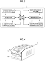
- FIGS. 2 and 3 are reference drawings to explain a printer according to a first embodiment of the image forming apparatus of the invention.
- FIG. 2 is a perspective view of a printer 1.
- the printer 1 comprises the main components of an I/F section (interface section) 2, a data conversion section 3, a storage section 4, a printing section 5, a control section 6, an identification code assignment section 7, and an identification code read section 8, as shown in Figure 3.
- the identification code read section 8 is a section for reading an identification code printed on recording paper 10; it may be made of a bar-code reader if the identification code is a code like a bar code 10a. In the first embodiment, such a bar-code reader is placed facing the inside of a slit 1a made in a part of the outside of the printer 1, as shown in Figure 2. The recording paper 10 is passed through the slit 1a, whereby the bar-code reader can read the bar code 10a printed on the recording paper 10.
- the bar-code reader is a sensor for executing photoelectric conversion of the bar code 10a and reading the conversion result.
- a bar code is irradiated with laser light, infrared light, etc., and the sensor reads the reflected light from the bar code, executes photoelectric conversion, and determines the bar code contents electrically.
- a system for scanning a narrowed light source over a bar code and reading the reflected light from the bar code by a sensor includes laser scanning, flying spot, etc., for example.
- a system using a self-scanning sensor having a large number of pixels to read bar codes includes CCDs, a photodiode array, etc., for example.
- the system for moving the bar code 10a (recording paper 10), irradiating the bar code 10a with laser light, etc., and reading the reflected light from the bar code, the camera system using CCDs, etc., to read the whole bar code 10a in batch, etc. can be used as the bar-code reader in the first embodiment; any of the above-mentioned systems may be used as the read system and in this point, the same also applies to the following embodiments.
- the printer 1 according to the first embodiment can print any number of times simply by passing the recording paper 10 through the slit 1a, thus can print not via an external machine; printing is enabled in a short time and the operability of the printer 1 can be improved remarkably.
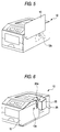
- Figure 4 is an illustration to show a printer 11 according to a second embodiment of the invention.
- the second embodiment differs from the first embodiment in that a bar-code reader (identification code read section 8) is disposed in a part of a feed passage of recording paper 10 fed from a manual paper feed section 11a in the second embodiment.
- a bar-code reader identification code read section 8
- the recording paper 10 is fed into the manual paper feed section 11a, whereby the bar-code reader reads a bar code 10a and the print image corresponding to the read bar code can be taken out from a storage section 4 and again printed.
- printing is enabled not via an external machine, thus the printer 11 can print in a short time and the operability of the printer 11 can be improved remarkably.
- the system for moving the bar code 10a, irradiating the bar code 10a with laser light, etc., and reading the reflected light from the bar code, the camera system using CCDs, etc., or the like can be used as the bar-code reader as in the first embodiment; any other read system may be used as described above if it can be applied.
- FIG. 5 is an illustration to show a printer 12 according to a third embodiment of the invention.
- a bar-code reader 12a (identification code read section 8) is disposed in a part of the outside of the printer 12 and a bar code 10a of recording paper 10 is made to approach so as to cover the bar-code reader 12a, whereby the bar-code reader 12a reads the bar code 10a and the print image corresponding to the bar code 10a can be again printed.
- printing is enabled not via an external machine, thus the printer 12 can print in a short time and the operability of the printer 12 can be improved remarkably.
- the camera system can be used as the bar-code reader 12a; any other read system may be used as described above if it can be applied.
- Figures 6 and 7 are drawings to show a printer 13 according to a fourth embodiment of the invention.
- the identification code read section 8 is integral with the printer 1, 11, 12.
- a bar-code reader 25 (identification code read section 8) is separately disposed on the outside of the printer 13, is connected to the printer 13 via wiring 26, and is formed with a slit 25a through which recording paper 10 on which a bar code 10a to be read is printed is passed.
- printing is enabled hot via an external machine, thus the printer 13 can print in a short time and the operability of the printer 13 can be improved remarkably.
- the system for moving the bar coded 10a or the camera system can be used as the bar-code reader 25; any other read system may be used as described above if it can be applied.
- FIG. 8 is an illustration to show a printer 14 according to a fifth embodiment of the invention.
- a pen holder (pen member) 28 provided at a tip with a bar-code reader 28a (identification code read section 8) is connected to the printer 14 via wiring 26.
- the pen holder 28 containing the bar-code reader 28a is slid on a bar code 10a of recording paper 10 in a direction perpendicular to the line of the bar code 10a, whereby the bar code 10a can be read from end to end in order and the print image corresponding to the bar code 10a can be printed again.
- printing is enabled not via an external machine, so that the printer 14 can print in a short time and the operability of the printer 14 can be improved remarkably.
- a manual scanning system for the user to hold the pen holder 28 and scan over the bar code 10a by the bar code reader 28a is used; any other read system may be used as described above if it can be applied.
- Figure 9 is an illustration to show a printer 15 according to a sixth embodiment of the invention.
- a bar-code reader 30 (identification code read section 8) is connected to the printer 15 via wiring 26.
- the bar-code reader 30 is slid on a bar code 10a of recording paper 10 in the length direction of the line of the bar code 10a, whereby the bar code 10a can be read in batch and the print image corresponding to the bar code 10a can be printed again.
- printing is enabled not via an external machine, so that the printer 15 can print in a short time and the operability of the printer 15 can be improved remarkably.
- a system for scanning infrared light, etc., over the bar code 10a or the camera system can be used as the bar-code reader 30; any other read system may be used as described above if it can be applied.
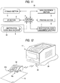
- FIGS. 10 and 11 are drawings to show a printer 16 according to a seventh embodiment of the invention.
- a bar-code reader 32 used with the printer 16 has a slit 32a through which recording paper 10 is passed to read a bar code 10a, but is not connected to the printer 16 via wiring 26, etc.,; a read signal of the bar code 10a is input to the printer 16 via an internal antenna 34, etc., of the printer 16 as a radio signal.
- printing is enabled not via an external machine, thus the printer 16 can print in a short time and the operability of the printer 16 can be improved remarkably.
- the system for moving the bar code 10a or the camera system can be used as the bar-code reader 30; any other read system may be used as described above if it can be applied.
- FIG 12 is an illustration to show a printer 17 according to an eighth embodiment of the invention.
- the eighth embodiment differs from the seventh embodiment in that an external receiver 36 connected to the printer 17 via wiring 26 receives a radio signal from a bar-code reader 32 in the eighth embodiment; whereas, the signal of the bar code 10a is input via the internal antenna 34, etc., of the printer 16 as a radio signal from the bar-code reader 32 in the seventh embodiment.
- the recording paper 10 namely, paper is used as a flexible sheet material.
- any sheet material other than paper such as a plastic sheet material, can also be used if it is a flexible and sturdy material like a sheet.
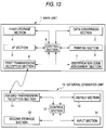
- FIG. 13 is a schematic block diagram to show an image forming apparatus according to a ninth embodiment of the invention.
- the image forming apparatus comprises a main unit 1 and an external operation unit 10.
- the main unit 1 is provided with an I/F section 2, a data conversion section 3, a first storage section 4, a printing section 5, a control section 6, an identification code assignment section 7, and a first transmission/reception section 8.
- the external operation unit 10 is provided with a second transmission/reception section 11, a second storage section 12, a display section 13, an input section 14, and a control section 15.
- the I/F section 2 is a section being connected to a computer, etc., via a cable for receiving image data to be printed from the computer, etc.
- the data conversion section 3 is a section for converting the image data received at the I/F section 2 into data that can be printed in the printing section 5.
- the identification code assignment section 7 is a section for assigning an identification code in relation with a print image for each page unit or print job unit (namely, file unit).
- the information contained in the identification code may be the serial number of a printer, the serial number of the document, a password, etc. These information pieces may be assigned in an alphanumeric character string, etc.
- the first storage section 4 is a section for storing programs required for controlling the entire main unit 1, font, etc., required for the data conversion section 3, print images printed in the printing section 5, and identification codes corresponding to the print images, assigned by the identification code assignment section 7.
- the printing section 5 is a section for printing the data provided by the data conversion section 3 and the identification code assigned by the identification code assignment section 7 on a recording medium at the same time.
- the control section 6 is a section for controlling the entire main unit 1.
- the first transmission/reception section 8 and the second transmission/reception section 11 are sections that can transmit and receive data such as identification codes to and from each other by a wireless communication method of infrared rays, radio wave, etc.
- the second storage section 12 is a section for storing programs required for controlling the entire external operation unit 10 and data such as identification codes received at the second transmission/reception section 11.
- the display section 13 is a section for displaying characters and digits; it can display identification codes.
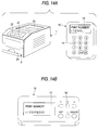
- the input section 14 is a section for entering identification codes; it may be made up of ten keys, character entry enabling keys, an enter button, etc., as shown in Figure 14A.
- a print image and an identification code are printed on a recording medium and at the same time, are stored in the first storage section 4.
- the identification code printed on the recording medium is simply entered through the input section 8 or the identification code stored in the second storage section 12 is simply displayed on the display section 13 and then an input command is given (in the embodiment, the enter button is pressed), whereby the print image can be taken out from the first storage section 4 via the second reception/transmission section 11 and the first reception/transmission section 8; it can be printed any number of times.
- Figure 14A is a schematic perspective view of the main unit 1.
- the main unit 1 has an operation panel 21, a display section 22, a tray 23 as a cassette paper feed section, a cassette 24, and a recording medium discharge section 25 on appearance. Further, it comprises the first transmission/reception section 8 on the front.
- the identification code may be printed as follows: (Which print method is adopted may be previously specified or the main unit or the external operation unit may be provided with selection means for selecting any one of the print methods or a combination thereof.)
- a print command can be entered for every recording medium of print.
- the image forming apparatus of the invention is provided with network control means capable of also accessing other external machines and read and output means capable of reading and outputting print images of other units, documents of other image forming apparatus can also be drawn out and print images can be shared because the serial number of each image forming apparatus is contained in the identification code. If the correspondence between the alphanumeric strings as the serial numbers and the image forming apparatus is indicated, which image forming apparatus the document is printed at is known and if the identification code is entered on the external operation unit of the image forming apparatus, the document can be printed promptly. If the image forming apparatus is connected to a host, etc., and is provided with means that can respond to retrieval, read, and output instructions from the host, etc., the host can manage files and list the stored print image contents. If the image forming apparatus is provided with means that can respond to setting of copy protect from the host, etc., the security of print images can be maintained.
- related information to the print image corresponding to an identification code together with the identification code is transferred between a first transmission/reception section 8 and a second transmission/reception section 11 and is stored in a second storage section 12, then the identification code and the related information may be displayed on a display section 13. In doing so, rough information on the print image corresponding to the identification code can be known without seeing the recording medium and the time to printing can be reduced drastically.
- the tenth embodiment differs from the ninth embodiment in the following points:
- identification code is not printed on recording media and is not entered through the input section 14
- the identification code stored in the second storage section 12 can be displayed on the display section 13, so that similar effects to those of the invention can be produced.
- FIG. 15 is a schematic block diagram to show an image forming apparatus of the invention.
- the image forming apparatus comprises a main unit 1 and an external operation unit 11.
- the main unit 1 is provided with an I/F section 2, a data conversion section 3, a storage section 4, a printing section 5, a control section 6, an identification code assignment section 7, a card insertion section 8, and a reception section 9.
- the external operation unit 11 is provided with a display section 13, a selection section 14, a control section 16, a card insertion section 18, and a transmission section 19.
- the I/F section 2 is a section being connected to an external machine (not shown) such as a computer via a cable or in a wireless manner for receiving image data to be printed from the external machine.
- an external machine such as a computer
- the data conversion section 3 is a section for converting the image data received at the I/F section 2 into data that can be printed in the printing section 5.
- the identification code assignment section 7 is a section for assigning an identification code in relation with a print image for each page unit or print job unit (namely, file unit).
- the information contained in the identification code may be the serial number of a printer, the serial number of the document, a password, etc. These information pieces may be assigned in characters, digits, or symbols, or a combination thereof, etc.
- the storage section 4 is a section for storing programs required for controlling the entire main unit 1, font, etc., required for the data conversion section 3, print images printed in the printing section 5, and identification codes corresponding to the print images, assigned by the identification code assignment section 7.
- the printing section 5 is a section for printing the data provided by the data conversion section 3 on a recording medium.
- the control section 6 is a section for controlling the entire main unit 1.
- the card insertion section 8 is a slot into which a readable/writable card can be inserted; when a card is inserted into the card insertion section 8, the identification code assigned by the identification code assignment section 7 is written onto the card as data. The written identification codes may be stored until the card fills with data.
- the reception section 9 is a section for receiving transmission data of identification code, etc., in a wireless manner from the transmission section 19 of the external operation unit 11.
- the transmission section 19 is a section for transmitting data of identification code, etc., to the reception section 9 in a wireless manner.
- the display section 13 is a section for displaying characters, digits, or symbols or a combination thereof, etc.,; it can display identification codes.
- the selection section 14 is a section made up of ten keys, etc., and enabling the user to select one of the identification codes displayed on the display section 13.
- the card insertion section 18 is a slot into which a card can be inserted; when a card inserted into the card insertion section 8 and having an identification code written is inserted into the card insertion section 18, the identification code written on the card is read and is displayed on the display section 13.
- a print image and its corresponding identification code are stored in the storage section 4 and at the same time, the identification code is written onto the card inserted into the card insertion section 8.
- the identification codes written on the card are displayed on the display section 13, and the identification code of the print image to be printed is selected through the selection section 14, whereby the print image corresponding to the identification code can be taken out from the storage section 4 via the transmission section 19 and the reception section 9; it can be printed any number of times.
- an identification code is not printed on recording paper and is written onto a card.
- its corresponding identification code may be printed with the print image. In doing so, if the recording paper is seen, which image data the identification code corresponds to is known; when the identification code is selected on the selection section 14, the selection time can be reduced drastically.
- an identification code is written onto the card inserted into a card insertion section 8
- related information to the print image corresponding to the identification code such as a title, the document number, the document name, the data creation date, the creator (user name), or the file name of an external machine like a personal computer
- the identification code and its relevant information may be displayed together on a display section 13.
- rough information on the print image corresponding to the identification code can be known without seeing the recording medium and when the identification code is selected on a selection section 14, the time can be reduced drastically.
- the twelfth embodiment is characterized by the fact that an external operation unit 11 is integral with a card. That is, as shown in Figure 16, the external operation unit 11 is not provided with a card insertion section and is integral with a card C, whereby time and effort for inserting the card C into the external operation unit 11 after the card C is inserted into a main unit 1 can be saved.
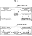
- FIG 17 is a schematic block diagram to show an image forming system of the invention.
- the image forming system comprises an image forming apparatus 1 and an external machine 10.
- the image forming apparatus 1 is provided with a first I/F section 2, a data conversion section 3, a first storage section 4, a printing section 5, a control section 6, and an identification code assignment section 7.
- the external machine 10 is provided with a second I/F section 11, a second storage section 12, a display section 13, an input section 14, and a control section 15.
- the first I/F section 2 is a section being connected to the external machine 10 via a cable or in a wireless manner for receiving image data to be printed from the external machine 10 and transmitting and receiving data of identification codes, etc.
- the data conversion section 3 is a section for converting the image data received at the first I/F section 2 into data that can be printed in the printing section 5.
- the identification code assignment section 7 is a section for assigning an identification code in relation with a print image for each page unit or print job unit (namely, file unit).
- the information contained in the identification code may be the serial number of a printer, the serial number of the document, a password, etc. These information pieces may be assigned in characters, digits, or symbols or a combination thereof, etc.
- the first storage section 4 is a section for storing programs required for controlling the entire image forming apparatus 1, font, etc., required for the data conversion section 3, print images printed in the printing section 5, and identification codes corresponding to the print images, assigned by the identification code assignment section 7.
- the printing section 5 is a section for printing the data provided by the data conversion section 3 on a recording medium.
- the control section 6 is a section for controlling the entire image forming apparatus 1.
- the second I/F section 11 is a section being connected to the first I/F section 2 via a cable or in a wireless manner for transmitting image data to the image forming apparatus 1 and transmitting and receiving data of identification codes, etc.
- the second storage section 12 is a section for storing programs required for controlling the entire external machine 10 and data of identification codes, etc., received on the second I/F section 12.
- the display section 13 is a section for displaying characters, digits, or symbols or a combination thereof, etc.,; it can display identification codes.
- the input section 14, which is made of a normal keyboard, is also a section enabling the user to prepare an image and select one of the identification codes displayed on the display section 13.
- a print image and its corresponding identification code are stored in the first storage section 4 and at the same time, the identification code is stored in the second storage section 12.
- the identification codes are displayed on the display section 13 and the identification code of the print image to be printed is selected through the selection section 14, whereby the print image can be taken out from the first storage section 4 via the second I/F section 11 and the first I/F section 2; it can be printed any number of times.
- related information to the print image corresponding to an identification code together with the identification code is transferred between a first I/F section 2 and a second I/F section 11 and is stored in a second storage section 12, then the identification code and the related information may be displayed on a display section 13.
- rough information on the print image corresponding to the identification code can be known without seeing the recording medium and the time to printing can be reduced drastically.
- FIG. 18 is a schematic block diagram to show an image forming system of the invention.
- the image forming system comprises an image forming apparatus 1 and an external machine 11.
- the image forming apparatus 1 is provided with an I/F section 2, a data conversion section 3, a storage section 4, a printing section 5, a control section 6, an identification code assignment section 7, and a card insertion section 8.
- the external machine 11 is provided with an I/F section 12, a display section 13, a selection section 14, a control section 16, and a card insertion section 18.
- the I/F section 2 is a section being connected to the external machine 11 via a cable or in a wireless manner for receiving image data to be printed from the external machine 11 and receiving data of identification codes, etc.
- the data conversion section 3 is a section for converting the image data received at the I/F section 2 into data that can be printed in the printing section 5.
- the identification code assignment section 7 is a section for assigning an identification code in relation with a print image for each page unit or print job unit (namely, file unit).
- the information contained in the identification code may be the serial number of a printer, the serial number of the document, a password, etc. These information pieces may be assigned in characters, digits, or symbols or a combination thereof, etc.
- the storage section 4 is a section for storing programs required for controlling the entire image forming apparatus 1, font, etc., required for the data conversion section 3, print images printed in the printing section 5, and identification codes corresponding to the print images, assigned by the identification code assignment section 7.
- the printing section 5 is a section for printing the data provided by the data conversion section 3 on a recording medium.
- the control section 6 is a section for controlling the entire image forming apparatus 1.
- the card insertion section 8 is a slot into which a readable/writable card can be inserted; when a card is inserted into the card insertion section 8, the identification code assigned by the identification code assignment section 7 is written onto the card as data. The written identification codes may be stored until the card fills with data.
- the I/F section 12 is a section being connected to the I/F section 2 via a cable or in a wireless manner for transmitting image data to the image forming apparatus 1 and transmitting identification codes.
- the display section 13 is a section for displaying characters, digits, or symbols or a combination thereof, etc.,; it can display identification codes.
- the selection section 14 which is made of a normal keyboard, is a section enabling the user to prepare an image and moreover select one of the identification codes displayed on the display section 13.
- the control section 16 is a section for controlling the entire external machine 11.
- the card insertion section 18 is a slot into which a card can be inserted; when a card inserted into the card insertion section 8 and having an identification code written is inserted into the card insertion section 18, the identification code written on the card is read and is displayed on the display section 13.
- a print image and its corresponding identification code are stored in the storage section 4 and at the same time, the identification code is written onto the card inserted into the card insertion section 8.
- the identification codes written on the card are displayed on the display section 13, and the identification code of the print image to be printed is selected through the selection section 14, whereby the print image corresponding to the identification code can be taken out from the storage section 4 via the I/F sections 12 and 2; it can be printed any number of times.
- an identification code is not printed on recording paper and is written onto a card.
- its corresponding identification code may be printed with the print image. In doing so, if the recording paper is seen, which image data the identification code corresponds to is known; when the identification code is selected on the selection section 14, the selection time can be reduced drastically.
- an identification code is written onto the card inserted into a card insertion section 8
- related information to the print image corresponding to the identification code such as a title, the document number, the document name, the data creation date, the creator (user name), or the file name of an external machine like a personal computer
- the identification code and its relevant information may be displayed together on a display section 13.
- rough information on the print image corresponding to the identification code can be known without seeing the recording medium and when the identification code is selected on a selection section 14, the time can be reduced drastically.
- FIG 19 is a schematic block diagram to show an image forming apparatus of the invention.
- An image forming apparatus 1 comprises an I/F section 2, a data conversion section 3, a storage section 4, a printing section 5, a control section 6, and an identification code assignment section 7.
- the I/F section 2 is a section being connected to a network bus line for receiving image data to be printed from an information processing unit and identification code data from a terminal adapter unit.
- the data conversion section 3 is a section for converting the image data received at the I/F section 2 into data that can be printed in the printing section 5.
- the identification code assignment section 7 is a section for assigning an identification code in relation with a print image for each page unit or print job unit (namely, file unit).
- the information contained in the identification code may be the serial number of a printer, the serial number of the document, a password, etc. These information pieces may be assigned in characters, digits, or symbols or a combination thereof, etc.
- the storage section 4 is a section for storing programs required for controlling the entire image forming apparatus 1, font, etc., required for the data conversion section 3, print images printed in the printing section 5, and identification codes corresponding to the print images, assigned by the identification code assignment section 7.
- the printing section 5 is a section for printing the print image provided by the data conversion section 3 and the identification code corresponding to the print image on a recording medium.
- the control section 6 is a section for controlling the entire image forming apparatus 1.
- FIG 20 is a schematic block diagram to show an image forming system of the invention.
- the image forming system comprises a plurality of information processing units 12, a plurality of image forming apparatus 1, and a terminal adapter unit 13 connected by a bus line 11.
- each image forming apparatus 1 stores a print image and its corresponding identification code in a storage section 4 and at the same time, prints the identification code on a recording medium in a printing section 5.
- the identification code printed on the recording medium is simply transmitted from an external machine to the terminal adapter unit 13, whereby the print image corresponding to the identification code can be taken out from the storage section 4 via an I/F section 2 and can be printed any number of times.
- the external machine may be a machine which enables the user to enter characters, digits, or symbols as an identification code and can be connected to a telephone line or can communicate with a base station; for example, an information processing machine such as a personal computer, a telephone, a portable telephone, or a portable terminal may be used.
- the terminal adapter unit 13 executes wireless reception, the external machine may be a machine which enables the user to enter characters, digits, or symbols as an identification code and can execute wireless transmission; for example, a radio cordless telephone may be used.
- the image forming apparatus having the storage section 4 may print the print image; the taken-out print image may be transmitted to another image forming apparatus over the bus line 11 for printing the print image at this image forming apparatus.
- a print end message is transmitted from the terminal adapter unit 13 to the external machine, the user of the external machine can check whether or not the printing is complete although he or she does not exist in the vicinity of the image forming apparatus.
- Printed identification code is transmitted together with the print end message and is stored in the external machine, whereby it can be used for specification when the same print image is again printed; good use of a reception history can be made for an electronic filing system.
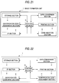
- FIG 21 is a schematic block diagram to show an image forming apparatus of the invention.
- An image forming apparatus 1 comprises an I/F section 2, a data conversion section 3, a storage section 4, a printing section 5, a control section 6, an identification code assignment section 7, and a card insertion section 8.
- the I/F section 2 is a section being connected to a network bus line for receiving image data to be printed from an information processing unit and identification code data from a terminal adapter unit.
- the data conversion section 3 is a section for converting the image data received at the I/F section 2 into data that can be printed in the printing section 5.
- the identification code assignment section 7 is a section for assigning an identification code in relation with a print image for each page unit or print job unit (namely, file unit).
- the information contained in the identification code may be the serial number of a printer, the serial number of the document, a password, etc. These information pieces may be assigned in characters, digits, or symbols or a combination thereof, etc.
- the storage section 4 is a section for storing programs required for controlling the entire image forming apparatus 1, font, etc., required for the data conversion section 3, print images printed in the printing section 5, and identification codes corresponding to the print images, assigned by the identification code assignment section 7.
- the printing section 5 is a section for printing the print image provided by the data conversion section 3 and the identification code corresponding to the print image on a recording medium.
- the control section 6 is a section for controlling the entire image forming apparatus 1.
- the card insertion section 8 is a slot into which a readable/writable card can be inserted; when a card is inserted into the card insertion section 8, the identification code assigned by the identification code assignment section 7 is written onto the card as data. The written identification codes may be stored until the card fills with data.
- the image forming system comprises a plurality of information processing units 12, a plurality of image forming apparatus 1, and a terminal adapter unit 13 connected by a bus line 11 as shown in Figure 20.
- each image forming apparatus 1 stores a print image and its corresponding identification code in a storage section 4 and at the same time, writes the identification code onto a card inserted into a card insertion section 8.
- the user inserts the card into an external machine for read, selects any desired identification code, and transmits the selected identification code to a terminal adapter unit 13, whereby the print image corresponding to the identification code can be taken out from the storage section 4 via an I/F section 2 and can be printed any number of times.
- the external machine may be a machine which enables insertion of a card and can be connected to a telephone line or can communicate with a base station; for example, an information processing machine such as a personal computer, a telephone, a portable telephone, or a portable terminal may be used.
- the terminal adapter unit 13 executes wireless reception, the external machine may be a machine which enables insertion of a card and can execute wireless transmission; for example, a radio cordless telephone may be used.
- the external machine may be integral with a card; time and effort for inserting the card into the external machine after the card is inserted into a main unit 1 can be saved.
- the image forming apparatus having the storage section 4 may print the print image; the taken-out print image may be transmitted to another image forming apparatus over the bus line 11 for printing the print image at this image forming apparatus.
- an identification code is not printed on recording paper and is written onto a card.
- its corresponding identification code may be printed with the print image. In doing so, if the recording paper is seen, which image data the identification code corresponds to is known; when the identification code is selected on the external machine, the selection time can be reduced drastically.
- an identification code is written onto the card inserted into the card insertion section 8
- related information to the print image corresponding to the identification code such as a title, the document number, the document name, the data creation date, the creator (user name), or the file name of an external machine like a personal computer, may be written onto the card.
- the identification code and its relevant information can be known together and when the identification code is selected on the external machine, the selection time can be reduced drastically.
- a print end message is transmitted from the terminal adapter unit 13 to the external machine, the user of the external machine can check whether or not the printing is complete although he or she does not exist in the vicinity of the image forming apparatus.
- Printed identification code is transmitted together with the print end message and is stored in the external machine, whereby it can be used for specification when the same print image is again printed; good use of a reception history can be made for an electronic filing system.
- FIG 22 is a schematic block diagram to show an image forming apparatus according to the invention.
- An image forming apparatus 1 comprises an I/F section 2, a data conversion section 3, a storage-section 4, a printing section 5, a control section 6, an identification code assignment section 7, and an identification code input section 8.
- the I/F section 2 is a section being connected to a computer, etc., via a cable for receiving image data to be printed from the computer, etc.
- the data conversion section 3 is a section for converting the image data received at the I/F section 2 into data that can be printed in the printing section 5.
- the identification code assignment section 7 is a section for assigning an identification code in relation with a print image for each page unit or print job unit (namely, file unit).
- the information contained in the identification code may be the serial number of a printer, the serial number of the document, a password, etc. These information pieces may be assigned in characters, digits, etc.
- the storage section 4 is a section for storing programs required for controlling the entire image forming apparatus 1, font, etc., required for the data conversion section 3, print images printed in the printing section 5, and identification codes in a one-to-one correspondence with print images for each page unit or print job unit, assigned by the identification code assignment section 7.
- the printing section 5 is a section for printing the data provided by the data conversion section 3 and the identification code assigned by the identification code assignment section 7 on a recording medium at the same time.
- the control section 6 is a section for controlling the entire image forming apparatus 1.
- the identification code input section 8 is a section for entering the identification code printed on a recording medium; keys attached to the image forming apparatus 1 or ten keys connected to the image forming apparatus 1 in a wireless or wire manner may be used as the identification code input section 8.
- a print image and an identification code are printed on a recording medium and at the same time, are stored in the storage section 4.
- the identification code printed on the recording medium is simply entered through the identification code input section 8, whereby the print image can be taken out from the storage section 4 and can be printed any number of times.
- the identification code may be printed as follows: (Which print method is adopted may be previously specified or the image forming apparatus may be provided with selection means for selecting any one of the print methods or a combination thereof.)
- every recording medium of print can be read through the identification code input section 8.
- the image forming apparatus of the invention is provided with network control means capable of also accessing other external machines and read and output means capable of reading and outputting print images of other units, documents of other image forming apparatus can also be drawn out and print images can be shared because the serial number of each image forming apparatus is contained in the identification code. If the correspondence between the alphanumeric strings as the serial numbers and the image forming apparatus is indicated, which image forming apparatus the document is printed at is known and if the identification code is entered through the identification code input section 8 of the image forming apparatus, the document can be printed promptly.
- the image forming apparatus is connected to a host, etc., and is provided with means that can respond to retrieval, read, and output instructions from the host, etc., the host can manage files and list the stored print image contents.
- the image forming apparatus is provided with means that can respond to setting of copy protect from the host, etc., the security of print images can be maintained.
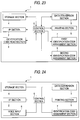
- FIG. 23 is a schematic block diagram to show an image forming apparatus according to the invention.
- An image forming apparatus 1 comprises an I/F section 2, a data conversion section 3, a storage section 4, a printing section 5, a control section 6, a first identification code assignment section 7, an identification code read section 8, and a second identification code assignment section 9.
- the I/F section 2 is a section being connected to a computer, etc., via a cable for receiving image data to be printed from the computer, etc.
- the data conversion section 3 is a section for converting the image data received at the I/F section 2 into data that can be printed in the printing section 5.
- the first identification code assignment section 7 is a section for assigning an identification code in relation with a print image for each page unit or print job unit (namely, file unit).
- the information contained in the identification code may be the serial number of a printer, the serial number of the document, a password, etc. These information pieces may be compressed and encrypted.
- the storage section 4 is a section for storing programs required for controlling the entire image forming apparatus 1, font, etc., required for the data conversion section 3, print images printed in the printing section 5, and identification codes in a one-to-one correspondence with print images assigned by the first identification code assignment section 7.
- the printing section 5 is a section for printing the data provided by the data conversion section 3 on a recording medium.
- the second identification code assignment section 9 is a section for assigning an identification code to a recording medium when the printing section 5 prints.
- the identification code may be assigned in paint emitting infrared rays or transparent magnetic toner; only print images may be printed on the recording medium.
- the control section 6 is a section for controlling the entire image forming apparatus 1.
- the identification code read section 8 is a section for reading the identification code assigned to a recording medium; for example, if the second identification code assignment section 9 assigns an identification code in paint emitting infrared rays, the identification code read section 8 may be made of an infrared sensor or if the second identification code assignment section 9 assigns an identification code in magnetic toner, the identification code read section 8 may be made of a magnetic reader.
- a print image is printed on a recording medium and an identification code is assigned and at the same time, they are stored in the storage section 4.
- the identification code assigned to the recording medium is simply read through the identification code read section 8, whereby the print image can be taken out from the storage section 4 and can be printed any-number of times.
- the identification code can be assigned to the recording medium transparently.
- the identification code may be assigned as follows: (Which method is adopted may be previously specified or the image forming apparatus may be provided with selection means for selecting any one of the print methods or a combination thereof.)
- every recording medium of print can be read through the identification code read section 8.
- the image forming apparatus of the invention is provided with network control means capable of also accessing other external machines and read and output means capable of reading and outputting print images of other units, documents of other image forming apparatus can also be drawn out and print images can be shared because the serial number of each image forming apparatus is contained in the identification code.
- the image forming apparatus is connected to a host, etc., and is provided with means that can respond to retrieval, read, and output instructions from the host, etc., the host can manage files and list the stored print image contents.
- the image forming apparatus is provided with means that can respond to setting of copy protect from the host, etc., the security of print images can be maintained.
- FIG 24 is a schematic block diagram to show an image forming apparatus according to the invention.
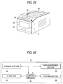
- An image forming apparatus 1 comprises an I/F section 2, a data conversion section 3, a storage section 4, a printing section 5, a control section 6, an identification code assignment section 7, and a voice input section 8.
- the I/F section 2 is a section being connected to a computer, etc., via a cable for receiving image data to be printed from the computer, etc.
- the data conversion section 3 is a section for converting the image data received at the I/F section 2 into data that can be printed in the printing section 5.
- the identification code assignment section 7 is a section for assigning an identification code in relation with a print image for each page unit or print job unit (namely, file unit).
- the information contained in the identification code may be the serial number of a printer, the serial number of the document, a password, etc. These information pieces may be assigned in characters, digits, etc.
- the storage section 4 is a section for storing programs required for controlling the entire image forming apparatus 1, font, etc., required for the data conversion section 3, print images printed in the printing section 5, and identification codes in a one-to-one correspondence with print images assigned by the first identification code assignment section 7.
- the printing section 5 is a section for printing the data provided by the data conversion section 3 and the identification code assigned by the identification code assignment section 7 on a recording medium at the same time.
- the control section 6 is a section for controlling the entire image forming apparatus 1.
- the voice input section 8 is a section for entering an identification code in voice by the user of the image forming apparatus 1 and converting input voice into identification code data of characters, digits, etc.
- a print image and an identification code are printed on a recording medium and at the same time, are stored in the storage section 4.
- the identification code printed on the recording medium is simply entered in voice through the voice input section 8, whereby the print image can be taken out from the storage section 4 and can be printed any number of times.
- the identification code may be assigned as follows: (Which print method is adopted may be previously specified or the image forming apparatus may be provided with selection means for selecting any one of the print methods or a combination thereof.)
- every recording medium of print can be read through the identification code input section 8.
- FIG. 25 is a schematic perspective view to show the image forming apparatus according to the invention.
- the image forming apparatus has an operation panel 21, a display section 22, a tray 23 as a cassette paper feed section, a cassette 24, and a recording medium discharge section 25. Further, it comprises the voice input section 8 on the front.
- the image forming apparatus of the invention is provided with network control means capable of also accessing other external machines and read and output means capable of reading and outputting print images of other units, documents of other image forming apparatus can also be drawn out and print images can be shared because the serial number of each image forming apparatus is contained in the identification code.
- the print image corresponding to the identification code can be printed on the image forming apparatus.
- the document can be printed promptly.
- the image forming apparatus is connected to a host, etc., and is provided with means that can respond to retrieval, read, and output instructions from the host, etc., the host can manage files and list the stored print image contents.
- the image forming apparatus is provided with means that can respond to setting of copy protect from the host, etc., the security of print images can be maintained.
- the image forming apparatus can print any number of times with the same resolution and moreover in a short time; particularly if it is adopted for a color printer, an efficient image forming apparatus and image forming system can be provided.
Landscapes
- Engineering & Computer Science (AREA)
- Physics & Mathematics (AREA)
- General Physics & Mathematics (AREA)
- Theoretical Computer Science (AREA)
- General Engineering & Computer Science (AREA)
- Record Information Processing For Printing (AREA)
- Accessory Devices And Overall Control Thereof (AREA)
Applications Claiming Priority (24)
| Application Number | Priority Date | Filing Date | Title |
|---|---|---|---|
| JP258116/96 | 1996-09-30 | ||
| JP25811696 | 1996-09-30 | ||
| JP9140142A JPH10151823A (ja) | 1996-09-30 | 1997-05-29 | 画像形成装置 |
| JP140140/97 | 1997-05-29 | ||
| JP14014197A JP4084441B2 (ja) | 1996-09-30 | 1997-05-29 | 画像形成装置 |
| JP14014097A JP3404255B2 (ja) | 1996-09-30 | 1997-05-29 | 画像形成装置 |
| JP140142/97 | 1997-05-29 | ||
| JP140141/97 | 1997-05-29 | ||
| JP5296/97U | 1997-06-05 | ||
| JP1997005296U JP3045248U (ja) | 1996-09-30 | 1997-06-05 | 画像形成装置 |
| JP147922/97 | 1997-06-05 | ||
| JP9147922A JPH10151824A (ja) | 1996-09-30 | 1997-06-05 | 画像形成装置 |
| JP14880197A JP4084442B2 (ja) | 1996-09-30 | 1997-06-06 | 画像形成システム |
| JP148801/97 | 1997-06-06 | ||
| JP14880097A JP3404256B2 (ja) | 1996-09-30 | 1997-06-06 | 画像形成装置 |
| JP148800/97 | 1997-06-06 | ||
| JP9205043A JPH10154046A (ja) | 1996-09-30 | 1997-07-30 | 画像形成システム |
| JP205043/97 | 1997-07-30 | ||
| JP205042/97 | 1997-07-30 | ||
| JP9205044A JPH10151829A (ja) | 1996-09-30 | 1997-07-30 | 画像形成システム |
| JP205041/97 | 1997-07-30 | ||
| JP9205041A JPH10151827A (ja) | 1996-09-30 | 1997-07-30 | 画像形成システム |
| JP9205042A JPH10151828A (ja) | 1996-09-30 | 1997-07-30 | 画像形成装置 |
| JP205044/97 | 1997-07-30 |
Publications (3)
| Publication Number | Publication Date |
|---|---|
| EP0833276A2 true EP0833276A2 (fr) | 1998-04-01 |
| EP0833276A3 EP0833276A3 (fr) | 1998-12-16 |
| EP0833276B1 EP0833276B1 (fr) | 2006-06-07 |
Family
ID=27583128
Family Applications (1)
| Application Number | Title | Priority Date | Filing Date |
|---|---|---|---|
| EP97116989A Expired - Lifetime EP0833276B1 (fr) | 1996-09-30 | 1997-09-30 | Système et appareil de formation d'images |
Country Status (2)
| Country | Link |
|---|---|
| US (1) | US6137590A (fr) |
| EP (1) | EP0833276B1 (fr) |
Cited By (5)
| Publication number | Priority date | Publication date | Assignee | Title |
|---|---|---|---|---|
| EP1058201A1 (fr) * | 1999-05-31 | 2000-12-06 | Sibocar S.r.l. | Méthode et dispostif d'impression de marques codées sur des plaquettes d'identification de câbles et de composants électriques |
| EP1343634A4 (fr) * | 2000-11-27 | 2006-06-21 | Silverbrook Res Pty Ltd | Imprimante a commande de classement manuelle |
| US7414741B2 (en) | 2000-11-25 | 2008-08-19 | Silverbrook Research Pty Ltd | Printer with manual collation control |
| SG144717A1 (en) * | 1999-10-25 | 2008-08-28 | Silverbrook Res Pty Ltd | Copier |
| SG153643A1 (en) * | 2000-11-27 | 2009-07-29 | Silverbrook Res Pty Ltd | Printer with network interface |
Families Citing this family (24)
| Publication number | Priority date | Publication date | Assignee | Title |
|---|---|---|---|---|
| JP2000108468A (ja) * | 1998-10-07 | 2000-04-18 | Fuji Photo Film Co Ltd | プリンター |
| US6987573B1 (en) * | 1999-05-25 | 2006-01-17 | Silverbrook Research Pty Ltd | Interface surface printer |
| AUPQ439299A0 (en) * | 1999-12-01 | 1999-12-23 | Silverbrook Research Pty Ltd | Interface system |
| US6980318B1 (en) * | 1999-05-25 | 2005-12-27 | Silverbrook Research Pty Ltd | Method and system for delivery of a greeting card |
| US7999964B2 (en) | 1999-12-01 | 2011-08-16 | Silverbrook Research Pty Ltd | Printing on pre-tagged media |
| JP4204744B2 (ja) * | 2000-07-05 | 2009-01-07 | 富士フイルム株式会社 | 画像分類システム |
| USD451102S1 (en) | 2000-07-24 | 2001-11-27 | Wu-Lang Huang | Image converter |
| GB0018972D0 (en) * | 2000-08-02 | 2000-09-20 | Rue De Int Ltd | Document handling system |
| JP3877944B2 (ja) | 2000-08-03 | 2007-02-07 | シャープ株式会社 | 画像出力装置制御システム |
| US7099026B1 (en) * | 2000-10-17 | 2006-08-29 | International Business Machines Corporation | Unique printer pass code system and method |
| US7515292B2 (en) * | 2000-11-25 | 2009-04-07 | Silverbrook Research Pty Ltd | Apparatus for cooling and storing produce |
| US20030063772A1 (en) * | 2001-09-06 | 2003-04-03 | Smith Joshua R. | System and method for authentication and tracking of a workpiece that includes an optically active medium |
| JP4212797B2 (ja) * | 2001-10-12 | 2009-01-21 | 株式会社リコー | セキュリティシステム及びセキュリティ管理方法 |
| US20040205662A1 (en) * | 2002-05-30 | 2004-10-14 | Brad Anderson | Image preservation and reconstruction |
| JP2004009454A (ja) * | 2002-06-05 | 2004-01-15 | Fuji Photo Film Co Ltd | プリンタ及びプリント方法 |
| JP2004046537A (ja) * | 2002-07-11 | 2004-02-12 | Canon Inc | 画像処理装置及びその処理方法 |
| US20050134897A1 (en) * | 2003-03-21 | 2005-06-23 | Toshiba Tec Kabushiki Kaisha | Image forming apparatus |
| US6885910B2 (en) * | 2003-09-02 | 2005-04-26 | Pitney Bowes Inc. | Mail inserter machine remote control with a scanner |
| JP4150923B2 (ja) * | 2003-12-09 | 2008-09-17 | 富士ゼロックス株式会社 | データ出力システムおよびその方法 |
| US20070171460A1 (en) * | 2006-01-24 | 2007-07-26 | Lexmark International, Inc. | Photo duplexing method |
| JP4836260B2 (ja) * | 2006-12-05 | 2011-12-14 | キヤノン株式会社 | 画像形成装置、画像形成方法、記録媒体及びプログラム |
| JP2009118327A (ja) * | 2007-11-08 | 2009-05-28 | Fuji Xerox Co Ltd | 画像形成装置、プログラム、および媒体 |
| JP5304687B2 (ja) * | 2010-02-26 | 2013-10-02 | ブラザー工業株式会社 | 印刷装置、印刷方法、プログラム及び印刷システム |
| JP7251194B2 (ja) * | 2019-02-15 | 2023-04-04 | セイコーエプソン株式会社 | 印刷システム、印刷方法、情報処理装置、及び、情報処理プログラム |
Family Cites Families (26)
| Publication number | Priority date | Publication date | Assignee | Title |
|---|---|---|---|---|
| DE258488C (fr) * | ||||
| JPS5515122A (en) * | 1978-07-18 | 1980-02-02 | Toshiba Corp | Electronic printer |
| US4408181A (en) * | 1979-04-10 | 1983-10-04 | Tokyo Shibaura Denki Kabushiki Kaisha | Document data filing/retrieval system |
| US4455039A (en) * | 1979-10-16 | 1984-06-19 | Coulter Systems Corporation | Encoded security document |
| JPS59121070A (ja) * | 1982-12-28 | 1984-07-12 | Ricoh Co Ltd | 複写装置 |
| ATE63008T1 (de) * | 1986-09-05 | 1991-05-15 | Staude Foto Chemie Eva | Vorrichtung und verfahren zur verfilmung von dokumenten. |
| US4829166A (en) * | 1986-12-01 | 1989-05-09 | Froelich Ronald W | Computerized data-bearing card and reader/writer therefor |
| JPH03162979A (ja) * | 1989-11-21 | 1991-07-12 | Nec Data Terminal Ltd | プリンタ装置 |
| GB9020010D0 (en) * | 1990-09-13 | 1990-10-24 | Marshall Ieuan J M | Improvements relating to buffer storage devices |
| JPH04146458A (ja) * | 1990-10-08 | 1992-05-20 | Matsushita Electric Ind Co Ltd | バーコードデータ印刷機能付複写機 |
| JPH04205225A (ja) * | 1990-11-30 | 1992-07-27 | Canon Inc | 印刷システム |
| JPH0644320A (ja) * | 1991-05-14 | 1994-02-18 | Sony Corp | 情報検索システム |
| US5978552A (en) * | 1991-11-28 | 1999-11-02 | Sony Corporation | Ruled line generating apparatus and sheet for use therein |
| US5822083A (en) * | 1992-10-02 | 1998-10-13 | Canon Kabushiki Kaisha | Image storing apparatus |
| US5243381A (en) * | 1993-01-04 | 1993-09-07 | Xerox Corporation | Method for compiling multiple jobs with job reference sheets |
| US5316279A (en) * | 1993-01-04 | 1994-05-31 | Xerox Corporation | Copier/printer job stacking with discrete cover sheets with extending printed banners |
| JP3689127B2 (ja) * | 1993-04-22 | 2005-08-31 | ゼロックス コーポレイション | 文書処理システムと文書処理方法 |
| CA2122098C (fr) * | 1993-04-27 | 1999-02-02 | Michael John Camille Marsh | Appareil d'impression |
| JP3043541B2 (ja) * | 1993-06-23 | 2000-05-22 | キヤノン株式会社 | 像形成装置,像形成システムおよびその像形成方法 |
| DE4332561A1 (de) * | 1993-09-24 | 1995-03-30 | Esselte Meto Int Gmbh | Druckmaschine mit einem Bedienungspanel |
| JPH07244657A (ja) * | 1994-03-02 | 1995-09-19 | Matsushita Electric Ind Co Ltd | 文書編集装置 |
| US5553312A (en) * | 1994-06-20 | 1996-09-03 | Acs Wireless, Inc. | Data transfer and communication network |
| US5561528A (en) * | 1994-08-03 | 1996-10-01 | Lexmark International, Inc. | Forms on demand printing |
| DE69629071T2 (de) * | 1995-03-29 | 2004-04-22 | Eastman Kodak Co. | Vorrichtung zum Drucken, Speichern und Wiederauffinden eines aufgezeichneten Bildes |
| US5699493A (en) * | 1995-06-23 | 1997-12-16 | Lexmark International, Inc. | Method and apparatus for providing job accounting information to a host computer from a printer |
| US5754308A (en) * | 1995-06-27 | 1998-05-19 | Panasonic Technologies, Inc. | System and method for archiving digital versions of documents and for generating quality printed documents therefrom |
-
1997
- 1997-09-26 US US08/938,768 patent/US6137590A/en not_active Expired - Fee Related
- 1997-09-30 EP EP97116989A patent/EP0833276B1/fr not_active Expired - Lifetime
Cited By (10)
| Publication number | Priority date | Publication date | Assignee | Title |
|---|---|---|---|---|
| EP1058201A1 (fr) * | 1999-05-31 | 2000-12-06 | Sibocar S.r.l. | Méthode et dispostif d'impression de marques codées sur des plaquettes d'identification de câbles et de composants électriques |
| SG144717A1 (en) * | 1999-10-25 | 2008-08-28 | Silverbrook Res Pty Ltd | Copier |
| US7557944B2 (en) | 1999-10-25 | 2009-07-07 | Silverbrook Research Pty Ltd | Copier |
| US7986427B2 (en) | 1999-10-25 | 2011-07-26 | Silverbrook Research Pty Ltd | System for copying interactive documents |
| US7414741B2 (en) | 2000-11-25 | 2008-08-19 | Silverbrook Research Pty Ltd | Printer with manual collation control |
| US7557948B2 (en) | 2000-11-25 | 2009-07-07 | Silverbrook Research Pty Ltd | Document copier with a controller for decoding optical patterns on sheets of media |
| US7773247B2 (en) | 2000-11-25 | 2010-08-10 | Silverbrook Research Pty Ltd | Document copier printing a copy of an input sheet by retrieving an electronic document associated with the input sheet |
| US8018605B2 (en) | 2000-11-25 | 2011-09-13 | Silverbrook Research Pty Ltd | Document copier printing a copy of an input sheet by retrieving an electronic document containing content of the input sheet |
| EP1343634A4 (fr) * | 2000-11-27 | 2006-06-21 | Silverbrook Res Pty Ltd | Imprimante a commande de classement manuelle |
| SG153643A1 (en) * | 2000-11-27 | 2009-07-29 | Silverbrook Res Pty Ltd | Printer with network interface |
Also Published As
| Publication number | Publication date |
|---|---|
| EP0833276A3 (fr) | 1998-12-16 |
| US6137590A (en) | 2000-10-24 |
| EP0833276B1 (fr) | 2006-06-07 |
Similar Documents
| Publication | Publication Date | Title |
|---|---|---|
| EP0833276A2 (fr) | Système et appareil de formation d'images | |
| EP0025683B1 (fr) | Système de transmission en fac-similé | |
| EP0689157B1 (fr) | Appareil pour imprimer des données numériques d'image | |
| US5974202A (en) | Apparatus and method for processing a machine readable document with embedded machine instructions | |
| CA1208797A (fr) | Systeme de traitement et d'extraction de donnees | |
| EP0605717B2 (fr) | Systeme de balayage a demarrage automatique | |
| US5506697A (en) | Apparatus for processing human-readable and machine-readable documents | |
| US6002491A (en) | Apparatus for processing human-readable and machine-readable documents | |
| US6823092B1 (en) | Image data registering apparatus and method, storage medium, and program product | |
| EP1126404B1 (fr) | Scanner d'image et dispositif de reconnaissance optique de caracteres mettant en oeuvre ledit scanner | |
| US20080239360A1 (en) | Quick edit and speed print capability for a stand-alone ink jet printer | |
| EP0461920B1 (fr) | Systèmes d'imprimerie | |
| EP0539135A2 (fr) | Méthode et dispositif pour imprimer | |
| US6669085B1 (en) | Making language localization and telecommunications settings in a multi-function device through image scanning | |
| US5988898A (en) | Label printer having integrated optical scanner module | |
| US7345784B2 (en) | Image forming apparatus and image forming method | |
| US7326920B2 (en) | Multi function peripheral having radio reader and writer for communicating with IC chips | |
| CA2048794A1 (fr) | Procede de fusion en impression electronique | |
| EP0545708A1 (fr) | Procédé de transmission d'image et son appareil | |
| US7385715B2 (en) | Quick edit and speed print capability for a stand-alone ink jet printer | |
| JP3404256B2 (ja) | 画像形成装置 | |
| US20240265716A1 (en) | Image processing apparatus and label printing system | |
| JP3404255B2 (ja) | 画像形成装置 | |
| JP4835213B2 (ja) | 印刷システム | |
| KR100552794B1 (ko) | 수동식 페이지정리 제어기를 구비한 프린터 |
Legal Events
| Date | Code | Title | Description |
|---|---|---|---|
| PUAI | Public reference made under article 153(3) epc to a published international application that has entered the european phase |
Free format text: ORIGINAL CODE: 0009012 |
|
| AK | Designated contracting states |
Kind code of ref document: A2 Designated state(s): DE FR GB |
|
| PUAL | Search report despatched |
Free format text: ORIGINAL CODE: 0009013 |
|
| AK | Designated contracting states |
Kind code of ref document: A3 Designated state(s): AT BE CH DE DK ES FI FR GB GR IE IT LI LU MC NL PT SE |
|
| 17P | Request for examination filed |
Effective date: 19990409 |
|
| AKX | Designation fees paid |
Free format text: DE FR GB |
|
| 17Q | First examination report despatched |
Effective date: 20021112 |
|
| GRAP | Despatch of communication of intention to grant a patent |
Free format text: ORIGINAL CODE: EPIDOSNIGR1 |
|
| GRAS | Grant fee paid |
Free format text: ORIGINAL CODE: EPIDOSNIGR3 |
|
| GRAA | (expected) grant |
Free format text: ORIGINAL CODE: 0009210 |
|
| AK | Designated contracting states |
Kind code of ref document: B1 Designated state(s): DE FR GB |
|
| REG | Reference to a national code |
Ref country code: GB Ref legal event code: FG4D |
|
| REF | Corresponds to: |
Ref document number: 69736041 Country of ref document: DE Date of ref document: 20060720 Kind code of ref document: P |
|
| ET | Fr: translation filed | ||
| PLBE | No opposition filed within time limit |
Free format text: ORIGINAL CODE: 0009261 |
|
| STAA | Information on the status of an ep patent application or granted ep patent |
Free format text: STATUS: NO OPPOSITION FILED WITHIN TIME LIMIT |
|
| 26N | No opposition filed |
Effective date: 20070308 |
|
| PGFP | Annual fee paid to national office [announced via postgrant information from national office to epo] |
Ref country code: FR Payment date: 20080915 Year of fee payment: 12 |
|
| PGFP | Annual fee paid to national office [announced via postgrant information from national office to epo] |
Ref country code: DE Payment date: 20081014 Year of fee payment: 12 |
|
| PGFP | Annual fee paid to national office [announced via postgrant information from national office to epo] |
Ref country code: GB Payment date: 20081001 Year of fee payment: 12 |
|
| GBPC | Gb: european patent ceased through non-payment of renewal fee |
Effective date: 20090930 |
|
| REG | Reference to a national code |
Ref country code: FR Ref legal event code: ST Effective date: 20100531 |
|
| PG25 | Lapsed in a contracting state [announced via postgrant information from national office to epo] |
Ref country code: FR Free format text: LAPSE BECAUSE OF NON-PAYMENT OF DUE FEES Effective date: 20090930 Ref country code: DE Free format text: LAPSE BECAUSE OF NON-PAYMENT OF DUE FEES Effective date: 20100401 |
|
| PG25 | Lapsed in a contracting state [announced via postgrant information from national office to epo] |
Ref country code: GB Free format text: LAPSE BECAUSE OF NON-PAYMENT OF DUE FEES Effective date: 20090930 |