EP0833288A2 - Procédé pour la transmission radioélectrique de données des capteurs et système d'alarme radio - Google Patents
Procédé pour la transmission radioélectrique de données des capteurs et système d'alarme radio Download PDFInfo
- Publication number
- EP0833288A2 EP0833288A2 EP97116269A EP97116269A EP0833288A2 EP 0833288 A2 EP0833288 A2 EP 0833288A2 EP 97116269 A EP97116269 A EP 97116269A EP 97116269 A EP97116269 A EP 97116269A EP 0833288 A2 EP0833288 A2 EP 0833288A2
- Authority
- EP
- European Patent Office
- Prior art keywords
- sensors
- radio
- sensor
- transmission
- measurement data
- Prior art date
- Legal status (The legal status is an assumption and is not a legal conclusion. Google has not performed a legal analysis and makes no representation as to the accuracy of the status listed.)
- Granted
Links
Images


Classifications
-
- G—PHYSICS
- G08—SIGNALLING
- G08B—SIGNALLING SYSTEMS, e.g. PERSONAL CALLING SYSTEMS; ORDER TELEGRAPHS; ALARM SYSTEMS
- G08B25/00—Alarm systems in which the location of the alarm condition is signalled to a central station, e.g. fire or police telegraphic systems
- G08B25/009—Signalling of the alarm condition to a substation whose identity is signalled to a central station, e.g. relaying alarm signals in order to extend communication range
Definitions
- the invention relates to a method for radio transmission of Measurement data from alarm sensors of a radio hazard alarm system according to the preamble of claim 1.
- Current radio hazard detection systems currently prefer to work in the frequency domain 433 MHz.
- a central unit is with one Radio receiver equipped, the associated signaling sensors (for Example fire detectors and motion detectors) with a radio transmitter, which sends a radio telegram to the control center in the event of danger sends.
- the radio transmitter normally transmits daily a function message.
- the disadvantage of this unidirectional Radio transmission is conditional on its susceptibility to interference due to the large range of radio transmission (> 150 m) and the intensive use of the 433 MHz frequency band very many radio services (radio amateurs, remote control, cordless Headphones, etc.).
- the object of the present invention is a improved process for the transmission of measurement data from signaling sensors specify.
- This task is accomplished through a method of transferring Measurement data with the characteristic features of the main claim solved.
- Each signaling sensor has its own transceiver. Instead of the reporting data of the reporting sensors Transfer directly to the central unit are in the invention Process this data via neighboring alarm sensors passed in the form of a radio transmission chain. Due to the smaller distance to be bridged between neighboring ones Signal sensors compared to the distance to the central unit frequency bands can also be used with which can only be bridged over shorter distances. It frequency bands around 2.4 GHz and 5.8 GHz, for example in question. The 5.8 GHz range in particular is currently very high little burdened. There are also significantly wider frequency bands to disposal. Compared to 2 MHz at 433 MHz, there are 83 MHz in the 2.4 GHz band and 150 MHz in the 5.8 GHz band.
- the predetermined sequence of transmission and Receiving times ensures that the transceiver of the individual signal sensors only for a short time are in operation, so that a battery supply to the signaling sensors is made possible.
- Radio hazard detection systems according to the invention can also be used use very flexibly because the individual transmission paths between the signal sensors are not fixed, but specifically set for the respective application can be.
- a conventional Radio hazard detection system a central unit 1 with alarm sensors 2 connected wirelessly in the form of a central one Receiver device 4 with sensor-side transmitter devices 5 communicates.
- a battery in the alarm sensor 2 6 provided that both the sensor-side transmitter 5 as well as the actual detection device 3, for example a smoke detector or an infrared sensor, with electricity provided.
- the radio hazard alarm system according to the invention shown in Figure 2 also has a central unit 1 on, which is connected to several alarm sensors 2.
- a central transceiver 7 as well as a sensor-side transceiver 8 provided a bidirectional communication between Ensure central unit 1 and alarm sensor 2.
- the signal sensor 2 as well as the sensor side Transceiver 8 is an individual power supply, for example a battery 6 or a solar cell, provided in the message sensor 2.
- the sensor-side transceiver 8 comprises a radio device 11, an alarm clock 12 as a time-controlled monitoring device and a sequence control unit 13.
- the alarm clock 12 ensures thereby that the message sensor 2 and the sensor-side transceiver 8 are not always on, which the battery 6 would be unnecessarily loaded, but switches both the sensor-side transceiver 8 and the alarm sensor 2 only when a transmission is imminent.
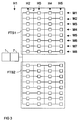
- the sensor-side transceiver 8 can the individual alarm sensors 2 of a radio hazard alarm system also communicate with each other, and it can be, for example, a radio hazard alarm system in Build the tree structure as shown in Figure 3.
- the central unit 1 has two radio subsystems FTS 1 and FTS 2 connected, the radio subsystems used for example by the radio transmission distinguish different frequency. In every radio subsystem there are 32 message sensors, which are hierarchical are connected to the central unit 1.
- the alarm sensors connected to the central unit 1 2 form the second hierarchical level H2, which with the Alarm sensors of the second hierarchy level H2 connected alarm sensors 2 form the third hierarchy level H3 etc.
- the individual message sensors become a hierarchy level 2 differentiated by specifying an additional detector number (M1..M8).
- M1..M8 By specifying the radio subsystem, the hierarchy level and the detector number is a unique address of the individual signal sensors 2 guaranteed.
- the concatenation of the individual signal sensors 2 is now ensured that each message sensor 2 both the address of a Message sensor 2 in a next higher hierarchy level such as the addresses of alarm sensors 2 in the next lower one Knows hierarchy levels with which he communicates.
- the message sensors 2 of the middle hierarchy levels therefore serve as Intermediate stations for the transmission of measurement data from the signal sensors 2 of the lower hierarchy levels to the central unit 1.
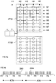
- Figure 4a are existing connections by broad lines featured.
- Fig.4b is the Time sequence of the associated telegram processing is shown, the identifier telegrams are in a first time period KTN KTN and in the subsequent time period ATN the response telegrams ZS transmitted in fixed time slots.
- Time slots are ZSM in which telegrams are transmitted are represented by wide lines and time slots ZSO, in which no telegrams are transmitted, through thin lines.
- the sequence in normal operation then takes place as follows, for example:
- the central unit 1 starts the transmission by sending an identifier telegram KT as a synchronization signal.
- the identifier telegram essentially contains the address of the central unit 1 as well as further information about the operating state of the radio hazard alarm system, which will be described in more detail later.
- the alarm sensors 2 of the second hierarchical level H2 are switched on by the alarm clock 12 shortly before the identification telegram KT is sent to the central unit 1 and all read this identification telegram KT at the same time.
- the start edge of the identifier telegram KT also serves as the system synchronization point in time, that is, from this point on, all further activities are defined with quartz precision.
- the message sensors 2 of the second hierarchical level H2 send their own identifier telegrams KT in succession; in FIGS. 4a, 4b it is the message sensors 2 with the message numbers M1, M2 and M5.
- the addresses transmitted in the process do not have to be fully occupied. If all addresses are occupied, the messages appear at a predetermined system time interval, otherwise there are corresponding gaps, as shown in Fig. 4b.
- the message sensors 2 of the third hierarchy level H3 receive these identification telegrams and compare them with the stored, assigned address of the message sensor 2 of the second hierarchy level H2, to which they are to transmit their reporting data.
- the alarm sensors 2 of the third hierarchy level H3, like the alarm sensors 2 of the second hierarchy level H2, are switched on by their alarm clocks 12.
- the receipt of the identifier telegram KT from the assigned signal sensor 2 of the upper hierarchy level triggers the measurement process its own detection device 3, so that afterwards a current value can be transferred to it. If all Have sent signal sensors 2 of the penultimate hierarchy level, that is, if the corresponding allotted broadcast time has expired, after a pause the return of the Measurement data started. The pause gives the last message sensor 2 Opportunity to activate its detection device 3. For the return of the measurement data in a reply telegram is AT a fixed time slot ZS is assigned to each signaling sensor. The Data transmission takes place in the reverse order to that Transmission of the identifier telegrams, i.e. it starts first the message sensors 2 of the lowest hierarchy level in a predetermined Order to send.
- the alarm sensors 2 of the upper one Hierarchy levels receive the measurement data from the signal sensors 2 the lower hierarchy and send both their own Measurement data as well as the measurement data received from the signaling sensors 2 of the lower hierarchical levels at the respective assigned Message sensor 2 of the upper hierarchy level continues until the measurement data have arrived in the central unit 1. After the transmission of the response telegram switches the alarm clock 12 the signal sensors to save electricity.
- a single alarm sensor 2 is not ready for operation, then he will not send an identifier telegram KT.
- the regulation applies that the own identification telegram is only for Receipt of the identifier telegram from the assigned alarm sensor 2 of the upper hierarchical level may be sent.
- the associated message sensors 2 of the lower hierarchy levels lame. Because each detector sensor 2 from its parameter set knows the downstream sensor 2, whose Reply telegram AT to the respective message sensor 2 must pass through the upper hierarchy level Signal sensors 2 of the next lower hierarchy level a fixed one Time window allocated for data reception. The receiving one Message sensor 2 now sets these time windows one after the other and tries to receive the measurement data.
- the transceiver In the initiation phase, for example, the transceiver becomes 8 switched on for 50 ⁇ s each and then switched off for 1s. The period of 50 ⁇ s is sufficient to settle the frequency synthesizer to let.
- a continuous signal (approx. 5s) is emitted.
- the essential task this continuous signal consists of all the signal sensors 2 Radio hazard detection system to draw your attention to the fact that there is radio operation at all. So it just comes up level detection, not on the correct reading of the continuous signal.
- Each signal sensor 2 which is a permanent signal from somewhere detected, follows the initiation phase and also sends a continuous signal. Then switches each signal sensor 2 for a longer time (approx.
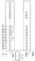
- FIG 5 is another embodiment of a Radio hazard detection system shown.
- the central unit 1 with individual alarm sensors 2 in type and Connected way that only in each radio subsystem AGVS a message sensor 2 is provided per hierarchy level.
- the individual Signaling sensors 2 spatially so closely staggered that not only the Message sensor 2 of the next hierarchy level, but also the Message sensor 2 of the next but one hierarchy level can be reached is.
- this radio alarm system how already described, first the identifier telegrams KT individual message sensors 2 sent in succession.
- the concatenation consists in the fact that the individual signal sensors 2 not just the identifier telegram of the signal sensor of the upper one Hierarchy level, but also the identifier telegram KT of the Message sensor 2, the two hierarchy levels arranged above is reads. In general, both identifier telegrams KT receive.
- Each detector sensor 2 is sufficient for this normal operation its response telegram AT to the message sensor of the top Hierarchy level continues, as is the case with the tree structure according to the figure 2 and 3 has already been set out.
- Alarm sensor 2 detects that it is from the failed alarm sensor 2 does not receive a response telegram AT, so it sets an additional reception time window for the message sensor 2 two hierarchy levels below, receives the response telegram AT, also sets information about the failed alarm sensor 2, and sends this data along with your own Measurement data than his answer telegram AT.
- the central unit 1 immediately recognizes the faulty one without additional actions Message sensor 2 on the additional information inserted.
- This chained willow branch structure is ideal for the narrow assembly of elongated buildings without large ones spatial interruption.
- the system is well manageable and robust, every second signaling sensor 2 can temporarily Function can be set without the radio hazard alarm system collapses.
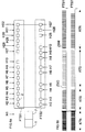
- FIGs 6a to 7b Another embodiment is in Figures 6a to 7b shown.
- the individual signal sensors 2 are in one Loop structure built.
- Both AGV radio subsystems are constructed analogously to the willow branch structure, i.e. in each Hierarchy level there is only one message sensor 2.
- Both radio subsystems AGVs work on the same radio channel.
- the message sensors 2 of the lowest hierarchy level are so closely arranged that they are together can communicate by radio.
- FIG 6b is the Time sequence of the telegram transmission in normal operation shown.
- the time slots ZS are each through vertical lines are shown, with time slots ZSM in which Telegrams are sent out by broad lines, and Time slots ZSO in which no telegrams are sent are marked with narrow lines.
- Time ranges KTN are analogous to those described so far Embodiments of the identifier telegrams KT of the individual Signaling sensors 2 are sent, the identification telegrams KT of the two radio subsystems FTS sent so that the identifier telegrams KT of the two systems against each other half a telegram increment are offset.
- the passage of time is also dimensioned so that the knowledge telegrams KT the last two signal sensors 2 in quick succession be sent. This fact is an essential part the loop redundancy and is closer with reference to Figure 7 explained.
- the reply telegrams AT are returned in fourth time period ATN, the individual time slots of the the two radio subsystems AGVs are in turn nested are.
- Intelligent time management makes time for the transmission of the response telegrams AT reduced by the length of the reserved time slots ZS the length of the Response telegrams AT are adapted.
- the query time is unsatisfactory.
- the system can be used in an analog form also use for intrusion detection systems. It is in one larger time interval in the manner already described and Way a function check and a synchronization of the individual signal sensors 2 reached.
- individual time slots are provided in which the individual alarm sensors when detecting a hazard message this to the respective assigned sensor 2 of the upper one Hierarchy level.
- These signal sensors 2 the upper hierarchical level then routes this data accordingly to central unit 1. To do this, the individual Signal sensors 2 in the time interval very precisely their respective Switch on transceiver 8.
- the transceiver detects 8 on missing reception and switches off, otherwise the received message will be allocated in your own Broadcast timeslot passed up one hierarchy level.
- the synchronization of the individual alarm clocks 12 in the Signaling sensors 2 will refer to this repetition time the central unit 1 achieved. Because of the short-term The transceiver 8 can be switched on therefore operate the individual alarm sensor 2 with a battery 6.
Landscapes
- Business, Economics & Management (AREA)
- Emergency Management (AREA)
- Physics & Mathematics (AREA)
- General Physics & Mathematics (AREA)
- Alarm Systems (AREA)
- Mobile Radio Communication Systems (AREA)
- Emergency Alarm Devices (AREA)
- Arrangements For Transmission Of Measured Signals (AREA)
Applications Claiming Priority (2)
| Application Number | Priority Date | Filing Date | Title |
|---|---|---|---|
| DE19640362 | 1996-09-30 | ||
| DE19640362 | 1996-09-30 |
Publications (3)
| Publication Number | Publication Date |
|---|---|
| EP0833288A2 true EP0833288A2 (fr) | 1998-04-01 |
| EP0833288A3 EP0833288A3 (fr) | 2000-01-19 |
| EP0833288B1 EP0833288B1 (fr) | 2003-08-20 |
Family
ID=7807485
Family Applications (1)
| Application Number | Title | Priority Date | Filing Date |
|---|---|---|---|
| EP97116269A Expired - Lifetime EP0833288B1 (fr) | 1996-09-30 | 1997-09-18 | Procédé pour la transmission radioélectrique de données des capteurs et système d'alarme radio |
Country Status (4)
| Country | Link |
|---|---|
| EP (1) | EP0833288B1 (fr) |
| AT (1) | ATE247856T1 (fr) |
| DE (1) | DE59710605D1 (fr) |
| ES (1) | ES2205106T3 (fr) |
Cited By (13)
| Publication number | Priority date | Publication date | Assignee | Title |
|---|---|---|---|---|
| EP1282095A2 (fr) | 2001-08-03 | 2003-02-05 | Siemens Gebäudesicherheit GmbH & Co. OHG | Procédé de communication radio dans un système d'alarme |
| EP1235192A3 (fr) * | 2001-02-27 | 2003-07-16 | BW Technologies Limited | Améliorations dans les systèmes de surveillance de gazes toxiques |
| FR2855297A1 (fr) * | 2003-05-19 | 2004-11-26 | Cedom | Systeme d'alarme sans fil et procede de transmission. |
| FR2855298A1 (fr) * | 2003-05-19 | 2004-11-26 | Cedom | Installation d'alarme sans fil a relais et procede de relayage. |
| FR2857141A1 (fr) * | 2003-05-19 | 2005-01-07 | Cedom | Installation d'alarme sans fil a faible consommation d'energie |
| FR2859301A1 (fr) * | 2003-08-25 | 2005-03-04 | Laudren Electricite Ind Marine | Procede et dispositif de detection de degazage de navires petroliers en mer |
| DE10317586B3 (de) * | 2003-04-16 | 2005-04-28 | Siemens Ag | Verfahren zur Funkübertragung in einem Gefahrenmeldesystem |
| EP1647956A2 (fr) | 2004-10-12 | 2006-04-19 | Siemens Aktiengesellschaft | Procédé de mise en service des systèmes sans fil pour signaler des dangers |
| US7363036B2 (en) | 2003-04-17 | 2008-04-22 | Siemens Aktiengesellschaft | Procedure for registering a new subscriber in a radio system through routers |
| US7483403B2 (en) | 2002-01-10 | 2009-01-27 | Robert Bosch Gmbh | Protocol for reliable, self-organizing, low-power wireless network for security and building automation systems |
| EP1177541B2 (fr) † | 1999-05-13 | 2009-06-24 | Honeywell Inc. | Reseau de commande sans fil dans lequel les emissions se font dans des tranches de temps programmees |
| NO20161779A1 (en) * | 2016-11-10 | 2018-05-11 | Sfty As | Safety detector and system for multi dwelling units and the like |
| EP3951732A4 (fr) * | 2019-03-27 | 2022-08-24 | Panasonic Intellectual Property Management Co., Ltd. | Système de détection, relais, procédé de détection, et programme |
Families Citing this family (1)
| Publication number | Priority date | Publication date | Assignee | Title |
|---|---|---|---|---|
| DE102004039675B4 (de) * | 2004-08-16 | 2006-11-23 | Siemens Ag | Verfahren zur Inbetriebsetzung von funkbasierten Gefahrenmeldesystemen |
Family Cites Families (9)
| Publication number | Priority date | Publication date | Assignee | Title |
|---|---|---|---|---|
| FR2531587A1 (fr) * | 1982-08-03 | 1984-02-10 | Morey Gilles | Procede pour la transmission d'informations sur un canal d'echanges unique et application de ce procede notamment a des dispositifs formant un systeme d'alarme |
| US4772876A (en) * | 1986-10-10 | 1988-09-20 | Zenith Electronics Corporation | Remote security transmitter address programmer |
| US5027314A (en) * | 1988-03-17 | 1991-06-25 | United Manufacturing Co., Inc. | Apparatus and method for position reporting |
| US4825457A (en) * | 1988-04-25 | 1989-04-25 | Lebowitz Mayer M | Cellular network data transmission system |
| US5390206A (en) * | 1991-10-01 | 1995-02-14 | American Standard Inc. | Wireless communication system for air distribution system |
| JP3029716B2 (ja) * | 1991-11-01 | 2000-04-04 | ホーチキ株式会社 | 無線式アナログ感知器 |
| FR2691274B1 (fr) * | 1992-05-13 | 1996-08-02 | Seb Sa | Capteur, centre de surveillance et reseau domotique de surveillance. |
| US5381136A (en) * | 1993-03-19 | 1995-01-10 | Northern Illinois Gas Company | Remote data collection and monitoring system for distribution line |
| DE4335815C2 (de) * | 1993-10-20 | 1996-08-08 | Hal Sicherheitstechnik Gmbh | Funkalarmanlage |
-
1997
- 1997-09-18 AT AT97116269T patent/ATE247856T1/de active
- 1997-09-18 ES ES97116269T patent/ES2205106T3/es not_active Expired - Lifetime
- 1997-09-18 DE DE59710605T patent/DE59710605D1/de not_active Expired - Lifetime
- 1997-09-18 EP EP97116269A patent/EP0833288B1/fr not_active Expired - Lifetime
Cited By (18)
| Publication number | Priority date | Publication date | Assignee | Title |
|---|---|---|---|---|
| EP1177541B2 (fr) † | 1999-05-13 | 2009-06-24 | Honeywell Inc. | Reseau de commande sans fil dans lequel les emissions se font dans des tranches de temps programmees |
| EP1235192A3 (fr) * | 2001-02-27 | 2003-07-16 | BW Technologies Limited | Améliorations dans les systèmes de surveillance de gazes toxiques |
| EP1282095A2 (fr) | 2001-08-03 | 2003-02-05 | Siemens Gebäudesicherheit GmbH & Co. OHG | Procédé de communication radio dans un système d'alarme |
| US8194571B2 (en) | 2002-01-10 | 2012-06-05 | Robert Bosch Gmbh | Protocol for reliable, self-organizing, low-power wireless network for security and building automation systems |
| US7483403B2 (en) | 2002-01-10 | 2009-01-27 | Robert Bosch Gmbh | Protocol for reliable, self-organizing, low-power wireless network for security and building automation systems |
| US7248854B2 (en) | 2003-04-16 | 2007-07-24 | Siemens Aktiengesellschaft | Method for radio transmission in an alarm signaling system |
| DE10317586B3 (de) * | 2003-04-16 | 2005-04-28 | Siemens Ag | Verfahren zur Funkübertragung in einem Gefahrenmeldesystem |
| US7363036B2 (en) | 2003-04-17 | 2008-04-22 | Siemens Aktiengesellschaft | Procedure for registering a new subscriber in a radio system through routers |
| FR2857141A1 (fr) * | 2003-05-19 | 2005-01-07 | Cedom | Installation d'alarme sans fil a faible consommation d'energie |
| FR2855298A1 (fr) * | 2003-05-19 | 2004-11-26 | Cedom | Installation d'alarme sans fil a relais et procede de relayage. |
| FR2855297A1 (fr) * | 2003-05-19 | 2004-11-26 | Cedom | Systeme d'alarme sans fil et procede de transmission. |
| FR2859301A1 (fr) * | 2003-08-25 | 2005-03-04 | Laudren Electricite Ind Marine | Procede et dispositif de detection de degazage de navires petroliers en mer |
| DE102004049704B3 (de) * | 2004-10-12 | 2006-06-22 | Siemens Ag | Verfahren zur Inbetriebsetzung von funkbasierten Gefahrenmeldesystemen |
| EP1647956A3 (fr) * | 2004-10-12 | 2008-01-16 | Siemens Aktiengesellschaft | Procédé de mise en service des systèmes sans fil pour signaler des dangers |
| EP1647956A2 (fr) | 2004-10-12 | 2006-04-19 | Siemens Aktiengesellschaft | Procédé de mise en service des systèmes sans fil pour signaler des dangers |
| NO20161779A1 (en) * | 2016-11-10 | 2018-05-11 | Sfty As | Safety detector and system for multi dwelling units and the like |
| NO342364B1 (en) * | 2016-11-10 | 2018-05-14 | Sfty As | Safety detector and system for multi dwelling units and the like |
| EP3951732A4 (fr) * | 2019-03-27 | 2022-08-24 | Panasonic Intellectual Property Management Co., Ltd. | Système de détection, relais, procédé de détection, et programme |
Also Published As
| Publication number | Publication date |
|---|---|
| ES2205106T3 (es) | 2004-05-01 |
| EP0833288B1 (fr) | 2003-08-20 |
| DE59710605D1 (de) | 2003-09-25 |
| ATE247856T1 (de) | 2003-09-15 |
| EP0833288A3 (fr) | 2000-01-19 |
Similar Documents
| Publication | Publication Date | Title |
|---|---|---|
| EP0833288B1 (fr) | Procédé pour la transmission radioélectrique de données des capteurs et système d'alarme radio | |
| DE3342430C2 (fr) | ||
| DE68924615T2 (de) | Überwachungssystem für Funkkommunikationsapparate. | |
| DE2354067C3 (de) | Verfarhen und Einrichtung zum Fernsteuern von Objekten | |
| EP2215614B1 (fr) | Procédé pour la transmission de données entre une unité de commande et une pluralité d'unités d'e/s décentralisées d'une installation automatisée | |
| EP1282094B1 (fr) | Méthode de transmission hertzienne dans un système d'alarme | |
| EP1216466B1 (fr) | Capteur avec transmission de donnees sans fil et faible consommation d'energie | |
| EP0267528B1 (fr) | Système numérique de transmission de données comprenant des répéteurs adressables et des dispositifs de localisation d'erreurs | |
| DE112005000779B4 (de) | Verfahren zur Synchronisation von Takteinrichtungen | |
| DE2449660C3 (de) | Verfahren und Einrichtung zur Synchronisation von im Zeitmultiplex arbeitenden, untereinander gleichberechtigten autonomen Geberstationen | |
| EP0033932A1 (fr) | Surveillance et localisation combinées des défauts dans des voies de transmission pour signaux numériques | |
| DE4005354C2 (fr) | ||
| EP1901256A1 (fr) | Procédé destiné à la transmission radio dans une cellule de système de détection des dangers | |
| DE102010032369B4 (de) | Anmeldeverfahren für Funkkommunikationssysteme | |
| DE2264085C2 (de) | Fernwirkanlage mit wenigstens einer Hauptzentrale, der ein Hauptnetz zugeordnet ist | |
| EP0962904A2 (fr) | Procédé de transmission de données entre au moins deux unités émettrices et au moins une unité de réception sur au moins un canal de transmission | |
| DE2410380C3 (de) | Ortungssystem mit miteinander in Verbindung stehenden Ortungsgeräten ohne Zentralstelle | |
| EP0901299A2 (fr) | Dispositif de télécommunication numérique | |
| EP0536539B1 (fr) | Réseau d'appel radio pour la transmission de signaux d'appel radio relatifs aux abonnés et méthode pour son exploitation | |
| DE2725152C2 (de) | Überwachungssystem für elektronische Baugruppen oder Geräte in drahtgebundenen Fernmeldeanlagen | |
| DE69023689T2 (de) | Übertragungsadapter für das Endgerät eines Fernwirksystems. | |
| EP1282095B1 (fr) | Procédé de communication radio dans un système d'alarme | |
| DE3029803A1 (de) | Kabelfernsehsystem | |
| DE3207397A1 (de) | Verfahren zur ueberwachung der funktionsfaehigkeit einer digitalen uebertragungsstrecke | |
| EP0054643A1 (fr) | Dispositif de télésurveillance comprenant au moins un arrangement pour la transmission de messages selon un procédé multiplex temporel et en fréquence |
Legal Events
| Date | Code | Title | Description |
|---|---|---|---|
| PUAI | Public reference made under article 153(3) epc to a published international application that has entered the european phase |
Free format text: ORIGINAL CODE: 0009012 |
|
| AK | Designated contracting states |
Kind code of ref document: A2 Designated state(s): AT BE CH DE ES FR GB IT LI NL SE |
|
| PUAL | Search report despatched |
Free format text: ORIGINAL CODE: 0009013 |
|
| AK | Designated contracting states |
Kind code of ref document: A3 Designated state(s): AT BE CH DE DK ES FI FR GB GR IE IT LI LU MC NL PT SE |
|
| 17P | Request for examination filed |
Effective date: 20000717 |
|
| AKX | Designation fees paid |
Free format text: AT BE CH DE ES FR GB IT LI NL SE |
|
| 17Q | First examination report despatched |
Effective date: 20020221 |
|
| GRAH | Despatch of communication of intention to grant a patent |
Free format text: ORIGINAL CODE: EPIDOS IGRA |
|
| GRAS | Grant fee paid |
Free format text: ORIGINAL CODE: EPIDOSNIGR3 |
|
| GRAA | (expected) grant |
Free format text: ORIGINAL CODE: 0009210 |
|
| AK | Designated contracting states |
Designated state(s): AT BE CH DE ES FR GB IT LI NL SE |
|
| REG | Reference to a national code |
Ref country code: GB Ref legal event code: FG4D Free format text: NOT ENGLISH |
|
| REG | Reference to a national code |
Ref country code: CH Ref legal event code: EP |
|
| REG | Reference to a national code |
Ref country code: CH Ref legal event code: NV Representative=s name: SERVOPATENT GMBH |
|
| REF | Corresponds to: |
Ref document number: 59710605 Country of ref document: DE Date of ref document: 20030925 Kind code of ref document: P |
|
| REG | Reference to a national code |
Ref country code: SE Ref legal event code: TRGR |
|
| GBT | Gb: translation of ep patent filed (gb section 77(6)(a)/1977) |
Effective date: 20031118 |
|
| REG | Reference to a national code |
Ref country code: ES Ref legal event code: FG2A Ref document number: 2205106 Country of ref document: ES Kind code of ref document: T3 |
|
| ET | Fr: translation filed | ||
| PLBE | No opposition filed within time limit |
Free format text: ORIGINAL CODE: 0009261 |
|
| STAA | Information on the status of an ep patent application or granted ep patent |
Free format text: STATUS: NO OPPOSITION FILED WITHIN TIME LIMIT |
|
| 26N | No opposition filed |
Effective date: 20040524 |
|
| REG | Reference to a national code |
Ref country code: CH Ref legal event code: PCAR Free format text: SIEMENS SCHWEIZ AG;INTELLECTUAL PROPERTY FREILAGERSTRASSE 40;8047 ZUERICH (CH) |
|
| PGFP | Annual fee paid to national office [announced via postgrant information from national office to epo] |
Ref country code: BE Payment date: 20111013 Year of fee payment: 15 Ref country code: ES Payment date: 20111013 Year of fee payment: 15 |
|
| PGFP | Annual fee paid to national office [announced via postgrant information from national office to epo] |
Ref country code: GB Payment date: 20120917 Year of fee payment: 16 Ref country code: SE Payment date: 20120911 Year of fee payment: 16 |
|
| PGFP | Annual fee paid to national office [announced via postgrant information from national office to epo] |
Ref country code: IT Payment date: 20120927 Year of fee payment: 16 |
|
| PGFP | Annual fee paid to national office [announced via postgrant information from national office to epo] |
Ref country code: NL Payment date: 20120911 Year of fee payment: 16 Ref country code: AT Payment date: 20120810 Year of fee payment: 16 |
|
| BERE | Be: lapsed |
Owner name: *SIEMENS A.G. Effective date: 20120930 |
|
| PG25 | Lapsed in a contracting state [announced via postgrant information from national office to epo] |
Ref country code: BE Free format text: LAPSE BECAUSE OF NON-PAYMENT OF DUE FEES Effective date: 20120930 |
|
| REG | Reference to a national code |
Ref country code: ES Ref legal event code: FD2A Effective date: 20131022 |
|
| REG | Reference to a national code |
Ref country code: NL Ref legal event code: V1 Effective date: 20140401 |
|
| REG | Reference to a national code |
Ref country code: SE Ref legal event code: EUG |
|
| PG25 | Lapsed in a contracting state [announced via postgrant information from national office to epo] |
Ref country code: SE Free format text: LAPSE BECAUSE OF NON-PAYMENT OF DUE FEES Effective date: 20130919 |
|
| REG | Reference to a national code |
Ref country code: AT Ref legal event code: MM01 Ref document number: 247856 Country of ref document: AT Kind code of ref document: T Effective date: 20130918 |
|
| GBPC | Gb: european patent ceased through non-payment of renewal fee |
Effective date: 20130918 |
|
| PG25 | Lapsed in a contracting state [announced via postgrant information from national office to epo] |
Ref country code: ES Free format text: LAPSE BECAUSE OF NON-PAYMENT OF DUE FEES Effective date: 20120919 |
|
| PG25 | Lapsed in a contracting state [announced via postgrant information from national office to epo] |
Ref country code: GB Free format text: LAPSE BECAUSE OF NON-PAYMENT OF DUE FEES Effective date: 20130918 |
|
| PG25 | Lapsed in a contracting state [announced via postgrant information from national office to epo] |
Ref country code: IT Free format text: LAPSE BECAUSE OF NON-PAYMENT OF DUE FEES Effective date: 20130918 Ref country code: NL Free format text: LAPSE BECAUSE OF NON-PAYMENT OF DUE FEES Effective date: 20140401 Ref country code: AT Free format text: LAPSE BECAUSE OF NON-PAYMENT OF DUE FEES Effective date: 20130918 |
|
| PGFP | Annual fee paid to national office [announced via postgrant information from national office to epo] |
Ref country code: FR Payment date: 20140917 Year of fee payment: 18 Ref country code: CH Payment date: 20141204 Year of fee payment: 18 Ref country code: DE Payment date: 20141120 Year of fee payment: 18 |
|
| REG | Reference to a national code |
Ref country code: CH Ref legal event code: PUE Owner name: SIEMENS SCHWEIZ AG, CH Free format text: FORMER OWNER: SIEMENS AKTIENGESELLSCHAFT, DE |
|
| REG | Reference to a national code |
Ref country code: DE Ref legal event code: R081 Ref document number: 59710605 Country of ref document: DE Owner name: SIEMENS SCHWEIZ AG, CH Free format text: FORMER OWNER: SIEMENS AKTIENGESELLSCHAFT, 80333 MUENCHEN, DE Effective date: 20150407 |
|
| REG | Reference to a national code |
Ref country code: FR Ref legal event code: TP Owner name: SIEMENS SCHWEIZ AG, CH Effective date: 20160202 |
|
| REG | Reference to a national code |
Ref country code: DE Ref legal event code: R119 Ref document number: 59710605 Country of ref document: DE |
|
| REG | Reference to a national code |
Ref country code: CH Ref legal event code: PL |
|
| REG | Reference to a national code |
Ref country code: FR Ref legal event code: ST Effective date: 20160531 |
|
| PG25 | Lapsed in a contracting state [announced via postgrant information from national office to epo] |
Ref country code: LI Free format text: LAPSE BECAUSE OF NON-PAYMENT OF DUE FEES Effective date: 20150930 Ref country code: CH Free format text: LAPSE BECAUSE OF NON-PAYMENT OF DUE FEES Effective date: 20150930 Ref country code: DE Free format text: LAPSE BECAUSE OF NON-PAYMENT OF DUE FEES Effective date: 20160401 |
|
| PG25 | Lapsed in a contracting state [announced via postgrant information from national office to epo] |
Ref country code: FR Free format text: LAPSE BECAUSE OF NON-PAYMENT OF DUE FEES Effective date: 20150930 |