EP0833420A2 - Dispositif d'étanchéité pour appareil électrique protégé contre les projections d'eau - Google Patents
Dispositif d'étanchéité pour appareil électrique protégé contre les projections d'eau Download PDFInfo
- Publication number
- EP0833420A2 EP0833420A2 EP97114715A EP97114715A EP0833420A2 EP 0833420 A2 EP0833420 A2 EP 0833420A2 EP 97114715 A EP97114715 A EP 97114715A EP 97114715 A EP97114715 A EP 97114715A EP 0833420 A2 EP0833420 A2 EP 0833420A2
- Authority
- EP
- European Patent Office
- Prior art keywords
- sealing
- frame
- arrangement according
- cover frame
- sealing element
- Prior art date
- Legal status (The legal status is an assumption and is not a legal conclusion. Google has not performed a legal analysis and makes no representation as to the accuracy of the status listed.)
- Granted
Links
Images



Classifications
-
- H—ELECTRICITY
- H02—GENERATION; CONVERSION OR DISTRIBUTION OF ELECTRIC POWER
- H02G—INSTALLATION OF ELECTRIC CABLES OR LINES, OR OF COMBINED OPTICAL AND ELECTRIC CABLES OR LINES
- H02G3/00—Installations of electric cables or lines or protective tubing therefor in or on buildings, equivalent structures or vehicles
- H02G3/02—Details
- H02G3/08—Distribution boxes; Connection or junction boxes
- H02G3/088—Dustproof, splashproof, drip-proof, waterproof, or flameproof casings or inlets
-
- H—ELECTRICITY
- H01—ELECTRIC ELEMENTS
- H01H—ELECTRIC SWITCHES; RELAYS; SELECTORS; EMERGENCY PROTECTIVE DEVICES
- H01H23/00—Tumbler or rocker switches, i.e. switches characterised by being operated by rocking an operating member in the form of a rocker button
- H01H23/02—Details
- H01H23/04—Cases; Covers
- H01H23/06—Dustproof, splashproof, drip-proof, waterproof, or flameproof casings
-
- H—ELECTRICITY
- H01—ELECTRIC ELEMENTS
- H01R—ELECTRICALLY-CONDUCTIVE CONNECTIONS; STRUCTURAL ASSOCIATIONS OF A PLURALITY OF MUTUALLY-INSULATED ELECTRICAL CONNECTING ELEMENTS; COUPLING DEVICES; CURRENT COLLECTORS
- H01R13/00—Details of coupling devices of the kinds covered by groups H01R12/70 or H01R24/00 - H01R33/00
- H01R13/46—Bases; Cases
- H01R13/52—Dustproof, splashproof, drip-proof, waterproof, or flameproof cases
- H01R13/5213—Covers
-
- H—ELECTRICITY
- H01—ELECTRIC ELEMENTS
- H01R—ELECTRICALLY-CONDUCTIVE CONNECTIONS; STRUCTURAL ASSOCIATIONS OF A PLURALITY OF MUTUALLY-INSULATED ELECTRICAL CONNECTING ELEMENTS; COUPLING DEVICES; CURRENT COLLECTORS
- H01R2103/00—Two poles
-
- H—ELECTRICITY
- H01—ELECTRIC ELEMENTS
- H01R—ELECTRICALLY-CONDUCTIVE CONNECTIONS; STRUCTURAL ASSOCIATIONS OF A PLURALITY OF MUTUALLY-INSULATED ELECTRICAL CONNECTING ELEMENTS; COUPLING DEVICES; CURRENT COLLECTORS
- H01R24/00—Two-part coupling devices, or either of their cooperating parts, characterised by their overall structure
- H01R24/76—Two-part coupling devices, or either of their cooperating parts, characterised by their overall structure with sockets, clips or analogous contacts and secured to apparatus or structure, e.g. to a wall
- H01R24/78—Two-part coupling devices, or either of their cooperating parts, characterised by their overall structure with sockets, clips or analogous contacts and secured to apparatus or structure, e.g. to a wall with additional earth or shield contacts
Definitions
- the present invention relates to a sealing arrangement for splash-proof electrical installation devices in Flush-mounted version, especially for sockets and / or Switch, wherein a first sealing element for sealing between a support ring one can be inserted into a flush-mounted box Device base and a cover frame as well as a second sealing element for sealing between the cover frame and a central insert element are provided.
- the well-known Sealing arrangement leads to in all embodiments a large manufacturing and assembly effort, especially because of specially adapted to accommodate the sealing elements Device parts required for the water-protected version are.
- the design and Housing the seals also a disadvantageously large Overall height.
- the present invention has for its object a To create sealing arrangement of the type mentioned Made inexpensively and in a quick and easy way Wise - can also be retrofitted if necessary - can be assembled.
- first Sealing element in one piece over a transition section with the second sealing element to form an integral sealing part connected is. It is useful if that first sealing element as a flat, frame-like in particular Rectangular section for flat arrangement is formed between the support ring and the cover frame.
- This embodiment of the invention is first advantageously only a single integrally formed Sealing part required, which is inexpensive - as Molding in particular made of silicone or the like and is quick and easy to assemble.
- the sealing part according to the invention is therefore also suitable for retrofitting from original non-splash-proof devices, their cover frames with an essentially flat contact surface - and originally without seal - is formed.
- Mainly by the first sealing element designed as a flat seal is also a low profile, d. H. a little Wall protrusion reached.
- the second, according to the invention via the transition section integrally connected to the first sealing element Sealing element is for use with a socket on the one hand and with a switch on the other trained differently. This is said below in the Description of preferred embodiments in more detail are explained.
- FIG. 1 are the individual parts of a first embodiment an electrical installation device illustrated; it is a flush-mounted socket (UP-SCHUKO socket).
- a device base 2 is in a not shown Flush-mounted box can be used.
- the device base 2 has one Support ring 4, which in the inserted state on the Flush box surrounding mounting surface, usually one Wall surface, rests.
- the support ring 4 is then with a Cover frame 6 covered.
- a Central insert element 8 used, which in this Version a socket pot 10 (so-called SCHUKO pot), an edge region 12 surrounding the socket pot 10 and in particular because of the splash-proof design has a hinged lid 14.
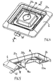
- an inventive integrally formed sealing part 16 is provided, which is a first sealing element 18 for sealing between the support ring 4 of the device base 2 and the cover frame 6 and a second sealing element 20 for sealing between the cover frame 6 and the central insert element 8 has.
- the two Sealing elements 18, 20 in one piece via a transition section 22 connected together.
- the first sealing element 18 is as flat, frame-like and in adaptation to the support ring 4 and the cover frame 6 in particular rectangular circumferential section for flat arrangement between the support ring 4 and the cover frame 6 are formed.
- the integral sealing part 16 accordingly frame-shaped, the second Sealing element 20 flat and also corresponding frame-like, in particular, rectangular, and with Distance essentially parallel to the first sealing element 18 lying to the flat arrangement between one inner edge web 24 of the cover frame 6 and the edge area 12 of the central insert element 8 is formed.
- the Transition section 22 forms in this embodiment one essentially perpendicular to the two flat ones Sealing elements 18, 20 arranged, circumferential connecting web 26 (see also Fig. 2). So that points Sealing part 16 in this embodiment a U-shaped Profile cross-section so that the sealing part 16 according to 2 on the inner edge web 24 of the cover frame 6 can be put on and preassembled.
- sealing part 16 advantageously result in inexpensive manufacture as well as easy assembly because the individual parts of the Installation device just made as well need to be assembled as if no seal was provided would. Nevertheless, the sealing part according to the invention 16 and its captively pre-assembled arrangement on the inner edge web 24 of the cover frame 6 a safe Splash water seal according to IP 44 guaranteed. Also existing, originally not water-protected installation devices can easily with the sealing part 16 retrofitted and thus in a water-protected version be converted.
- Both sealing elements 18, 20 are by the attachment, in particular screw fastening, the central insert element 8 pressed on device base 2.
- an is preferably on known additional sealing flange 28 for arrangement between the support ring 4 and the surrounding the flush box Mounting area provided.
- This sealing flange 28 is usually in one piece with one in the flush-mounted box engaging and enclosing the inserted device base 2, essentially annular collar 30 connected.
- the installation device is in one embodiment illustrated as a switch (rocker switch).
- the as Switch trained device base 2a in turn has the Support ring 4 on.
- the cover frame 6 corresponds essentially the embodiment according to Fig. 1.
- the central insert element is designed here as an operating rocker, which is why here, in contrast to FIG. 1, reference number 8a is used has been.
- the one-piece sealing part according to the invention differs from the embodiment according to FIG. 1, which is why it is provided with the reference number 16a in FIG. 3.
- the second sealing element 20a hood-like, essentially rectangular or cuboid, to cover the area of at least one rocker switch 32 of the device base 2a is formed.
- the hood-shaped second sealing element 20a has a through opening 34 for a connection approach engaging in the rocker switch 32 36 (see Fig. 7) of the as a rocker trained central insert element 8a.
- the sealing part 16a forms one Type labyrinth seal that allows controlled water drainage only allowed outside, water penetration effectively prevented into the interior of the device.
- a frame-shaped Pressing element 38 for pressing the cover frame 6 against the support ring 4 of the device base 2a with an intermediate layer of the first sealing element 18 of the integral sealing part 16a provided.
- the pressure element 38 has advantageously also bearing approaches 40 for tilting storage the operating rocker (8a); see also Fig. 6.
- the Pressure element 38 is expediently by means of screws 42 screwed to the device base 2a.
- the transition section 22a of the sealing part 16a flat and such framing like a frame and especially in one opposite the flat first sealing element 18 from the device base 2a lying away in a substantially parallel offset plane trained that he - especially for positioning - in one enclosed by the inner edge web 24 of the cover frame 6 Frame opening 44 engages.
- the layer offset between the first sealing element 18 and the Transition section 22a is also preferably reached, that the pressure element 38 after assembly in some areas on the Transitional section 22a comes to rest. It follows this creates an additional sealing effect.
- the integral Sealing part 16 or 16a preferably a Outer edge in particular of the first sealing element 18 connected and in the assembled state the cover frame 6 marking tab 48 projecting outwards.
- This Identification tab 48 can in the area of the cover frame 6 outstanding labeling in particular the degree of protection, e.g. B. "IP 44" wear. It gives her gives the user direct information about the type of installation device. After or during assembly, the Identification flap 48 are of course removed, for example by cutting. But it can be beneficial be a kind of predetermined breaking point or predetermined breaking point form to easily remove the tab 48 without tools to be able to.
Landscapes
- Engineering & Computer Science (AREA)
- Architecture (AREA)
- Civil Engineering (AREA)
- Structural Engineering (AREA)
- Switch Cases, Indication, And Locking (AREA)
- Patch Boards (AREA)
- Distribution Board (AREA)
- Electrical Discharge Machining, Electrochemical Machining, And Combined Machining (AREA)
- Casings For Electric Apparatus (AREA)
- Connector Housings Or Holding Contact Members (AREA)
Applications Claiming Priority (2)
| Application Number | Priority Date | Filing Date | Title |
|---|---|---|---|
| DE29616958U | 1996-09-28 | ||
| DE29616958U DE29616958U1 (de) | 1996-09-28 | 1996-09-28 | Dichtungsanordnung für spritzwassergeschützte Elektro-Installationsgeräte |
Publications (3)
| Publication Number | Publication Date |
|---|---|
| EP0833420A2 true EP0833420A2 (fr) | 1998-04-01 |
| EP0833420A3 EP0833420A3 (fr) | 1999-09-29 |
| EP0833420B1 EP0833420B1 (fr) | 2002-11-13 |
Family
ID=8029906
Family Applications (1)
| Application Number | Title | Priority Date | Filing Date |
|---|---|---|---|
| EP97114715A Expired - Lifetime EP0833420B1 (fr) | 1996-09-28 | 1997-08-26 | Dispositif d'étanchéité pour appareil électrique protégé contre les projections d'eau |
Country Status (4)
| Country | Link |
|---|---|
| EP (1) | EP0833420B1 (fr) |
| AT (1) | ATE227895T1 (fr) |
| CZ (1) | CZ286021B6 (fr) |
| DE (2) | DE29616958U1 (fr) |
Cited By (10)
| Publication number | Priority date | Publication date | Assignee | Title |
|---|---|---|---|---|
| DE19816728A1 (de) * | 1998-04-16 | 1999-10-21 | Abb Patent Gmbh | Elektrisches wassergeschütztes Unterputzinstallationsgerät |
| FR2841433A1 (fr) * | 2002-06-19 | 2003-12-26 | Meta Srl | Ensemble armature-plaque pour les dispositifs electriques |
| ES2204228A1 (es) * | 2000-04-25 | 2004-04-16 | BERKER GMBH & CO KG. | Marco de recubrimiento estructurado para aparatos empotrados de instalaciones electricas. |
| FR2875062A1 (fr) * | 2004-09-06 | 2006-03-10 | Arnould Sa | Gamme rationalisee d'appareillages electriques |
| EP1635435A1 (fr) | 2004-09-09 | 2006-03-15 | Albrecht Jung GmbH & Co. KG | Unité d'installation électrique/électronique |
| EP1635434A1 (fr) * | 2004-09-09 | 2006-03-15 | Albrecht Jung GmbH & Co. KG | Unité d'installation électrique/électronique |
| ITPI20090122A1 (it) * | 2009-10-13 | 2011-04-14 | Pro One Srl | Presa telefonica a basso profilo |
| CN101247006B (zh) * | 2007-02-15 | 2011-11-09 | 浙江康泰电气有限公司 | 一种防水插头插座 |
| WO2013186683A1 (fr) * | 2012-06-12 | 2013-12-19 | Tyco Electronics Amp Gmbh | Joint, boîtier de connecteur et connecteur |
| DE102018122800A1 (de) * | 2018-09-18 | 2020-03-19 | Tehalit Gmbh | Geräteeinbaudose für Kabelkanäle mit verschwenkbarem Rahmen |
Families Citing this family (15)
| Publication number | Priority date | Publication date | Assignee | Title |
|---|---|---|---|---|
| FR2769124B1 (fr) * | 1997-09-29 | 1999-12-10 | Legrand Sa | Habillage pour appareillage electrique |
| DE19815788A1 (de) * | 1998-04-08 | 1999-10-21 | Abb Patent Gmbh | Elektrisches wassergeschütztes Unterputzinstallationsgerät |
| DE19858982C1 (de) * | 1998-12-19 | 2000-04-13 | Ellenberger & Poensgen | Elektrisches Schaltgerät zur Anordnung in einer Einbauöffnung |
| DE19942803B4 (de) * | 1999-09-08 | 2012-06-14 | Abb Ag | Elektrisches Installationsgerät |
| FR2823905B1 (fr) * | 2001-04-23 | 2004-01-30 | Legrand Sa | Dispositif de commande d'appareillages electriques etanche |
| DE20212323U1 (de) | 2001-08-10 | 2002-11-07 | ALRE-IT Regeltechnik GmbH, 10551 Berlin | Einrichtung zur Lagerung |
| DE10200939B4 (de) * | 2002-01-12 | 2018-11-08 | Merten Gmbh & Co. Kg | Elektrisches Installationsgerät |
| JP2004327169A (ja) | 2003-04-23 | 2004-11-18 | Yazaki Corp | パッキンとパッキンを備えたコネクタ |
| DE202006006453U1 (de) | 2006-04-21 | 2006-08-17 | Gira Giersiepen Gmbh & Co. Kg | Elektro-Installationssystem |
| FR3003121B1 (fr) | 2013-03-08 | 2016-12-30 | Legrand France | Support d'appareillage electrique et appareillage electrique comprenant un tel support |
| DE102014119271A1 (de) * | 2014-12-19 | 2016-06-23 | Schneider Electric Industries Sas | Elektrisches Installationsgerät |
| CN105896214A (zh) * | 2016-06-17 | 2016-08-24 | 无锡美羊动力科技有限公司 | 一种防水插排 |
| FR3105562B1 (fr) * | 2019-12-20 | 2022-01-07 | Legrand France | Enjoliveur et commutateur électrique comprenant un tel enjoliveur |
| EP3859919B1 (fr) * | 2020-01-30 | 2025-12-31 | Berker GmbH & Co. KG | Dispositif électrique |
| EP4510163A1 (fr) * | 2023-08-17 | 2025-02-19 | Abb Schweiz Ag | Ensemble commutateur pour usage domestique |
Family Cites Families (2)
| Publication number | Priority date | Publication date | Assignee | Title |
|---|---|---|---|---|
| DE3107791A1 (de) * | 1981-02-28 | 1982-09-16 | Fa. Albrecht Jung, 5885 Schalksmühle | "wassergeschuetztes installationsgeraet fuer unterputzmontage" |
| FR2747851B1 (fr) * | 1996-04-19 | 1998-07-03 | Arnould App Electr | Boite de sol, notamment pour appareillage electrique |
-
1996
- 1996-09-28 DE DE29616958U patent/DE29616958U1/de not_active Expired - Lifetime
-
1997
- 1997-08-26 DE DE59708706T patent/DE59708706D1/de not_active Expired - Fee Related
- 1997-08-26 EP EP97114715A patent/EP0833420B1/fr not_active Expired - Lifetime
- 1997-08-26 AT AT97114715T patent/ATE227895T1/de not_active IP Right Cessation
- 1997-09-26 CZ CZ973043A patent/CZ286021B6/cs not_active IP Right Cessation
Cited By (10)
| Publication number | Priority date | Publication date | Assignee | Title |
|---|---|---|---|---|
| DE19816728A1 (de) * | 1998-04-16 | 1999-10-21 | Abb Patent Gmbh | Elektrisches wassergeschütztes Unterputzinstallationsgerät |
| ES2204228A1 (es) * | 2000-04-25 | 2004-04-16 | BERKER GMBH & CO KG. | Marco de recubrimiento estructurado para aparatos empotrados de instalaciones electricas. |
| FR2841433A1 (fr) * | 2002-06-19 | 2003-12-26 | Meta Srl | Ensemble armature-plaque pour les dispositifs electriques |
| FR2875062A1 (fr) * | 2004-09-06 | 2006-03-10 | Arnould Sa | Gamme rationalisee d'appareillages electriques |
| EP1635435A1 (fr) | 2004-09-09 | 2006-03-15 | Albrecht Jung GmbH & Co. KG | Unité d'installation électrique/électronique |
| EP1635434A1 (fr) * | 2004-09-09 | 2006-03-15 | Albrecht Jung GmbH & Co. KG | Unité d'installation électrique/électronique |
| CN101247006B (zh) * | 2007-02-15 | 2011-11-09 | 浙江康泰电气有限公司 | 一种防水插头插座 |
| ITPI20090122A1 (it) * | 2009-10-13 | 2011-04-14 | Pro One Srl | Presa telefonica a basso profilo |
| WO2013186683A1 (fr) * | 2012-06-12 | 2013-12-19 | Tyco Electronics Amp Gmbh | Joint, boîtier de connecteur et connecteur |
| DE102018122800A1 (de) * | 2018-09-18 | 2020-03-19 | Tehalit Gmbh | Geräteeinbaudose für Kabelkanäle mit verschwenkbarem Rahmen |
Also Published As
| Publication number | Publication date |
|---|---|
| DE59708706D1 (de) | 2002-12-19 |
| EP0833420A3 (fr) | 1999-09-29 |
| EP0833420B1 (fr) | 2002-11-13 |
| CZ286021B6 (cs) | 1999-12-15 |
| DE29616958U1 (de) | 1996-11-14 |
| CZ304397A3 (cs) | 1998-04-15 |
| ATE227895T1 (de) | 2002-11-15 |
Similar Documents
| Publication | Publication Date | Title |
|---|---|---|
| EP0833420B1 (fr) | Dispositif d'étanchéité pour appareil électrique protégé contre les projections d'eau | |
| DE69207870T2 (de) | Verbindergehäuse | |
| DE3440899C1 (de) | Schaltschrank mit einem boxartigen Schrankkorpus und mit einer die OEffnung desselben verschliessenden Schranktuer | |
| EP1129460A1 (fr) | Commutateur electrique | |
| EP0122465A2 (fr) | Commutateur électrique ou bouton poussoir contenant deux bascules à grande surface | |
| DE69924154T2 (de) | Gerätegehalter ,insbesondere für elektrisches gerät und damit ausgerüstetes gehäuse | |
| DE19636500C2 (de) | Wassergeschütztes Installationsgerät | |
| DE69407249T2 (de) | Gehäuse für elektrische Einrichtung | |
| DE10139356A1 (de) | Elektrische Bauelementanordnung | |
| DE69833174T2 (de) | Durchführungsvorrichtung, insbesondere für Gehäuse elektrischer Geräte | |
| DE69606757T2 (de) | Vorrichtung mit schützender Wirkung gegen Durchsickern von Flüssigkeiten in elektrischen Schaltern und dergleichen | |
| WO2004075366A1 (fr) | Passage de cables | |
| DE69707344T2 (de) | Bodendose für elektrische Geräte | |
| DE69408275T2 (de) | Kippschalter mit Schützkappe | |
| EP0552780A1 (fr) | Boîtier de connexion électrique | |
| DE2037779C3 (de) | Wassergeschützte Aufputzdose | |
| DE29616794U1 (de) | Abdeckung für ein Lichtsignalgerät | |
| EP0508175A2 (fr) | Boîte de distribution à but électro-technique à monter sur crépi | |
| DE19639254A1 (de) | Wassergeschütztes elektrisches Installationsgerät | |
| EP0401556B1 (fr) | Boîtier encastré pour l'installation des appareils encastrés, en particulier des appareils électriques | |
| DE19723032C1 (de) | Abgedichtete Kabeleinführung | |
| DE4216350C1 (en) | Industrial electronic appts. housing - has interchangeable front frame cooperating with perpendicular lip of appts. housing enclosing front opening to provide water-tight seal | |
| EP0675583B1 (fr) | Matériel pour montage en surface d'un élément électrique tel qu'interrupteur, prise ou similaire | |
| EP0091620B1 (fr) | Dispositif pour l'assemblage sans boulon de deux parties de boîtier d'un appareil d'installation | |
| DE3002441C2 (de) | Elektrischer Installationsschalter mit einem Profilhalbzylinderschloß |
Legal Events
| Date | Code | Title | Description |
|---|---|---|---|
| PUAI | Public reference made under article 153(3) epc to a published international application that has entered the european phase |
Free format text: ORIGINAL CODE: 0009012 |
|
| AK | Designated contracting states |
Kind code of ref document: A2 Designated state(s): AT DE IT NL |
|
| TCNL | Nl: translation of patent claims filed | ||
| PUAL | Search report despatched |
Free format text: ORIGINAL CODE: 0009013 |
|
| AK | Designated contracting states |
Kind code of ref document: A3 Designated state(s): AT BE CH DE DK ES FI FR GB GR IE IT LI LU MC NL PT SE |
|
| 17P | Request for examination filed |
Effective date: 19991112 |
|
| AKX | Designation fees paid |
Free format text: AT DE IT NL |
|
| GRAG | Despatch of communication of intention to grant |
Free format text: ORIGINAL CODE: EPIDOS AGRA |
|
| 17Q | First examination report despatched |
Effective date: 20020304 |
|
| GRAG | Despatch of communication of intention to grant |
Free format text: ORIGINAL CODE: EPIDOS AGRA |
|
| GRAH | Despatch of communication of intention to grant a patent |
Free format text: ORIGINAL CODE: EPIDOS IGRA |
|
| GRAH | Despatch of communication of intention to grant a patent |
Free format text: ORIGINAL CODE: EPIDOS IGRA |
|
| GRAA | (expected) grant |
Free format text: ORIGINAL CODE: 0009210 |
|
| AK | Designated contracting states |
Kind code of ref document: B1 Designated state(s): AT DE IT NL |
|
| PG25 | Lapsed in a contracting state [announced via postgrant information from national office to epo] |
Ref country code: IT Free format text: LAPSE BECAUSE OF FAILURE TO SUBMIT A TRANSLATION OF THE DESCRIPTION OR TO PAY THE FEE WITHIN THE PRE;WARNING: LAPSES OF ITALIAN PATENTS WITH EFFECTIVE DATE BEFORE 2007 MAY HAVE OCCURRED AT ANY TIME BEFORE 2007. THE CORRECT EFFECTIVE DATE MAY BE DIFFERENT FROM THE ONE RECORDED.SCRIBED TIME-LIMIT Effective date: 20021113 |
|
| REF | Corresponds to: |
Ref document number: 227895 Country of ref document: AT Date of ref document: 20021115 Kind code of ref document: T |
|
| REF | Corresponds to: |
Ref document number: 59708706 Country of ref document: DE Date of ref document: 20021219 |
|
| PG25 | Lapsed in a contracting state [announced via postgrant information from national office to epo] |
Ref country code: AT Free format text: LAPSE BECAUSE OF NON-PAYMENT OF DUE FEES Effective date: 20030826 |
|
| PLBE | No opposition filed within time limit |
Free format text: ORIGINAL CODE: 0009261 |
|
| STAA | Information on the status of an ep patent application or granted ep patent |
Free format text: STATUS: NO OPPOSITION FILED WITHIN TIME LIMIT |
|
| 26N | No opposition filed |
Effective date: 20030814 |
|
| PG25 | Lapsed in a contracting state [announced via postgrant information from national office to epo] |
Ref country code: NL Free format text: LAPSE BECAUSE OF NON-PAYMENT OF DUE FEES Effective date: 20040301 |
|
| PG25 | Lapsed in a contracting state [announced via postgrant information from national office to epo] |
Ref country code: DE Free format text: LAPSE BECAUSE OF NON-PAYMENT OF DUE FEES Effective date: 20040302 |
|
| NLV4 | Nl: lapsed or anulled due to non-payment of the annual fee |
Effective date: 20040301 |