EP0833428A1 - Vorrichtung zum Abbremsen von Elektromotoren - Google Patents
Vorrichtung zum Abbremsen von Elektromotoren Download PDFInfo
- Publication number
- EP0833428A1 EP0833428A1 EP97116981A EP97116981A EP0833428A1 EP 0833428 A1 EP0833428 A1 EP 0833428A1 EP 97116981 A EP97116981 A EP 97116981A EP 97116981 A EP97116981 A EP 97116981A EP 0833428 A1 EP0833428 A1 EP 0833428A1
- Authority
- EP
- European Patent Office
- Prior art keywords
- brake
- wedge
- magnetic field
- rotor
- shaped
- Prior art date
- Legal status (The legal status is an assumption and is not a legal conclusion. Google has not performed a legal analysis and makes no representation as to the accuracy of the status listed.)
- Granted
Links
- 239000004020 conductor Substances 0.000 claims abstract description 14
- 230000005405 multipole Effects 0.000 claims abstract description 11
- 239000000696 magnetic material Substances 0.000 claims abstract description 4
- 230000006835 compression Effects 0.000 claims description 3
- 238000007906 compression Methods 0.000 claims description 3
- 229910000831 Steel Inorganic materials 0.000 claims 1
- 239000010959 steel Substances 0.000 claims 1
- 230000000694 effects Effects 0.000 description 2
- 241000555745 Sciuridae Species 0.000 description 1
- XAGFODPZIPBFFR-UHFFFAOYSA-N aluminium Chemical compound [Al] XAGFODPZIPBFFR-UHFFFAOYSA-N 0.000 description 1
- 229910052782 aluminium Inorganic materials 0.000 description 1
- 238000005452 bending Methods 0.000 description 1
- 238000005266 casting Methods 0.000 description 1
- 230000001419 dependent effect Effects 0.000 description 1
- 238000004519 manufacturing process Methods 0.000 description 1
- 239000000463 material Substances 0.000 description 1
- 238000000034 method Methods 0.000 description 1
- 238000004080 punching Methods 0.000 description 1
- 230000001360 synchronised effect Effects 0.000 description 1
Images


Classifications
-
- H—ELECTRICITY
- H02—GENERATION; CONVERSION OR DISTRIBUTION OF ELECTRIC POWER
- H02K—DYNAMO-ELECTRIC MACHINES
- H02K7/00—Arrangements for handling mechanical energy structurally associated with dynamo-electric machines, e.g. structural association with mechanical driving motors or auxiliary dynamo-electric machines
- H02K7/10—Structural association with clutches, brakes, gears, pulleys or mechanical starters
- H02K7/102—Structural association with clutches, brakes, gears, pulleys or mechanical starters with friction brakes
- H02K7/1021—Magnetically influenced friction brakes
- H02K7/1026—Magnetically influenced friction brakes using stray fields
- H02K7/1028—Magnetically influenced friction brakes using stray fields axially attracting the brake armature in the frontal area of the magnetic core
Definitions
- the invention relates to a device for braking electric motors, can be used in Areas where after switching off or in the event of a power failure the by parts driven by the motor asynchronous - squirrel cage motor as quickly as possible Must be brought to a standstill.
- EP 0360779 B1 describes a device for braking electric motors Short-circuit rotor known, consisting of a cup-shaped brake body soft magnetic material, which freely encompasses the short-circuit ring of the rotor and on the ground on at least one projection protruding towards the short-circuit ring has at least one inclined surface, which in the corresponding on the Shorting ring of the runner engages the wedge surface.
- a cylindrical sleeve is attached to the radially inner side of the Projection is present.
- a spring is arranged, which brakes against the in the end shield of the Electric motor presses attached brake pad.
- the disadvantage of this device is the low operational reliability with regard to rapid deformation of the wedge surfaces that are incorporated in the short-circuit ring and that out Aluminum with a correspondingly low hardness can be produced.
- Another disadvantage of this device is the weak attraction of the Brake body, which is basically dependent on the stray field of the electric motor and in in many cases not enough to fully overcome the spring force.
- the invention has for its object a robust device with a high Operating reliability and a higher attraction of the brake body. This ensures safe operation regardless of occurring network fluctuations. It is also use a stronger spring, which can exert a greater braking force.
- a device which consists of a movable on the Shaft of the electric motor set brake body (also called armature), consisting of a soft magnetic material obtained by punching or bending (or by other methods) is produced.
- the brake body is designed with at least two wedge surfaces Projections aligned to the rotor of the motor, being in the short-circuit ring of the rotor a multipole magnetic field conductor is cast in.
- a spring is installed, which the brake body against the friction body, also called brake pads, in the end shield of the engine or in other components of the electric motor fixed to the housing are installed.
- the movable brake body has the shape of a disc, the inside diameter of which is wedge-shaped projections incorporated. These wedge projections fit exactly into that built-in wedge attachments on the shaft or sleeve fixed to the shaft.
- the multi-pole magnetic field conductor is a conical or cylindrical one Sprocket, the tooth ends of which are curved so that their flat end face on Contact the rotor package and its radial cylindrical surface lies in the magnetic field of the stator.
- the active working surface of the magnetic field conductor protrudes from the short-circuit ring and lies parallel to Surface of the brake body.
- a body is in on the brake disc Formed a bowl, (further called bowl-shaped body) attached, the end face fits tightly against the friction body, thanks to the compressive force of the spring.
- the bowl-shaped body and the brake disc as one To manufacture part, be it by stamping or by deep drawing.
- the advantage of the invention is the great operational reliability due to the high Strength and wear resistance of the materials of the brake body, the shaft of the Electric motor and the associated wedge projections and wedge lugs, which in Operating condition under higher sudden loads with higher amplitudes, additionally due to the higher attraction force of the magnetic field on the brake body, determined by the multi-pole magnetic field conductor under the basic magnetic field of the Electric motor is.
- This greater attraction is a prerequisite for stable work with larger supply voltage fluctuations and shorter braking times are achieved that stronger spring are installed.
- a plate-shaped brake body ensures a larger diameter Friction surface if there are no other constructive solutions, and that leads to Increasing the braking effect.
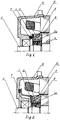
- the device consists of a movable disk-shaped Brake body 1, which is in constant contact with a compression spring 2, which on the Shaft 3 is set and is surrounded from the outside by the short-circuit ring 4a of the rotor 4, where the multi-pole magnetic field conductor 5 is cast.
- a compression spring 2 which on the Shaft 3 is set and is surrounded from the outside by the short-circuit ring 4a of the rotor 4, where the multi-pole magnetic field conductor 5 is cast.
- the brake linings 7 are installed, against which the brake disc 1 lies.
- wave 3 - (Fig. 6) is an approach 3a where the wedge savings 8 are made.
- the disc-shaped brake body 1 (Fig. 3) has two symmetrically located wedge-shaped projections 1a, which are on the same radius as the wedge surfaces on the projection 3a (Fig. 6) lie on the shaft 3 or on the sleeve 3b and fit against each other.
- the proposed second variant of the brake body (Fig. 4) consists of two separately manufactured elements - the disc 1 and the plate-shaped attached to it Body 9 with the end face 9a, which when pressed by the spring on the Brake pad 7 is pressed.
- the plate-shaped body 9 has a larger one Diameter than the bearing seat body, since the brake pad elements 7 on the wall of the End shield 6 are attached.
- the brake body 4 - can be made as one part, like this was mentioned earlier.
- the magnetic field conductor 5 is a conical tooth body, in which the tooth ends 5a are bent so that they lie with their end face 5b close to the rotor assembly 4 and their radial surface 5c is a cylindrical surface with a diameter equal to the diameter of the Form short-circuit rotor 4, this radial surface being in the magnetic field of the stator 10.
- the brake body 1 in the two embodiments (Fig. 1 and Fig. 2) by the magnetic field from the multi-pole Magnetic field conductor 5 attracted and the wedge-shaped projections 1a go easily into the wedge-shaped recesses 8 on the shaft or on the sleeve.
- the compression spring will pressed together and the working surface 9a of the brake body 1 is from the brake pad 7 dressed.
- the electric motor starts to move and works.
- the device according to the invention is not only used for asynchronous Short-circuit motors applied. This device can also be used DC and synchronous motors to be used.
Landscapes
- Engineering & Computer Science (AREA)
- Power Engineering (AREA)
- Braking Arrangements (AREA)
- Connection Of Motors, Electrical Generators, Mechanical Devices, And The Like (AREA)
- Control Of Multiple Motors (AREA)
Abstract
Description
- Fig. 1
- Stellt Längsschnitt der Vorrichtung zum Abbremsen und ein Teil des Asynchronkurzschlußläufermotors, der wobei der Bremskörper als eine Scheibe ausgeführt ist
- Fig. 2
- Längsschnitt der Vorrichtung zum Abbremsen mit Bremskörper, ausgeführt aus zwei festgebundenen Elementen tellerförmigen Körper und Scheibe
- Fig. 3, 3a,3b
- Bremskörper als eine Scheibe ausgeführt
- Fig. 4
- Schnitt des Bremskörpers laut Fig. 2
- Fig. 5 u. 5a
- Beispiel einer Ausführung des mehrpoligen Magnetfeldleiters
- Fig. 6 u. 7
- Läuferwelle
Claims (3)
- Vorrichtung zum Abbremsen von Elektromotoren mit Kurzschlußläufern, bestehend aus einem beweglichen Bremskörper aus weichmagnetischem Werkstoff auf der Welle des Elektromotors mit mindestens zwei keilförmigen Vorsprüngen in Richtung des Läufers, einen Kurzschlußring in welchem ein mehrpoliges Magnetfeldleiter eingegossen ist, wobei zwischen dem Bremskörper und dem Lagerschild des Motors Bremsbeläge eingebaut sind und zwischen dem Bremskörper und dem Läufer im Inneren des Kurzschlußringes eine Druckfeder eingelegt ist, dadurch gekennzeichnet, daß der bewegliche Bremskörper die Form einer Scheibe (1) hat, und daß die im inneren Durchmesser keilförmige Vorsprünge (1a) leicht in die entsprechend keilförmigen Einsparungen (8) auf dem Ansatz der Welle (3) oder auf der Hülse (3b) eingreifen und der mehrpolige Magnetfeldleiter (5) ist konus oder zylinderförmig als Zahnkranz ausgeführt ist, wobei die Zähne so gebogen sind, daß sie mit ihren glattgeformten Fläche (5b) am Läuferpaket dicht anliegen und mit ihren radialen Flächen (5c) unter dem Grundmagnetfeld des Motors liegen, wobei die arbeitenden Stirnfläche (5e) erst dann vorragt, wenn der Kurzschlußring mechanisch durch Drehen fertigbearbeitet ist.
- Die Vorrichtung nach Anspruch 1 ist dadurch gekennzeichnet, daß von der Seite des Bremskörpers (7) zu der Bremsscheibe (1) ein tellerförmiger Körper (9) mit Stirnfläche (9a) festgebunden ist und dicht an dem Bremsbelag von der Feder (2) angedrückt wird.
- Die Vorrichtung nach Anspruch 2 ist dadurch gekennzeichnet, daß der tellerförmige Körper (9) und die Bremsscheibe (1) als ein Teil durch Stanzen oder Tiefziehen aus Blechstahl gefertigt wird.
Applications Claiming Priority (3)
| Application Number | Priority Date | Filing Date | Title |
|---|---|---|---|
| BG961008/75 | 1996-09-30 | ||
| BG100875A BG61889B1 (bg) | 1996-09-30 | 1996-09-30 | Устройство за спиране на електродвигатели |
| BG96100875 | 1996-09-30 |
Publications (2)
| Publication Number | Publication Date |
|---|---|
| EP0833428A1 true EP0833428A1 (de) | 1998-04-01 |
| EP0833428B1 EP0833428B1 (de) | 2003-12-03 |
Family
ID=3926722
Family Applications (1)
| Application Number | Title | Priority Date | Filing Date |
|---|---|---|---|
| EP97116981A Expired - Lifetime EP0833428B1 (de) | 1996-09-30 | 1997-09-30 | Vorrichtung zum Abbremsen von Elektromotoren |
Country Status (4)
| Country | Link |
|---|---|
| EP (1) | EP0833428B1 (de) |
| AT (1) | ATE255783T1 (de) |
| BG (1) | BG61889B1 (de) |
| DE (1) | DE59711068D1 (de) |
Families Citing this family (1)
| Publication number | Priority date | Publication date | Assignee | Title |
|---|---|---|---|---|
| KR101221123B1 (ko) * | 2012-09-28 | 2013-01-10 | 이종석 | 전기브레이크 모터 |
Citations (7)
| Publication number | Priority date | Publication date | Assignee | Title |
|---|---|---|---|---|
| JPS59132750A (ja) * | 1983-01-17 | 1984-07-30 | Fuji Electric Co Ltd | ブレ−キ付回転電機 |
| EP0136282A2 (de) * | 1983-08-31 | 1985-04-03 | AUSTRIA Antriebstechnik G. Bauknecht Aktiengesellschaft | Vorrichtung zum Abbremsen von Elektromotoren |
| DE8716775U1 (de) * | 1987-12-21 | 1988-09-01 | Robert Stahlschmidt Elektromotorenwerk GmbH, 4800 Bielefeld | Käfigläufermotor mit Federdruckbremse |
| DE8912776U1 (de) * | 1989-10-28 | 1990-01-25 | Licentia Patent-Verwaltungs-Gmbh, 6000 Frankfurt | Elektromotor mit beim Abschalten des Motors automatisch wirkender Bremse |
| EP0360779A2 (de) * | 1988-09-21 | 1990-03-28 | AUSTRIA Antriebstechnik G. Bauknecht Aktiengesellschaft | Vorrichtung zum Abbremsen von Elektromotoren |
| DE19503594A1 (de) * | 1994-02-14 | 1995-08-17 | Siemens Ag | Asynchronmotor mit einem Kurzschlußkäfigläufer und einer elektromagnetisch lüftbaren Federdruckbremse |
| DE4423494A1 (de) * | 1994-07-05 | 1996-01-11 | Licentia Gmbh | Elektromotor mit beim Abschalten des Motors automatisch wirkender Bremse |
-
1996
- 1996-09-30 BG BG100875A patent/BG61889B1/bg unknown
-
1997
- 1997-09-30 DE DE59711068T patent/DE59711068D1/de not_active Expired - Fee Related
- 1997-09-30 AT AT97116981T patent/ATE255783T1/de not_active IP Right Cessation
- 1997-09-30 EP EP97116981A patent/EP0833428B1/de not_active Expired - Lifetime
Patent Citations (7)
| Publication number | Priority date | Publication date | Assignee | Title |
|---|---|---|---|---|
| JPS59132750A (ja) * | 1983-01-17 | 1984-07-30 | Fuji Electric Co Ltd | ブレ−キ付回転電機 |
| EP0136282A2 (de) * | 1983-08-31 | 1985-04-03 | AUSTRIA Antriebstechnik G. Bauknecht Aktiengesellschaft | Vorrichtung zum Abbremsen von Elektromotoren |
| DE8716775U1 (de) * | 1987-12-21 | 1988-09-01 | Robert Stahlschmidt Elektromotorenwerk GmbH, 4800 Bielefeld | Käfigläufermotor mit Federdruckbremse |
| EP0360779A2 (de) * | 1988-09-21 | 1990-03-28 | AUSTRIA Antriebstechnik G. Bauknecht Aktiengesellschaft | Vorrichtung zum Abbremsen von Elektromotoren |
| DE8912776U1 (de) * | 1989-10-28 | 1990-01-25 | Licentia Patent-Verwaltungs-Gmbh, 6000 Frankfurt | Elektromotor mit beim Abschalten des Motors automatisch wirkender Bremse |
| DE19503594A1 (de) * | 1994-02-14 | 1995-08-17 | Siemens Ag | Asynchronmotor mit einem Kurzschlußkäfigläufer und einer elektromagnetisch lüftbaren Federdruckbremse |
| DE4423494A1 (de) * | 1994-07-05 | 1996-01-11 | Licentia Gmbh | Elektromotor mit beim Abschalten des Motors automatisch wirkender Bremse |
Non-Patent Citations (1)
| Title |
|---|
| PATENT ABSTRACTS OF JAPAN vol. 8, no. 261 (E - 281)<1698> 30 November 1984 (1984-11-30) * |
Also Published As
| Publication number | Publication date |
|---|---|
| EP0833428B1 (de) | 2003-12-03 |
| BG100875A (en) | 1997-07-31 |
| BG61889B1 (bg) | 1998-08-31 |
| DE59711068D1 (de) | 2004-01-15 |
| ATE255783T1 (de) | 2003-12-15 |
Similar Documents
| Publication | Publication Date | Title |
|---|---|---|
| DE3036091C2 (de) | Elektromotor mit selbsttätig wirkender Bremse | |
| DE19510291C2 (de) | Handwerkzeugmaschine mit Bremseinrichtung | |
| DE102012216588A1 (de) | Kombinierte Fahrzeugbremse | |
| EP1149458A1 (de) | Elektromotor mit elektromagnetischer bremse | |
| EP0136282B2 (de) | Vorrichtung zum Abbremsen von Elektromotoren | |
| EP1008229A1 (de) | Elektromotor | |
| DE19629937C2 (de) | Elektrisch betätigte Kraftfahrzeug-Scheibenbremse, insbesondere in Schwimmsattel-Bauart | |
| DE1114573B (de) | Mit einem Elektromotor zusammengebaute Bremsvorrichtung | |
| EP0833428B1 (de) | Vorrichtung zum Abbremsen von Elektromotoren | |
| DE602004011324T2 (de) | Bremssattel für eine elektromechanische Scheibenbremse | |
| EP1380091B1 (de) | Elektromotor mit bremse | |
| DE4106897C2 (de) | ||
| DE19602895B4 (de) | Werkzeug zur Erzeugung einer Lageranordnung für einen Elektromotor | |
| EP2412082B1 (de) | Elektromotor | |
| DE69603386T2 (de) | Elektromotor mit Ruhestrombremsvorrichtung | |
| DE3935968C2 (de) | Elektromotor mit beim Abschalten des Motors automatisch wirkender Bremse | |
| DE4106914C2 (de) | Elektromotor mit beim Abschalten des Motors selbsttätig wirkender Bremse | |
| WO2013045555A1 (de) | Scheibenbremse für ein nutzfahrzeug | |
| DE8716775U1 (de) | Käfigläufermotor mit Federdruckbremse | |
| EP0209482A2 (de) | Überlastschutzeinrichtung | |
| DE1480686A1 (de) | Fliehkraftkupplung,insbesondere fuer Kraftfahrzeuge | |
| DE3224627C2 (de) | Käfigläufermotor mit einer eingebauten, elektromagnetisch lüftbaren Federdruckbremse | |
| DE3028580A1 (de) | Elektromagnetische federdruckbremse | |
| DE202004007282U1 (de) | Elektromagnetisch gelüftete Zweikreis-Anbaubremse mit ins Lagerschild integrierten Magnetspulen und Druckfederanordnung | |
| DE3214781C2 (de) | Elektromechanisch lüftbare Reibungsbremse |
Legal Events
| Date | Code | Title | Description |
|---|---|---|---|
| PUAI | Public reference made under article 153(3) epc to a published international application that has entered the european phase |
Free format text: ORIGINAL CODE: 0009012 |
|
| AK | Designated contracting states |
Kind code of ref document: A1 Designated state(s): AT DE FR IT |
|
| 17P | Request for examination filed |
Effective date: 19980909 |
|
| AKX | Designation fees paid |
Free format text: AT DE FR IT |
|
| RBV | Designated contracting states (corrected) |
Designated state(s): AT DE FR IT |
|
| 17Q | First examination report despatched |
Effective date: 20000614 |
|
| GRAH | Despatch of communication of intention to grant a patent |
Free format text: ORIGINAL CODE: EPIDOS IGRA |
|
| GRAS | Grant fee paid |
Free format text: ORIGINAL CODE: EPIDOSNIGR3 |
|
| GRAA | (expected) grant |
Free format text: ORIGINAL CODE: 0009210 |
|
| AK | Designated contracting states |
Kind code of ref document: B1 Designated state(s): AT DE FR IT |
|
| REF | Corresponds to: |
Ref document number: 59711068 Country of ref document: DE Date of ref document: 20040115 Kind code of ref document: P |
|
| ET | Fr: translation filed | ||
| PGFP | Annual fee paid to national office [announced via postgrant information from national office to epo] |
Ref country code: FR Payment date: 20040826 Year of fee payment: 8 |
|
| PGFP | Annual fee paid to national office [announced via postgrant information from national office to epo] |
Ref country code: AT Payment date: 20040830 Year of fee payment: 8 |
|
| PGFP | Annual fee paid to national office [announced via postgrant information from national office to epo] |
Ref country code: DE Payment date: 20040929 Year of fee payment: 8 |
|
| PLBE | No opposition filed within time limit |
Free format text: ORIGINAL CODE: 0009261 |
|
| STAA | Information on the status of an ep patent application or granted ep patent |
Free format text: STATUS: NO OPPOSITION FILED WITHIN TIME LIMIT |
|
| 26N | No opposition filed |
Effective date: 20040906 |
|
| PG25 | Lapsed in a contracting state [announced via postgrant information from national office to epo] |
Ref country code: IT Free format text: LAPSE BECAUSE OF NON-PAYMENT OF DUE FEES;WARNING: LAPSES OF ITALIAN PATENTS WITH EFFECTIVE DATE BEFORE 2007 MAY HAVE OCCURRED AT ANY TIME BEFORE 2007. THE CORRECT EFFECTIVE DATE MAY BE DIFFERENT FROM THE ONE RECORDED. Effective date: 20050930 Ref country code: AT Free format text: LAPSE BECAUSE OF NON-PAYMENT OF DUE FEES Effective date: 20050930 |
|
| PG25 | Lapsed in a contracting state [announced via postgrant information from national office to epo] |
Ref country code: DE Free format text: LAPSE BECAUSE OF NON-PAYMENT OF DUE FEES Effective date: 20060401 |
|
| PG25 | Lapsed in a contracting state [announced via postgrant information from national office to epo] |
Ref country code: FR Free format text: LAPSE BECAUSE OF NON-PAYMENT OF DUE FEES Effective date: 20060531 |
|
| REG | Reference to a national code |
Ref country code: FR Ref legal event code: ST Effective date: 20060531 |