EP0833697B1 - Pipe coating apparatus - Google Patents
Pipe coating apparatus Download PDFInfo
- Publication number
- EP0833697B1 EP0833697B1 EP96917603A EP96917603A EP0833697B1 EP 0833697 B1 EP0833697 B1 EP 0833697B1 EP 96917603 A EP96917603 A EP 96917603A EP 96917603 A EP96917603 A EP 96917603A EP 0833697 B1 EP0833697 B1 EP 0833697B1
- Authority
- EP
- European Patent Office
- Prior art keywords
- pipe
- coating
- coating station
- booth
- station
- Prior art date
- Legal status (The legal status is an assumption and is not a legal conclusion. Google has not performed a legal analysis and makes no representation as to the accuracy of the status listed.)
- Expired - Lifetime
Links
Images



Classifications
-
- B—PERFORMING OPERATIONS; TRANSPORTING
- B05—SPRAYING OR ATOMISING IN GENERAL; APPLYING FLUENT MATERIALS TO SURFACES, IN GENERAL
- B05B—SPRAYING APPARATUS; ATOMISING APPARATUS; NOZZLES
- B05B13/00—Machines or plants for applying liquids or other fluent materials to surfaces of objects or other work by spraying, not covered by groups B05B1/00 - B05B11/00
- B05B13/02—Means for supporting work; Arrangement or mounting of spray heads; Adaptation or arrangement of means for feeding work
- B05B13/0207—Means for supporting work; Arrangement or mounting of spray heads; Adaptation or arrangement of means for feeding work the work being an elongated body, e.g. wire or pipe
-
- B—PERFORMING OPERATIONS; TRANSPORTING
- B28—WORKING CEMENT, CLAY, OR STONE
- B28B—SHAPING CLAY OR OTHER CERAMIC COMPOSITIONS; SHAPING SLAG; SHAPING MIXTURES CONTAINING CEMENTITIOUS MATERIAL, e.g. PLASTER
- B28B21/00—Methods or machines specially adapted for the production of tubular articles
- B28B21/92—Methods or apparatus for treating or reshaping
- B28B21/94—Methods or apparatus for treating or reshaping for impregnating or coating by applying liquids or semi-liquids
Definitions
- This invention is concerned with the coating of pipes of the type used in subterranean or submerged pipelines for the recovery of oil, gas, slurries or like pipeable materials from a subterranean well.
- it is concerned with pipes in which a steel pipe section is covered with a bituminous-type anticorrosion coating.
- each pipe is lifted, e.g. by overhead crane, on to conveyor means for individual coating treatment.
- the conveyor means causes each pipe to rotate about its longitudinal axis while it is passed longitudinally past different treatment stations.
- the pipes are pre-heated to remove all moisture before being shot blast cleaned to remove all dirt and foreign matter in order to ensure an optimum coating-to-pipe bond.
- a primer is then applied by a measured spray.
- a bituminous-type coating usually asphalt or coal tar, is poured as a flood coat over the rotating pipe.
- a glass fibre inner wrap followed by an asbestos felt, glass fibre or glass cloth outer wrap can be simultaneously wound on to the pipe during the coating process.
- whitewash or a similar solar protection agent is then applied to the coated pipe to prevent adhesion between adjacent pipes and to minimise the effects of direct sunlight upon the integrity of the coating.
- Pipes coated thus and reinforced with the necessary glass fibre inner wraps and felt or glass outer wraps provide adequate protection for normal in line temperatures of up to 80°C (coal tar) or 70°C (asphalt) maximum for oil, gas or water lines.
- US-A-2 133 014 proposes a bitumen applicator with a controllable shut-off to enable termination of the coating transversely whereby an annular band of uncoated pipe surface remains, and further proposes that beneath the applicator there is a drip catch device with optional recycle pump.
- Pipes to be coated are connected by coupling connectors and the connected pipes are passed through for coating from dollies on a feed-in track terminating before the applicator on to similar dollies on a take-off track placed just after the applicator. In this way sequential pipes provide mutual support during coating via their connectors without having to pass a support dolly under the applicator during the coating step.
- An object of the present invention is to provide improvements in the coating of pipes, and generally obviate or mitigate the problems of known commercial coating processes.
- the invention to be more particularly described hereinafter addresses these problems by providing apparatus for coating of pipes including unique pipe handling means adapted to contact a pipe at predetermined times and in a predetermined manner permitting each pipe to be progressively advanced through the coating booth without the integrity of the applied coating being compromised by the pipe handling means and thereby minimising the risk of the handling apparatus being fouled by coating spillage.
- said handling means includes a pipe feed mechanism for introducing a pipe lengthwise in the direction of its longitudinal axis to the coating booth whilst simultaneously applying an appropriate degree of rotation about that longitudinal axis, which mechanism has a pipe hold-down feature whereby the leading end of the pipe is permitted to project freely into the booth whilst another part of the pipe is restrained to avoid the pipe toppling into the booth due to lack of support at the leading end, and said handling means further includes at least first and second pipe end supports for picking up the coated pipe as it exits the coating booth.
- the first and second pipe end supports are provided on remote controlled vehicles which are preferably rail guided, and independently operable to convey respectively the leading and trailing ends of the pipe as it emerges from the coating booth.
- the pipe enters the booth as an unsupported overhang which is readily flood or curtain coated since no support mechanism can interfere with the application of the coating.
- the remote or trailing end of the pipe which has not yet entered the booth is subject to a "hold down" to stabilise the pipe delivery for coating purposes.
- a first end support device is activated to contact the leading end of the pipe and convey it on a remotely.controlled vehicle away from the booth.
- a second support device is activated to contact the trailing end of the pipe and convey it on a second vehicle away from the coating booth.
- first and second vehicles are synchronised such that they operate in tandem and contact the pipe surface only near the ends of the pipe so that again there is minimum risk of contact or interference with the applied coating.
- the said vehicles are shuttled back and forth in a repeatable cycle which can be appropriately timed and coordinated with downstream pipe conveying or offloading devices to permit both vehicles to be returned for pipe end pick up whilst the next pipe in turn is entering the booth and undergoing coating.
- the invention permits an essentially continual and generally uninterrupted coating operation to be operated.
- the remotely operable support devices may include arms which may be rapidly deployed from a stand off position to a pipe contacting position by pivoting, swinging, sliding or like action.
- a pipe conveyor whose final point of delivery is just short of a flood or curtain coating device provided within a coating station.
- a pair of parallel rails extends away from coating station to a pipe offloading area.
- Mobile carriers positioned on the rails adjacent to the coating station, stand ready to receive a coated pipe emerging from the coating station. Once coated, the pipe is conveyed away from the coating station firstly by one such carrier engaging the leading end of the emerging coated pipe and subsequently on other carrier cooperating in tandem with the first to support the trailing end of the pipe. The pipe would then be collected from the mobile carriers which are returned to their initial position ready to receive another pipe.
- the collection device may be a hoist, overhead gantry mounted crane, or other suitable lifting device adapted to minimise the risk of damage to the pipe coating.
- the carriers themselves are provided with offloading lever mechanisms whereby the pipe may be laterally displaced from the carriers onto a storage facility or conveyor device.
- the mobile carrier pipe supports are idler rollers mounted on hinged support arms. Said arms are curved in shape such that, when not held in contact with the pipe they may be positioned so as not to impede either the flow of coating material applied to the surface of the pipe, or the flow of excess coating material from the undersurface of the pipe.
- a method of coating a series of pipes in a flood or curtain coating station comprising the steps of providing a pipe conveyor whose final point of delivery is just short of a flood or curtain coating device provided within said coating station, conveying a pipe in the direction of its longitudinal axis whilst rotating it about that axis and causing the one end of the pipe to project under the flood or curtain coating device whilst holding down a remote part of the pipe, by such means as an overhead clamp adapted to make contact with the pipe by provision of roller devices, to stabilise the pipe, conveying the pipe further into the coating station by means of said conveyor and applying a coating by means of said coating device to coat said pipe, providing a plurality of mobile pipe carriers provided with deployable pipe supports and control means to operate a first and a second pipe carrier in a synchronised sequence related to the passage of the pipe through the coating station, actuating the first pipe carrier to provide support for the pipe as the pipe begins to emerge from the coating station, and after a predetermined time delay actu
- Coating apparatus 5 provided by this invention includes a static conveyor 10 for transporting pipes 15, 15' in series to the entrance of a coating delivery station 20 whilst rotating them about their longitudinal axis.
- Mobile pipe carriers 25, 25' initially positioned adjacent to the static conveyor 10, are supported on rails 30. Said rails 30 lead from the static conveyor 10, past the coating delivery station, to a pipe unloading area 35 .
- a collection pan 40 is provided below the delivery station 20 to collect any coating material which fails to adhere to the pipes.
- the leading portion 45 of pipe 15 is passed by the static conveyor 10 to the leading pipe carrier 25.
- Said leading pipe carrier is provided with a drive unit 50 with which to engage the leading portion 45 and maintain the rotation imparted to the pipe 15 by the static conveyor 10. Coating material is applied to the rotating pipe 15 as it passes the coating delivery station 20.
- the static conveyor 10 is provided with a hold down unit 55 (in the form of an overhead clamp adapted to make contact with the pipe by provision of means of roller devices) to prevent the leading portion 45 of the pipe 15 from pivoting downwards before it reaches the leading pipe carrier 25.
- the leading pipe carrier 25 advances along the rails 30 and thus continues to move the pipe 15 past the coating delivery station 20.
- the trailing portion 45' of the pipe 15 approaches the end of the static conveyor 10 it is supported by rollers 60 mounted on the trailing pipe carrier 25', thus allowing the pipe 15 to continue to rotate under the influence of the drive unit 50.
- the trailing pipe carrier 25' has received the trailing portion 45' of the pipe 15, it too advances along the rails 30 at substantially the same speed as the leading pipe carrier 25.
- the two carriers 25, 25' transport the rotating pipe 15 to the unloading area 35, whereupon it is ejected from the carriers 25, 25' by lever units 65 and 65'.
- the empty carriers 25, 25' then return along the rails 30 to their original positions ready to receive the next pipe 15' from the static conveyor 10.
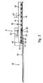
- a pipe carrier 25 (shown in Fig. 5) comprises a wheeled chassis 70 surmounted by a drive unit 50, driven support rollers 75 which serve to connect the drive unit 50 to the pipe 15, and a lever unit 65 to eject the pipe 15 from the carrier 25.
- the lever unit 65 is composed of a concave load bearing surface 80 connected to a support frame 85 by pins 90 , the support frame 85 being attached in turn to the chassis 70.
- a hydraulic ram 95 is mounted between the load bearing surface 80 and the chassis 70. Extension of the ram 95 causes the load bearing surface 80 to rotate about the pins 90 and come into contact with the pipe 15 and, with further extension, tip the pipe 15 from the carrier 25.
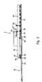
- a trailing pipe carrier 25' comprising a wheeled chassis 100, a lever unit 65' and a pair of support arms 105.
- Said chassis 100 straddles the collection pan 40 when the carrier 25' is in its initial position adjacent to the static conveyor. Hence, during the coating operation, excess coating material may flow unimpeded from the undersurface of the pipe to the collection pan 40.
- Support arms 105 are connected by pins 110 to the chassis 100, and are surmounted by rollers 60. The arms 105 can be rotated about the pins 110 by the action of hydraulic rams 115 positioned between the arms 105 and the chassis 100. This enables the rollers 60 to be moved into and out of contact with the pipe 15 as shown in Figure 7.
- the arms 105 and rollers 60 are only moved into contact with the pipe 15, in order to support it, as the trailing portion 45' approaches the end of the static conveyor 10. In this way the rollers 60 do not impede the passage of the majority of the pipe 15 past the coating delivery station. Furthermore, when not in contact with the pipe 15 the rollers 60 and arms 105 may be held in a position remote from the flow of coating material.
- the first carrier may be actuated by contact with the pipe emerging from the coating station so that drive means for advancing the first carrier is not essential since forward motion is still being imparted to the pipe by the conveyor on the other side of the coating station. Obviously once the pipe leaves the conveyor the second carrier would need to be driven to continue the progression of the pipe out of the coating station.
- the specific drive mechanisms may be operated by a variety of systems as known in this art for other purposes.
- the carriers themselves need not be rail guided vehicles but could be soft tyred or track-laying vehicles. It will be recognised that the invention as herein disclosed provides a simple and relatively easily constructed solution to long-standing problems experienced in this art.
Landscapes
- Engineering & Computer Science (AREA)
- Manufacturing & Machinery (AREA)
- Chemical & Material Sciences (AREA)
- Ceramic Engineering (AREA)
- Mechanical Engineering (AREA)
- Coating Apparatus (AREA)
- Application Of Or Painting With Fluid Materials (AREA)
- Spray Control Apparatus (AREA)
Applications Claiming Priority (3)
| Application Number | Priority Date | Filing Date | Title |
|---|---|---|---|
| GBGB9512499.6A GB9512499D0 (en) | 1995-06-20 | 1995-06-20 | Pipe coating apparatus |
| GB9512499 | 1995-06-20 | ||
| PCT/GB1996/001418 WO1997000733A1 (en) | 1995-06-20 | 1996-06-17 | Pipe coating apparatus |
Publications (2)
| Publication Number | Publication Date |
|---|---|
| EP0833697A1 EP0833697A1 (en) | 1998-04-08 |
| EP0833697B1 true EP0833697B1 (en) | 2002-08-14 |
Family
ID=10776339
Family Applications (1)
| Application Number | Title | Priority Date | Filing Date |
|---|---|---|---|
| EP96917603A Expired - Lifetime EP0833697B1 (en) | 1995-06-20 | 1996-06-17 | Pipe coating apparatus |
Country Status (5)
| Country | Link |
|---|---|
| EP (1) | EP0833697B1 (da) |
| DK (1) | DK0833697T3 (da) |
| GB (1) | GB9512499D0 (da) |
| NO (1) | NO326712B1 (da) |
| WO (1) | WO1997000733A1 (da) |
Families Citing this family (6)
| Publication number | Priority date | Publication date | Assignee | Title |
|---|---|---|---|---|
| CN102974489A (zh) * | 2011-09-05 | 2013-03-20 | 吕林果 | 一种自动化钢管喷漆机 |
| KR101858814B1 (ko) * | 2016-07-12 | 2018-05-17 | 두산중공업 주식회사 | 응축기 전열관 코팅 시스템 |
| US10738560B2 (en) * | 2017-04-25 | 2020-08-11 | Baker Hughes, A Ge Company, Llc | Packers having controlled swelling and methods of manufacturing thereof |
| CN107971171A (zh) * | 2017-09-30 | 2018-05-01 | 科澳特石油工程技术有限公司 | 石油管道外涂油设备 |
| CN111037738B (zh) * | 2019-12-31 | 2025-03-18 | 青铜峡市青龙新型管材有限公司 | 一种钢筋混凝土管自动抹面装置 |
| CN116550694B (zh) * | 2023-07-10 | 2023-09-29 | 山东蓝色海洋科技股份有限公司 | 一种风电塔外壁防腐处理用清洁装置 |
Family Cites Families (8)
| Publication number | Priority date | Publication date | Assignee | Title |
|---|---|---|---|---|
| US1883964A (en) * | 1929-09-03 | 1932-10-25 | Gen Paint Corp | Dolly and return trackway |
| US2133014A (en) * | 1936-10-28 | 1938-10-11 | Gen Paint Corp | Pipe coating apparatus |
| US2279340A (en) * | 1938-12-05 | 1942-04-14 | Standard Oil Co California | Conveyer for coated pipe |
| US2602415A (en) * | 1950-01-16 | 1952-07-08 | Wayne C Hall | Machine for applying protective coating to pipes |
| US2625905A (en) * | 1950-04-13 | 1953-01-20 | Rosson Richards Proc Co Inc | Apparatus for applying coating material to pipe |
| US3041700A (en) * | 1960-04-25 | 1962-07-03 | Carl K Smith | Apparatus for coating pipes |
| DE3712422C1 (de) * | 1987-04-10 | 1988-08-04 | Mannesmann Ag | Verfahren und Vorrichtung zum Auftragen eines fluessigen Behandlungsmittels auf Stahlrohre |
| GB9323725D0 (en) * | 1993-11-17 | 1994-01-05 | Bredero Price Services | Pipe coating apparatus |
-
1995
- 1995-06-20 GB GBGB9512499.6A patent/GB9512499D0/en active Pending
-
1996
- 1996-06-17 EP EP96917603A patent/EP0833697B1/en not_active Expired - Lifetime
- 1996-06-17 DK DK96917603T patent/DK0833697T3/da active
- 1996-06-17 WO PCT/GB1996/001418 patent/WO1997000733A1/en not_active Ceased
-
1997
- 1997-12-22 NO NO19976050A patent/NO326712B1/no not_active IP Right Cessation
Also Published As
| Publication number | Publication date |
|---|---|
| WO1997000733A1 (en) | 1997-01-09 |
| EP0833697A1 (en) | 1998-04-08 |
| NO976050L (no) | 1998-02-20 |
| NO976050D0 (no) | 1997-12-22 |
| DK0833697T3 (da) | 2002-10-07 |
| GB9512499D0 (en) | 1995-08-23 |
| NO326712B1 (no) | 2009-02-02 |
Similar Documents
| Publication | Publication Date | Title |
|---|---|---|
| CN201293182Y (zh) | 管道防腐层一体化补口机 | |
| WO1997000733A1 (en) | Pipe coating apparatus | |
| CN107866352A (zh) | 一种刹车片涂胶流水线 | |
| CN208717169U (zh) | 一种多层玻璃自动贴合装置 | |
| CN219664090U (zh) | 一种板材底板涂油设备 | |
| US6270847B1 (en) | Method of cooling coated pipe | |
| US3687704A (en) | Method for coating pipe | |
| EP0826433A3 (de) | Verfahren und Vorrichtung zur Innenbeschichtung einer Gasflasche | |
| US3120460A (en) | Figure | |
| US5343930A (en) | Centrifugal casting system having a carrier of elongated materials | |
| US2291823A (en) | Pipe coating machine | |
| CN115417199B (zh) | 一种熔喷吸油材料制备装置及其制备方法 | |
| US3894637A (en) | Apparatus for handling pipe joints coated with mastic material | |
| CN111703093A (zh) | 一种用于pe管材加工的系统 | |
| CN215964410U (zh) | 一种防粘贴型纸制品制作装置 | |
| AU668475B2 (en) | Shuttlecar unloading device | |
| EP0729403A1 (en) | Pipe coating apparatus | |
| CN115806213B (zh) | 一种气凝胶检测设备 | |
| CN112774906A (zh) | 一种工业铝型材自动喷涂装置 | |
| JPH11319655A (ja) | 小物部材の塗装ライン設備 | |
| CN108233290B (zh) | 一种pe管材加工系统 | |
| CN218531418U (zh) | 一种小桶喷漆生产装置 | |
| CN210304188U (zh) | 一种钢管接箍均匀喷漆的设备 | |
| EP0179596A2 (en) | Plant for coating pipe, tubing and the like | |
| CN214191828U (zh) | 一种应用于输送带的自动上浆机构 |
Legal Events
| Date | Code | Title | Description |
|---|---|---|---|
| PUAI | Public reference made under article 153(3) epc to a published international application that has entered the european phase |
Free format text: ORIGINAL CODE: 0009012 |
|
| 17P | Request for examination filed |
Effective date: 19980119 |
|
| AK | Designated contracting states |
Kind code of ref document: A1 Designated state(s): DK FR GB IT NL |
|
| 17Q | First examination report despatched |
Effective date: 19990428 |
|
| RAP1 | Party data changed (applicant data changed or rights of an application transferred) |
Owner name: BREDERO PRICE COATERS LIMITED |
|
| GRAG | Despatch of communication of intention to grant |
Free format text: ORIGINAL CODE: EPIDOS AGRA |
|
| GRAG | Despatch of communication of intention to grant |
Free format text: ORIGINAL CODE: EPIDOS AGRA |
|
| GRAH | Despatch of communication of intention to grant a patent |
Free format text: ORIGINAL CODE: EPIDOS IGRA |
|
| GRAH | Despatch of communication of intention to grant a patent |
Free format text: ORIGINAL CODE: EPIDOS IGRA |
|
| GRAA | (expected) grant |
Free format text: ORIGINAL CODE: 0009210 |
|
| AK | Designated contracting states |
Kind code of ref document: B1 Designated state(s): DK FR GB IT NL |
|
| REG | Reference to a national code |
Ref country code: GB Ref legal event code: FG4D |
|
| REG | Reference to a national code |
Ref country code: DK Ref legal event code: T3 |
|
| ET | Fr: translation filed | ||
| PLBE | No opposition filed within time limit |
Free format text: ORIGINAL CODE: 0009261 |
|
| STAA | Information on the status of an ep patent application or granted ep patent |
Free format text: STATUS: NO OPPOSITION FILED WITHIN TIME LIMIT |
|
| 26N | No opposition filed |
Effective date: 20030515 |
|
| NLS | Nl: assignments of ep-patents |
Owner name: SHAWCOR LTD. Effective date: 20080617 |
|
| REG | Reference to a national code |
Ref country code: GB Ref legal event code: 732E |
|
| REG | Reference to a national code |
Ref country code: FR Ref legal event code: TP |
|
| PG25 | Lapsed in a contracting state [announced via postgrant information from national office to epo] |
Ref country code: IT Free format text: LAPSE BECAUSE OF NON-PAYMENT OF DUE FEES Effective date: 20090617 |
|
| PGRI | Patent reinstated in contracting state [announced from national office to epo] |
Ref country code: IT Effective date: 20110616 |
|
| REG | Reference to a national code |
Ref country code: FR Ref legal event code: PLFP Year of fee payment: 20 |
|
| PGFP | Annual fee paid to national office [announced via postgrant information from national office to epo] |
Ref country code: DK Payment date: 20150625 Year of fee payment: 20 Ref country code: GB Payment date: 20150630 Year of fee payment: 20 |
|
| PGFP | Annual fee paid to national office [announced via postgrant information from national office to epo] |
Ref country code: NL Payment date: 20150623 Year of fee payment: 20 |
|
| PGFP | Annual fee paid to national office [announced via postgrant information from national office to epo] |
Ref country code: FR Payment date: 20150630 Year of fee payment: 20 |
|
| PGFP | Annual fee paid to national office [announced via postgrant information from national office to epo] |
Ref country code: IT Payment date: 20150625 Year of fee payment: 20 |
|
| REG | Reference to a national code |
Ref country code: DK Ref legal event code: EUP Effective date: 20160617 |
|
| REG | Reference to a national code |
Ref country code: NL Ref legal event code: MK Effective date: 20160616 |
|
| REG | Reference to a national code |
Ref country code: GB Ref legal event code: PE20 Expiry date: 20160616 |
|
| PG25 | Lapsed in a contracting state [announced via postgrant information from national office to epo] |
Ref country code: GB Free format text: LAPSE BECAUSE OF EXPIRATION OF PROTECTION Effective date: 20160616 |