EP0833716B1 - Kühlsystem mit gasstrahlmesser - Google Patents
Kühlsystem mit gasstrahlmesser Download PDFInfo
- Publication number
- EP0833716B1 EP0833716B1 EP96913413A EP96913413A EP0833716B1 EP 0833716 B1 EP0833716 B1 EP 0833716B1 EP 96913413 A EP96913413 A EP 96913413A EP 96913413 A EP96913413 A EP 96913413A EP 0833716 B1 EP0833716 B1 EP 0833716B1
- Authority
- EP
- European Patent Office
- Prior art keywords
- gas
- cooling
- soldered products
- soldered
- flux
- Prior art date
- Legal status (The legal status is an assumption and is not a legal conclusion. Google has not performed a legal analysis and makes no representation as to the accuracy of the status listed.)
- Expired - Lifetime
Links
Images
Classifications
-
- B—PERFORMING OPERATIONS; TRANSPORTING
- B23—MACHINE TOOLS; METAL-WORKING NOT OTHERWISE PROVIDED FOR
- B23K—SOLDERING OR UNSOLDERING; WELDING; CLADDING OR PLATING BY SOLDERING OR WELDING; CUTTING BY APPLYING HEAT LOCALLY, e.g. FLAME CUTTING; WORKING BY LASER BEAM
- B23K1/00—Soldering, e.g. brazing, or unsoldering
- B23K1/008—Soldering within a furnace
-
- B—PERFORMING OPERATIONS; TRANSPORTING
- B23—MACHINE TOOLS; METAL-WORKING NOT OTHERWISE PROVIDED FOR
- B23K—SOLDERING OR UNSOLDERING; WELDING; CLADDING OR PLATING BY SOLDERING OR WELDING; CUTTING BY APPLYING HEAT LOCALLY, e.g. FLAME CUTTING; WORKING BY LASER BEAM
- B23K3/00—Tools, devices or special appurtenances for soldering, e.g. brazing, or unsoldering, not specially adapted for particular methods
- B23K3/08—Auxiliary devices therefor
- B23K3/085—Cooling, heat sink or heat shielding means
-
- B—PERFORMING OPERATIONS; TRANSPORTING
- B23—MACHINE TOOLS; METAL-WORKING NOT OTHERWISE PROVIDED FOR
- B23K—SOLDERING OR UNSOLDERING; WELDING; CLADDING OR PLATING BY SOLDERING OR WELDING; CUTTING BY APPLYING HEAT LOCALLY, e.g. FLAME CUTTING; WORKING BY LASER BEAM
- B23K3/00—Tools, devices or special appurtenances for soldering, e.g. brazing, or unsoldering, not specially adapted for particular methods
- B23K3/08—Auxiliary devices therefor
-
- B—PERFORMING OPERATIONS; TRANSPORTING
- B23—MACHINE TOOLS; METAL-WORKING NOT OTHERWISE PROVIDED FOR
- B23K—SOLDERING OR UNSOLDERING; WELDING; CLADDING OR PLATING BY SOLDERING OR WELDING; CUTTING BY APPLYING HEAT LOCALLY, e.g. FLAME CUTTING; WORKING BY LASER BEAM
- B23K2101/00—Articles made by soldering, welding or cutting
- B23K2101/36—Electric or electronic devices
- B23K2101/40—Semiconductor devices
Definitions
- the present invention relates to reflow soldering and more specifically to a method of cooling soldered articles immediately after soldering.
- Printed circuit board assemblies are cooled after reflow soldering to reduce the temperature of the soldered articles below the melting temperature of the solder.
- the articles to be soldered are first covered with a solder paste containing flux which is then heated in at least one heat zone so that the solder melts and the flux liquifies permitting the solder to flow and cover the joint or area to be soldered.
- the soldered articles pass into a cooling section where the solder is cooled below the melting temperature, thus hardening the solder on the circuit board assemblies. In most cases there is also some liquid or solid flux deposits on the solder which forms in the cooler section.
- U.S. Patent 5,125,556 to Deambrosio discloses one example of a cooling unit for a reflow soldering system
- U.S. Patent 4,912,857 to Parent et al discloses one example of a reflow soldering apparatus
- the cooling unit is generally a separate section and incorporates moving ambient gas via fans or blowers through a heat exchanger.
- the recirculation of the ambient gas can cause problems with regard to flux deposits in the heat exchangers and within the flow actuators. These deposits can cause clogging of the heat exchangers and flow actuators which can degrade the cooling performance over time. This results in increased maintenance and down time.
- a further reflow soldering apparatus and method are described in US Patent 5,345,061 to Chanasyk et al (on which the pre-characterising part of claim 1 is based).
- a component to be soldered is transported by a conveyor belt through a plurality of identically configured zones.
- gas is directed through holes in a plate towards the component.
- the plates are heated so as to heat gas passing therethrough and consequently heat the component for soldering purposes.
- the plate in the last zone is not heated however so that gas directed at the component therein cools the component.
- the plate in the last zone is heatable to provide flexibility in the manner in which the apparatus is operated.
- Another suggested scheme is a cleaning cycle for the entire reflow apparatus.
- the heating zones and the cooling zones are heated to a temperature which allows flux deposits within the oven to vaporize.
- Such a procedure has a number of problems, one of them being due to the large thermal mass of the heating zones requiring high heating energy which is both costly and time consuming.
- There is a three step process which heats up, bakes out and cools down the complete apparatus. This requires the shut down of the reflow apparatus.
- Another problem is that the recirculating coolant must be entirely purged from the heat exchanger used in the cooling zone, otherwise it may rupture as a result of high pressure at elevated cleaning temperatures. This last point is of concern because a failure of the purge system could result in personal injury.
- a high circulation of ambient gas passes through a heat exchanger to cool the gas.
- the soldered articles are then conveyed through the cooled gas.
- the two most common gases used in this cooling system are air and nitrogen. Nitrogen provides an inert process environment and much brighter solder joints are obtained in a nitrogen atmosphere as oxidation does not occur on the surface of the solder.
- a method of cooling soldered products passing on a conveyor from a heating section of a reflow soldering apparatus to a cooling section comprising the steps of:
- gas knife used herein refers to any device that provides a suitable gas stream, or an impinging flow cooling system to cool an object. Gas knife should be considered as a gas flow actuator such as slot nozzles, round nozzles or arrays of nozzles positioned to provide an impinging gas flow.
- a system for operating in accordance with the inventive method may comprise a gas knife cooling system for a reflow soldering apparatus having a heating section followed by a cooling section, with a conveyor for carrying products to be soldered through the apparatus, the gas knife cooling system comprising at least one gas knife in the cooling section positioned to direct a gas stream at soldered products on the conveyor to cool the products, and including a heater associated with the gas knife activated for predetermined cleaning cycles to heat the gas knife to a temperature above flux vaporization temperature of flux deposits from the soldered products.
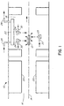
- a reflow soldering apparatus 10 is shown in Figure 1 wherein a printed circuit board assembly 12 or other article to be soldered is conveyed on a conveyor 14 through a heating section 16 to a cooking section 18.
- Infrared heaters 20 are shown in the heating section 16, however, these heaters are but one type of heater used in a reflow soldering apparatus.
- Heated gas forced convection systems may be used, or any other suitable heating system that heats the articles 12 passing on the conveyor 14 through the heating section 16.
- a heat exchanger 22 is mounted above a plurality of upper gas knives 24 which direct gas streams onto the top of the soldered articles 12 passing on the conveyor 14.
- a lower gas knife 25 is shown positioned below the conveyor 14 so that a gas stream is directed onto the underside of the soldered articles 12.
- the heat exchanger 22 cools and stabilizes the ambient temperature of the gas in the cooling section 18. This stabilization is desirable when there is heavy product loading through the cooling section 18.
- Each of the soldered articles 12 is cooled giving up heat which is dissipated in the cooling section 18.
- a separate cooling system provides a circulated coolant which may be air or other gas, water or water/glycol mixture, or other coolant mixtures, to pass through entry 26 into the heat exchanger 22 and out through exit 28.
- the heat exchanger may utilize convective cooling with heat dissipation fins or electronic cooling or other suitable cooling means.
- a heat exchanger 22 may be located under the lower gas knife 25, beneath the conveyor 14, or outside the cooling section altogether. The heat exchanger cooling system is quite separate to the gas streams from the gas knives 24,25. In certain applications a heat exchanger 22 is not required.
- the gas knives 24,25 are producing a directed gas stream rather than the more typical gas circulation systems utilizing blowers, the problem of condensation or clogging of the heat exchanger 22 with flux deposits does not occur because the process gases do not circulate therethrough.
- the gas flow to the gas knives 24,25 is from a separate source and is generally not recirculated.
- the source of compressed gas may be an air compressor, compressed bottle gas, a nitrogen tank or other suitable source.
- the gas is delivered approximately at room temperature or slightly below, therefore is not cooled before passing through the gas entry line 30 to the gas knives 24,25.
- the gas knife 24 has an electric heater 32 positioned at the back thereof to heat the gas knife 24. There is also some heating of the gas passing through the gas knife 24.
- the temperature of the gas knives 24,25 for a cleaning cycle must be above the vaporizing temperature of the flux, thus the flux deposits vaporize and this prevents a build up of flux deposits on the gas knives 24,25.
- the cleaning cycle occurs for a sufficient time to vaporize the flux residues, thus the maintenance of the cooling section is far simpler than in the existing types of cooling sections for reflow solder devices where an extensive heat cycle is necessary to remove flux deposits.
- the vaporised flux deposits generally exit from exhausts at each end of the soldering apparatus 10. Because the gas supplied to the gas knives 24,25 is from a separate source, there is a continuous flow of gas out of the cooling section 18. This continuous gas flow evacuates the flux vapour in part which allows it to be removed from the system by the exhausts at the end of the soldering apparatus 10. Some flux vapour may condense on the walls of the soldering apparatus and some may also re-condense on the gas knives 24,25. However, because the surface area of the gas knives is small compared to the overall surface area of the apparatus, there is only a slight build up of flux deposits.
- the number and location of gas knives 24,25 are determined by the amount of heat transfer desired.
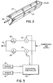
- the gas knives are fed gas through a flow controller as shown in Figure 3.
- At least one gas knife has a thermocouple 33 referred to as the temperature sensor in Figure 3.
- the thermocouple 33 provides a closed loop control of the heater.
- the purpose of the heat exchanger is to maintain the required temperature in the cooling section.
- cool gas from an exterior source is directed from the gas knives 24,25 at the soldered articles 12.
- the flow of gas through the gas knives is reduced compared to a normal conventional cooling section.
- Figure 3 illustrates a controller arrangement for controlling the gas flow for normal process cooling and for a cleaning cycle.
- the gas supply passes through a first valve 34 which is open, a reducing valve 36, and then enters the gas knives 24,25 through line 30.
- the second valve 38 which provides a second gas supply, is closed during normal cooling.
- the first valve 34 is closed and the second valve 38 is open, the compressed gas supply passes through a second reducing valve 40 which permits a reduced gas flow for the cleaning cycle as compared to the normal process cooling flow.
- the controller 42 also activates the heaters 32 in the gas knives 24,25, the temperature of the heater 32 is controlled by the thermocouple 33.
- the heater 32 heats the gas knives 24,25 above the vaporization temperature of the flux so the flux deposits on the gas knives vaporize.
- the gas flow per knife is preferably in the range from 2.83 m 3 /hr to 70.8 m 3 /hr (100 to 2500 ft 3 /hr) at an input pressure of 207 kPa - 827 kPa (30 to 120 psi).
- Nitrogen is the preferred gas although other types of suitable gases may be used.
- air may be circulated in the cooling section.
- the process flow rate is adjusted based on the amount of heat exchange required, that is to say, the cooling rate is controlled by the gas flow and gas temperature.
- the cleaning cycle is engaged at intervals appropriate to prevent a build up of flux residue on the gas knives. When the cycle is engaged, the gas flow switches to the low flow condition and the heaters on the knives are energized.
- the knife temperature increases and is held at a preset level above the vaporization temperature of flux residues.
- the cleaning cycle runs for sufficient time for the flux residues to be removed, the electronic controller then switches off the heaters and changes the flow to the process high flow condition for cooling.
- the thermal performance of the compressed gas knives is shown through experiment to be equivalent or superior to that of existing cooling modules.
- a low complexity printed circuit board which measures 12.7 x 17.8cm (5in x 7in)gave an average liquidus time of 44.25 seconds and a ⁇ t of 3°C with a standard cooling module.
- the gas knife module of the present invention the liquidus time was reduced to an average of 37.0 seconds with a ⁇ t of 5°C.
- An extremely complex board also showed good results.
- the standard cooling module gave an average liquidus time of 83.2 seconds and a ⁇ t of 47°C while the gas knife module of the present invention showed an average liquidus time of 80.8 seconds and a ⁇ t of 32°C.
- the gas streams do not circulate through the heat exchanger, thus flux deposits do not generally occur in the heat exchanger.
- the gas knives 24,25 generally provide the coolest surface in the cooling section, and consequently flux deposits form thereon.
Landscapes
- Engineering & Computer Science (AREA)
- Mechanical Engineering (AREA)
- Electric Connection Of Electric Components To Printed Circuits (AREA)
- Turbine Rotor Nozzle Sealing (AREA)
Claims (9)
- Verfahren zum Kühlen von gelöteten Gegenständen (12), die auf einem Förderer (14) von einem Heizungsabschnitt (16) einer Aufschmelzlötvorrichtung (10) zu einem Kühlabschnitt (18) laufen, umfassend die folgenden Schritte;Leiten von wenigstens einem Gasstrom auf die gelöteten Gegenstände (12) im Kühlabschnitt (18) zum Kühlen der Gegenstände;
gekennzeichnet durch den Schritt des Durchführens von Reinigungszyklen von Zeit zu Zeit, wobei der Gasstrom im Kühlabschnitt (18) auf eine Temperatur über der Flußmittelverdampfungstemperatur von Flußmittelablagerungen von den gelöteten Gegenständen erhitzt wird. - Verfahren zum Kühlen von gelöteten Gegenständen nach Anspruch 1, bei dem der Gasstrom von einer Gasdüse (24, 25) auf gelötete Gegenstände (12) ausgestoßen wird, die auf dem Förderer (14) passieren, und die Gasdüse (24, 25) auf eine Temperatur über der Flußmittelverdampfungstemperatur von Flußmittelablagerungen von den gelöteten Gegenständen erhitzt wird.
- Verfahren zum Kühlen von gelöteten Gegenständen nach Anspruch 1 oder 2, wobei wenigstens zwei Gasströme bereitgestellt werden, einer von einer Gasdüse (24), die über dem Förderer (14) angeordnet ist, um Gas auf die Oberseite der gelöteten Gegenstände (12) zu leiten, und einer von einer Gasdüse (25) die unterhalb des Förderers (14) angeordnet ist, um Gas auf die Unterseite der gelöteten Gegenstände (12) zu leiten.
- Verfahren zum Kühlen von gelöteten Gegenständen (12) nach Anspruch 2 oder 3, bei dem Heizungen (32) auf den Gasdüsen (24, 25) vorgesehen sind, um die Gasdüsen auf eine Temperatur über der Flußmittelverdampfungstemperatur zu erhitzen.
- Verfahren zum Kühlen von gelöteten Gegenständen nach Anspruch 2, 3 oder 4, bei dem ein Temperatursensor (33) und ein Temperaturregler (42) vorgesehen sind, um die Temperatur der Gasdüsen (24, 25) auf einem vorbestimmten wert zu regeln.
- Verfahren zum Kühlen von gelöteten Gegenständen nach einem der vorherigen Ansprüche, bei dem der Gasstrom für einen normalen Prozeßfluß eine höhere Strömungsrate hat als für die Reinigungszyklen.
- Verfahren zum Kühlen von gelöteten Gegenständen nach einem der vorherigen Ansprüche, bei dem das Gas Stickstoff ist.
- Verfahren zum Kühlen von gelöteten Gegenständen nach einem der Ansprüche 1 bis 6, bei dem das Gas Luft ist.
- Verfahren zum Kühlen von gelöteten Gegenständen nach einem der vorherigen Ansprüche, mit einem Wärmetauscher (22), um die Prozeßtemperatur innerhalb des Kühlabschnitts (18) zu stabilisieren.
Applications Claiming Priority (3)
| Application Number | Priority Date | Filing Date | Title |
|---|---|---|---|
| US08/493,552 US5577658A (en) | 1995-06-23 | 1995-06-23 | Gas knife cooling system |
| US493552 | 1995-06-23 | ||
| PCT/CA1996/000307 WO1997000752A1 (en) | 1995-06-23 | 1996-05-15 | Gas knife cooling system |
Publications (2)
| Publication Number | Publication Date |
|---|---|
| EP0833716A1 EP0833716A1 (de) | 1998-04-08 |
| EP0833716B1 true EP0833716B1 (de) | 1999-07-28 |
Family
ID=23960712
Family Applications (1)
| Application Number | Title | Priority Date | Filing Date |
|---|---|---|---|
| EP96913413A Expired - Lifetime EP0833716B1 (de) | 1995-06-23 | 1996-05-15 | Kühlsystem mit gasstrahlmesser |
Country Status (14)
| Country | Link |
|---|---|
| US (1) | US5577658A (de) |
| EP (1) | EP0833716B1 (de) |
| JP (1) | JP2001504392A (de) |
| KR (1) | KR100391219B1 (de) |
| CN (1) | CN1077476C (de) |
| AU (1) | AU699983B2 (de) |
| BR (1) | BR9608999A (de) |
| CA (1) | CA2224772C (de) |
| DE (1) | DE69603483T2 (de) |
| FI (1) | FI112449B (de) |
| MY (1) | MY115807A (de) |
| SG (1) | SG92629A1 (de) |
| TW (1) | TW318158B (de) |
| WO (1) | WO1997000752A1 (de) |
Families Citing this family (18)
| Publication number | Priority date | Publication date | Assignee | Title |
|---|---|---|---|---|
| US5785233A (en) * | 1996-02-01 | 1998-07-28 | Btu International, Inc. | Apparatus and method for solder reflow bottom cooling |
| US5911486A (en) * | 1997-02-26 | 1999-06-15 | Conceptronic, Inc. | Combination product cooling and flux management apparatus |
| US5993500A (en) * | 1997-10-16 | 1999-11-30 | Speedline Technololies, Inc. | Flux management system |
| US6453810B1 (en) | 1997-11-07 | 2002-09-24 | Speedline Technologies, Inc. | Method and apparatus for dispensing material in a printer |
| US6347734B1 (en) * | 2000-03-27 | 2002-02-19 | Emc Corporation | Methods and apparatus for installing a module on a circuit board using heating and cooling techniques |
| US6593549B2 (en) * | 2001-11-30 | 2003-07-15 | Intel Corporation | Cooling device/heater assembly including a supporting bracket for a reflow oven |
| US20060266793A1 (en) * | 2005-05-24 | 2006-11-30 | Caterpillar Inc. | Purging system having workpiece movement device |
| US8110015B2 (en) * | 2007-05-30 | 2012-02-07 | Illinois Tool Works, Inc. | Method and apparatus for removing contaminants from a reflow apparatus |
| CN101960931B (zh) * | 2008-04-10 | 2012-09-05 | 松下电器产业株式会社 | 流焊装置和流焊方法 |
| DE102008021240B4 (de) * | 2008-04-28 | 2012-11-22 | Ersa Gmbh | Vorrichtung zur thermischen Behandlung von Werkstücken und Verfahren zur Bestimmung der thermischen Prozessstabilität in einer solchen Vorrichtung |
| WO2011063526A1 (en) * | 2009-11-26 | 2011-06-03 | Ats Automation Tooling Systems Inc. | Thermode cleaning method |
| US20110155707A1 (en) * | 2009-12-31 | 2011-06-30 | Du Pont Apollo Limited | Laser scribing apparatus and process for solar panel |
| US8662374B2 (en) | 2010-12-16 | 2014-03-04 | Air Liquide Industrial U.S. Lp | Method for reduced cycle times in multi-pass welding while providing an inert atmosphere to the welding zone |
| MX346505B (es) | 2011-10-25 | 2017-03-22 | Air Liquide | Método y dispositivo para enfriar tableros de circuitos impresos soldados. |
| CN102601480A (zh) * | 2012-01-01 | 2012-07-25 | 刘迎春 | 一种带喷嘴清洗装置的等离子钎焊系统 |
| US20160271716A1 (en) * | 2013-10-15 | 2016-09-22 | Luvata Franklin, Inc. | Cooling system to reduce liquid metal embrittlement in metal tube and pipe |
| US9370838B2 (en) | 2014-08-21 | 2016-06-21 | Illinois Tool Works Inc. | Wave soldering nozzle system and method of wave soldering |
| CN117283075B (zh) * | 2023-11-23 | 2024-02-27 | 徐州工程学院 | 一种应急照明led灯具生产用无铅波峰焊接机 |
Family Cites Families (6)
| Publication number | Priority date | Publication date | Assignee | Title |
|---|---|---|---|---|
| US4771929A (en) * | 1987-02-20 | 1988-09-20 | Hollis Automation, Inc. | Focused convection reflow soldering method and apparatus |
| JPS6471571A (en) * | 1987-09-11 | 1989-03-16 | Senju Metal Industry Co | Reflow furnace |
| US4912857A (en) * | 1988-10-17 | 1990-04-03 | Electrovert Ltd. | Cooling and exhaust unit for solder reflow system |
| US5125556A (en) * | 1990-09-17 | 1992-06-30 | Electrovert Ltd. | Inerted IR soldering system |
| US5345061A (en) * | 1992-09-15 | 1994-09-06 | Vitronics Corporation | Convection/infrared solder reflow apparatus utilizing controlled gas flow |
| US5364007A (en) * | 1993-10-12 | 1994-11-15 | Air Products And Chemicals, Inc. | Inert gas delivery for reflow solder furnaces |
-
1995
- 1995-06-23 US US08/493,552 patent/US5577658A/en not_active Expired - Lifetime
-
1996
- 1996-05-15 CN CN96194978A patent/CN1077476C/zh not_active Expired - Fee Related
- 1996-05-15 WO PCT/CA1996/000307 patent/WO1997000752A1/en not_active Ceased
- 1996-05-15 KR KR1019970709677A patent/KR100391219B1/ko not_active Expired - Fee Related
- 1996-05-15 JP JP53435896A patent/JP2001504392A/ja active Pending
- 1996-05-15 EP EP96913413A patent/EP0833716B1/de not_active Expired - Lifetime
- 1996-05-15 SG SG9900934A patent/SG92629A1/en unknown
- 1996-05-15 BR BR9608999-7A patent/BR9608999A/pt not_active Application Discontinuation
- 1996-05-15 AU AU56425/96A patent/AU699983B2/en not_active Ceased
- 1996-05-15 DE DE69603483T patent/DE69603483T2/de not_active Expired - Lifetime
- 1996-05-15 CA CA002224772A patent/CA2224772C/en not_active Expired - Fee Related
- 1996-05-24 MY MYPI96001950A patent/MY115807A/en unknown
- 1996-05-28 TW TW085106307A patent/TW318158B/zh not_active IP Right Cessation
-
1997
- 1997-12-23 FI FI974620A patent/FI112449B/fi not_active IP Right Cessation
Also Published As
| Publication number | Publication date |
|---|---|
| FI974620A0 (fi) | 1997-12-23 |
| FI974620L (fi) | 1998-01-19 |
| CN1188438A (zh) | 1998-07-22 |
| TW318158B (de) | 1997-10-21 |
| SG92629A1 (en) | 2002-11-19 |
| KR100391219B1 (ko) | 2004-06-12 |
| JP2001504392A (ja) | 2001-04-03 |
| WO1997000752A1 (en) | 1997-01-09 |
| EP0833716A1 (de) | 1998-04-08 |
| CA2224772A1 (en) | 1997-01-09 |
| BR9608999A (pt) | 1999-12-14 |
| CA2224772C (en) | 2003-02-04 |
| CN1077476C (zh) | 2002-01-09 |
| US5577658A (en) | 1996-11-26 |
| MY115807A (en) | 2003-09-30 |
| AU699983B2 (en) | 1998-12-17 |
| AU5642596A (en) | 1997-01-22 |
| KR19990028362A (ko) | 1999-04-15 |
| DE69603483D1 (de) | 1999-09-02 |
| FI112449B (fi) | 2003-12-15 |
| DE69603483T2 (de) | 2000-04-06 |
Similar Documents
| Publication | Publication Date | Title |
|---|---|---|
| EP0833716B1 (de) | Kühlsystem mit gasstrahlmesser | |
| EP1023136B1 (de) | Flussverwaltungsystem | |
| US4140266A (en) | Apparatus for the soldering together of plates of a plate heat exchanger | |
| KR100203374B1 (ko) | 리플로 장치 | |
| US7380699B2 (en) | Method and apparatus for vapour phase soldering | |
| EP0279604A2 (de) | Verfahren und Vorrichtung zum Aufschmelzlöten mittels fokussierter Konvektion | |
| CN112439965B (zh) | 用于组合对流焊接和冷凝焊接的回流焊接系统 | |
| US5259546A (en) | Procedure and arrangement for reflow-soldering electronic components onto a printed board | |
| US5405074A (en) | Reflow soldering apparatus | |
| US20040063058A1 (en) | Convection furnace thermal profile enhancement | |
| JP2005515078A (ja) | フラックス回収方法およびシステム | |
| US5911486A (en) | Combination product cooling and flux management apparatus | |
| US4915624A (en) | Continuous oven for soldering electronic components | |
| NL1009214C2 (nl) | Reflowoven. | |
| US5897309A (en) | Sequential step belt furnace with individual concentric cooling elements | |
| JP3179833B2 (ja) | リフロー装置 | |
| JPH07202405A (ja) | はんだ付け装置 | |
| JP7587958B2 (ja) | 搬送加熱装置 | |
| JP2003275866A (ja) | リフローはんだ付け装置 | |
| JPS62148082A (ja) | ベ−パ−リフロ−式はんだ付け装置 | |
| JP2894199B2 (ja) | リフロー方法 | |
| JPH0211263A (ja) | ベーパリフローはんだ付け装置 |
Legal Events
| Date | Code | Title | Description |
|---|---|---|---|
| PUAI | Public reference made under article 153(3) epc to a published international application that has entered the european phase |
Free format text: ORIGINAL CODE: 0009012 |
|
| 17P | Request for examination filed |
Effective date: 19980119 |
|
| AK | Designated contracting states |
Kind code of ref document: A1 Designated state(s): DE ES FR GB IT NL PT SE |
|
| GRAG | Despatch of communication of intention to grant |
Free format text: ORIGINAL CODE: EPIDOS AGRA |
|
| RAP1 | Party data changed (applicant data changed or rights of an application transferred) |
Owner name: ELECTROVERT USA CORP. |
|
| RIN1 | Information on inventor provided before grant (corrected) |
Inventor name: FORMELLA, TAD Inventor name: AVRAMESCU, SABI Inventor name: BAILEY, JOEL BRAD |
|
| 17Q | First examination report despatched |
Effective date: 19980702 |
|
| GRAG | Despatch of communication of intention to grant |
Free format text: ORIGINAL CODE: EPIDOS AGRA |
|
| GRAH | Despatch of communication of intention to grant a patent |
Free format text: ORIGINAL CODE: EPIDOS IGRA |
|
| GRAH | Despatch of communication of intention to grant a patent |
Free format text: ORIGINAL CODE: EPIDOS IGRA |
|
| GRAA | (expected) grant |
Free format text: ORIGINAL CODE: 0009210 |
|
| AK | Designated contracting states |
Kind code of ref document: B1 Designated state(s): DE ES FR GB IT NL PT SE |
|
| PG25 | Lapsed in a contracting state [announced via postgrant information from national office to epo] |
Ref country code: ES Free format text: THE PATENT HAS BEEN ANNULLED BY A DECISION OF A NATIONAL AUTHORITY Effective date: 19990728 |
|
| REF | Corresponds to: |
Ref document number: 69603483 Country of ref document: DE Date of ref document: 19990902 |
|
| ITF | It: translation for a ep patent filed | ||
| PG25 | Lapsed in a contracting state [announced via postgrant information from national office to epo] |
Ref country code: PT Free format text: LAPSE BECAUSE OF FAILURE TO SUBMIT A TRANSLATION OF THE DESCRIPTION OR TO PAY THE FEE WITHIN THE PRESCRIBED TIME-LIMIT Effective date: 19991028 |
|
| ET | Fr: translation filed | ||
| PLBE | No opposition filed within time limit |
Free format text: ORIGINAL CODE: 0009261 |
|
| STAA | Information on the status of an ep patent application or granted ep patent |
Free format text: STATUS: NO OPPOSITION FILED WITHIN TIME LIMIT |
|
| 26N | No opposition filed | ||
| REG | Reference to a national code |
Ref country code: GB Ref legal event code: IF02 |
|
| PGFP | Annual fee paid to national office [announced via postgrant information from national office to epo] |
Ref country code: FR Payment date: 20030520 Year of fee payment: 8 |
|
| PGFP | Annual fee paid to national office [announced via postgrant information from national office to epo] |
Ref country code: SE Payment date: 20030521 Year of fee payment: 8 |
|
| PGFP | Annual fee paid to national office [announced via postgrant information from national office to epo] |
Ref country code: NL Payment date: 20030522 Year of fee payment: 8 |
|
| PGFP | Annual fee paid to national office [announced via postgrant information from national office to epo] |
Ref country code: GB Payment date: 20030602 Year of fee payment: 8 |
|
| PG25 | Lapsed in a contracting state [announced via postgrant information from national office to epo] |
Ref country code: GB Free format text: LAPSE BECAUSE OF NON-PAYMENT OF DUE FEES Effective date: 20040515 |
|
| PG25 | Lapsed in a contracting state [announced via postgrant information from national office to epo] |
Ref country code: SE Free format text: LAPSE BECAUSE OF NON-PAYMENT OF DUE FEES Effective date: 20040516 |
|
| PG25 | Lapsed in a contracting state [announced via postgrant information from national office to epo] |
Ref country code: NL Free format text: LAPSE BECAUSE OF NON-PAYMENT OF DUE FEES Effective date: 20041201 |
|
| EUG | Se: european patent has lapsed | ||
| GBPC | Gb: european patent ceased through non-payment of renewal fee |
Effective date: 20040515 |
|
| PG25 | Lapsed in a contracting state [announced via postgrant information from national office to epo] |
Ref country code: FR Free format text: LAPSE BECAUSE OF NON-PAYMENT OF DUE FEES Effective date: 20050131 |
|
| NLV4 | Nl: lapsed or anulled due to non-payment of the annual fee |
Effective date: 20041201 |
|
| REG | Reference to a national code |
Ref country code: FR Ref legal event code: ST |
|
| PG25 | Lapsed in a contracting state [announced via postgrant information from national office to epo] |
Ref country code: IT Free format text: LAPSE BECAUSE OF NON-PAYMENT OF DUE FEES;WARNING: LAPSES OF ITALIAN PATENTS WITH EFFECTIVE DATE BEFORE 2007 MAY HAVE OCCURRED AT ANY TIME BEFORE 2007. THE CORRECT EFFECTIVE DATE MAY BE DIFFERENT FROM THE ONE RECORDED. Effective date: 20050515 |
|
| PGFP | Annual fee paid to national office [announced via postgrant information from national office to epo] |
Ref country code: DE Payment date: 20110527 Year of fee payment: 16 |
|
| REG | Reference to a national code |
Ref country code: DE Ref legal event code: R119 Ref document number: 69603483 Country of ref document: DE Effective date: 20121201 |
|
| PG25 | Lapsed in a contracting state [announced via postgrant information from national office to epo] |
Ref country code: DE Free format text: LAPSE BECAUSE OF NON-PAYMENT OF DUE FEES Effective date: 20121201 |