EP0833768B1 - Stufenlos verstellbares getriebe - Google Patents
Stufenlos verstellbares getriebe Download PDFInfo
- Publication number
- EP0833768B1 EP0833768B1 EP96923636A EP96923636A EP0833768B1 EP 0833768 B1 EP0833768 B1 EP 0833768B1 EP 96923636 A EP96923636 A EP 96923636A EP 96923636 A EP96923636 A EP 96923636A EP 0833768 B1 EP0833768 B1 EP 0833768B1
- Authority
- EP
- European Patent Office
- Prior art keywords
- vanes
- transmission
- ratchet
- orbiter
- axis
- Prior art date
- Legal status (The legal status is an assumption and is not a legal conclusion. Google has not performed a legal analysis and makes no representation as to the accuracy of the status listed.)
- Expired - Lifetime
Links
- 230000005540 biological transmission Effects 0.000 title claims abstract description 94
- 230000007246 mechanism Effects 0.000 claims description 6
- 230000004044 response Effects 0.000 claims description 2
- 230000001419 dependent effect Effects 0.000 claims 1
- 230000033001 locomotion Effects 0.000 description 9
- 230000000295 complement effect Effects 0.000 description 3
- 208000003028 Stuttering Diseases 0.000 description 2
- 238000004140 cleaning Methods 0.000 description 1
- 230000008878 coupling Effects 0.000 description 1
- 238000010168 coupling process Methods 0.000 description 1
- 238000005859 coupling reaction Methods 0.000 description 1
- 230000002427 irreversible effect Effects 0.000 description 1
- 238000005461 lubrication Methods 0.000 description 1
- 230000004048 modification Effects 0.000 description 1
- 238000012986 modification Methods 0.000 description 1
- 230000009467 reduction Effects 0.000 description 1
- 230000008439 repair process Effects 0.000 description 1
- 230000001360 synchronised effect Effects 0.000 description 1
Images


Classifications
-
- F—MECHANICAL ENGINEERING; LIGHTING; HEATING; WEAPONS; BLASTING
- F16—ENGINEERING ELEMENTS AND UNITS; GENERAL MEASURES FOR PRODUCING AND MAINTAINING EFFECTIVE FUNCTIONING OF MACHINES OR INSTALLATIONS; THERMAL INSULATION IN GENERAL
- F16H—GEARING
- F16H29/00—Gearings for conveying rotary motion with intermittently-driving members, e.g. with freewheel action
- F16H29/12—Gearings for conveying rotary motion with intermittently-driving members, e.g. with freewheel action between rotary driving and driven members
-
- B—PERFORMING OPERATIONS; TRANSPORTING
- B62—LAND VEHICLES FOR TRAVELLING OTHERWISE THAN ON RAILS
- B62M—RIDER PROPULSION OF WHEELED VEHICLES OR SLEDGES; POWERED PROPULSION OF SLEDGES OR SINGLE-TRACK CYCLES; TRANSMISSIONS SPECIALLY ADAPTED FOR SUCH VEHICLES
- B62M9/00—Transmissions characterised by use of an endless chain, belt, or the like
- B62M9/04—Transmissions characterised by use of an endless chain, belt, or the like of changeable ratio
- B62M9/06—Transmissions characterised by use of an endless chain, belt, or the like of changeable ratio using a single chain, belt, or the like
- B62M9/08—Transmissions characterised by use of an endless chain, belt, or the like of changeable ratio using a single chain, belt, or the like involving eccentrically- mounted or elliptically-shaped driving or driven wheel; with expansible driving or driven wheel
- B62M9/085—Transmissions characterised by use of an endless chain, belt, or the like of changeable ratio using a single chain, belt, or the like involving eccentrically- mounted or elliptically-shaped driving or driven wheel; with expansible driving or driven wheel involving eccentrically mounted driving or driven wheel
-
- Y—GENERAL TAGGING OF NEW TECHNOLOGICAL DEVELOPMENTS; GENERAL TAGGING OF CROSS-SECTIONAL TECHNOLOGIES SPANNING OVER SEVERAL SECTIONS OF THE IPC; TECHNICAL SUBJECTS COVERED BY FORMER USPC CROSS-REFERENCE ART COLLECTIONS [XRACs] AND DIGESTS
- Y10—TECHNICAL SUBJECTS COVERED BY FORMER USPC
- Y10T—TECHNICAL SUBJECTS COVERED BY FORMER US CLASSIFICATION
- Y10T74/00—Machine element or mechanism
- Y10T74/15—Intermittent grip type mechanical movement
- Y10T74/1503—Rotary to intermittent unidirectional motion
- Y10T74/1508—Rotary crank or eccentric drive
- Y10T74/151—Adjustable
Definitions
- This disclosure relates to a continuously variable transmission.
- the described transmission is specifically designed for use in bicycles.
- Changeable speed transmissions for bicycles have been proposed and used for many years. These have included various rear wheel hub transmissions, which typically achieved two or three specified speed reductions, as well as derailleur systems, which use the driving chain as a force transmitting element between selectable rear and/or front sprockets.
- U.S. Patent 4,164,153 Another prior art device is disclosed in U.S. Patent 4,164,153.
- the disclosed device is configured for use in a mechanical power transmission system.
- the device includes an eccentric assembly, plurality of vanes, central axis, ratchet/driving ring, tooth and drive element.
- the patent relates generally to bicycles and to drive transmissions for bicycles.
- a continuously variable transmission comprising an annular ratchet (35) concentric with an rotatable on an axis (X-X), an orbiter (20) rotatable relative to the axis (X-X) and having a selectively variable degree of eccentricity, the transmission further comprising a plurality of vanes (22) each having an inner end portion rotatably supported about the axis (X-X), an outer end portion and an intermediate portion and each of the vanes (22) having at the outer end portion thereof a yieldable tooth (31) engageable with a directionally toothed driving ring (36) operably coupled to the ratchet (35) to impart sequential driving engagement between the driving ring (36) of the ratchet (35) and the outer end portions of the vanes (22) characterised in that the vanes (22) are slidably and pivotably coupled to the orbiter (2) at their respective intermediate portions.
- the present invention was developed in an effort to provide a continuously variable transmission within the conventional components of a bicycle. It can be located within the rear wheel hub or within the bottom bracket shell of a bicycle frame. In addition, the transmission itself is not limited to bicycle applications, but can be applied to other driving combinations where continuously variable speed changes are desired.
- the present invention utilizes pivoting vanes for continuously modifying rotational speed between coaxial and driven rotational elements.
- Prior attempts to design similar transmissions have resulted in detectable speed variations during each revolution of the equipment.
- the present equipment smoothes the speed variations and provides a practical solution to many of the limitations previously encountered.
- Figs. 1 - 7 the transmission is shown in an embodiment designed specifically for use within a rear wheel hub in a bicycle. It is to be understood that the same transmission, with minor modification, can be designed for usage within the bottom bracket shell of a bicycle
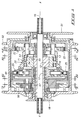
- the general nature of the continuously variable transmission can best be understood with respect to the presently preferred embodiment, which is detailed in Figs. 1-7.
- This form of the transmission has been developed specifically for use in a rear bicycle wheel hub.
- the transmission components can be modified to adapt them to applications other than bicycles.
- the basics of the invention include a variable eccentric assembly 11, a plurality of input and output vanes 22, 25, and rotatable input and output ratchets 35, 40.
- the input vanes each have an inner end, an outer end and an intermediate section.
- the input vanes are rotatably supported about a central axis X-X at their respective inner ends for variable rotation about the central axis in relation to one another.
- the input vanes 22 are pivotally and slidably coupled to the variable eccentric assembly 11 at their respective intermediate sections.
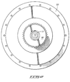
- a rotatable input ratchet 35 is concentric with the central axis X-X. It includes a directionally toothed driving ring 36 circumferentially surrounding the input vanes 22. The outer ends of the respective input vanes 22 each have a yieldable tooth selectively engaging the driving ring 36 of input ratchet 35 (see Fig. 4).
- An input drive element shown as a chain-driven sprocket 51, is operably coupled to input ratchet 35 to impart sequential driving engagement between the drive ring 36 of the input ratchet and the outer ends of the sequentially operating input vanes 22.
- the transmission further comprises an axially spaced set of output vanes 25.
- the respective output vanes 25 each also have an inner end, an outer end, and an intermediate section. They are rotatably supported about the central axis X-X at their respective inner ends for variable rotation about the central axis in relation to one another.
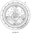
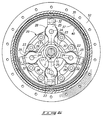
- the output vanes 25 are pivotally and slidably coupled to the variable eccentric assembly 11 at their respective intermediate sections (See Fig. 6).
- a rotatable output ratchet 40 is concentric with the central axis X-X. It includes a directionally toothed driven ring 37 circumferentially surrounding the output vanes 25.
- the toothed rings 36 and 37 of the respective input and output ratchets 35 and 40 have oppositely facing circular patterns of internal teeth formed thereon.
- the outer ends of the respective output vanes 25 each have a yieldable tooth selectively engaging the teeth about the driven ring 37.
- the teeth on the respective output vanes 25 face oppositely to the teeth on the input vanes 22.
- An output or driven member is illustrated as a bicycle wheel hub 52. It is operably coupled to output ratchet 40 for rotation about the central axis X-X in response to sequential driving engagement between the outer ends of the output vanes 25 and the driven ring 37 of the output ratchet 40.
- the bicycle transmission shown in the drawings includes coaxial first and second rotatable members in the form of a drive sprocket 51 and a driven wheel hub 52. They are arranged on the transmission for independent rotation about the central axis X-X of the transmission.
- the eccentric assembly 11 includes a cylindrical outer surface 16 formed about an eccentric axis (indicated by the letter "E” in Figs. 4 and 6) that is parallel and radially adjustable relative to the central axis X-X.
- Orbiter 20 is rotatably mounted by the cylindrical surface 16 for rotational movement about the variable eccentric axis.
- the axially spaced input and output ratchets 35, 40 are coaxially positioned about the central axis X-X at opposite axial ends of the orbiter 20. They include oppositely facing circular patterns of internal teeth formed thereon. Input and output ratchets 35, 40 are each coaxially centered about the central axis X-X.
- a plurality of input vanes 22 are located within the toothed ring 36 of input ratchets 35.
- Each input vane 22 has a first or inner end including a hub 26 coaxially pivoted about the central axis X-X.
- the four input vanes 22 are identical to one another, but their respective inner hub sections are axially offset from one another and overlap each other to properly arrange the input vanes 22 in a common transverse plane.
- each input vane 22 includes at least one yieldable tooth. It is complementary to and selectively engage the internal teeth about tooth ring 36 of input ratchet 35 during a portion of each complete revolution of the eccentric assembly 11.
- Each input vane 22 is operably interconnected to orbiter 20 at a location intermediate its first and second ends.
- a plurality of similar output vanes are provided at the opposite axial end of orbiter 20.
- Each output vane 25 has a first or inner end coaxially pivoted about the central axis X-X.
- the hubs 30 of the output vanes 25 are also offset so as to arrange the output vanes 25 across a common plane in the transmission.
- each output vane 25 includes at least one yieldable tooth. It is complementary to and selectively engage the internal teeth about the toothed ring 37 of output ratchet 40 during a portion of each complete revolution of eccentric assembly 11.
- Each output vane 25 is operably interconnected to the orbiter 20 at a location intermediate its first and second ends.
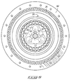
- the illustrated eccentric assembly 11 is a double eccentric including an inner eccentric 12 and an outer eccentric 13 (See Fig. 5). Inner and outer eccentric elements 12, 13 are independently rotatable relative to one another.
- the inner eccentric element 12 has an inner cylindrical surface rotatably mounted about the central axis X-X by central shaft 10. It includes an integral tubular extension shaft 17 leading outward at one axial end of the transmission. The outer end of extension shaft 17 mounts a small sprocket 18 or an equivalent gear or other device capable of imparting rotational movement to shaft 17 and inner eccentric 12.
- the inner eccentric 12 has an outer eccentric cylindrical surface centered about an axis radially offset from central axis X-X.
- the outer eccentric element 13 has an inner cylindrical surface rotatably mounted about the eccentric outer cylindrical surface of the inner eccentric member 12. As previously described, it includes an eccentric outer cylindrical surface 16 about which the orbiter 20 is supported.
- the outer eccentric element 13 within eccentric assembly 11 is prevented from rotating relative to central shaft 10 with respect to the central axis X-X.
- the outer eccentric 13 is free to be shifted radially with respect to axis X-X as the degree of eccentricity is varied during operation of the transmission.
- the transmission is illustrated in Figs. 1 and 5 with the eccentric outer surface 16 concentric with the central axis X-X. In this position, the transmission is locked-up and has a 1 to 1 gear ratio.
- the inner eccentric 12 has been turned 180° relative to the stationary outer eccentric 13 for illustration of the alternative extreme operational positions of the transmission components. In the specific form of the unit as shown, the gear ratio is then 1 to 2.6.
- the eccentric assembly 11 is operably connected to the fixed central support shaft 10 which in turn is centered about the central axis X-X. Interconnection is accomplished through a transverse shift triangle 53 located adjacent to one axial end of the eccentric assembly 11 (see Fig. 5). Triangle 53 is fixed to shaft 10. Shaft 10 is normally locked to the supporting wheel frame of a bicycle on which the surrounding wheel hub 52 is mounted. Since shaft 10 is stationary in this form of the invention, the outer eccentric 13 is held stationary in unison with it.
- the eccentric movement imparted to the outer eccentric 13 is accommodated by interconnecting bushings 54 that are rotatably carried on shift triangle 53 for motion about axes parallel to central axis X-X.
- Each bushing 54 includes an integral projecting pin 55 rotatably received within complementary apertures at the adjacent axial end of outer eccentric 13 (see Fig. 1).
- the outer eccentric 13 remains adjustable in a radial direction relative to axis X-X, but is locked rotationally to the central shaft 10.
- the illustrated sprocket 18 serves as an adjusting mechanism operably connected to the inner eccentric element 12.
- the sprocket 18 might have a short length of chain (not shown) partially wrapped about it and connected to a controlling shift cable (not shown) at one or both ends of the chain. By pulling on one or both ends of the chain, the sprocket 18 can be pivoted about the axis X-X to angularly shift the position of inner eccentric element 12 relative to central shaft 10 and outer eccentric element 13.
- the simplified adjusting mechanism described in the previous paragraph requires the application of substantial force if adjustment is attempted while the transmission is operating under load. However, this can be achieved by use of a worm and worm gear adjusting mechanism, which would provide greater torque to the extension shaft 17 and the benefits of an irreversible turning gear system.
- the planetary transmission is interposed between the hub 52 and output ratchet 40. It includes a ring gear 56 fixed to input ratchet 35 and a sun gear 57 fixed to the hub 52 (see Fig. 1).
- the ring gear 56 and sun gear 57 are drivingly interconnected by a series of planet gears 58 rotatably supported on a planetary carrier 60.
- Planet carrier 60 is rotatable about the central axis X-X and is integrally connected to output ratchet 40. It rotatably supports the planetary gears 58 in meshing engagement with both the ring and sun gears to provide the desired multiplier at the output of the operational transmission.
- orbiter 20 is freely rotatable about the outer circular surface of the eccentric assembly 11.
- the orbiter 20 includes four projecting axial pins 21 (see Figs. 1 and 4) respectively engaged within slots 27 formed through the four input vanes 22.
- orbiter 20 includes a transverse face (see Fig. 6) including four radial slots 23 each formed by two parallel, inwardly facing axial walls on the orbiter 20. The parallel walls are engaged by individual rollers 28 rotatably carried on the four output vanes 25. The rollers 28 in turn are supported by shafts 24 fixed to and aligned axially on the output vanes 25 (see Figs. 1 and 6)
- Both the input and output vanes 22, 25 are mounted concentrically with the axis of shaft 10.
- Each vane includes a support hub 26, 30 at its inner end.
- the hubs 26 of the input vanes 22 are rotatably mounted about the shaft 10 (see Figs. 1 and 4).
- the respective hubs 26 include axial offsets to locate the four input vanes 22 in a common plane perpendicular to the axis of shaft 10.
- output vanes 25 include hubs 30 at one of their ends. They also are provided with axial offsets to locate the output vanes 24 in a common plane perpendicular to the axis of shaft 10.
- each input vane 22 pivotally supports a single tooth pawl 31.
- the outer end of each output vane 25 slidably supports a single tooth pawl 32.
- the two illustrated forms of pawls 31 and 32 are functionally identical. They are interchangeable in the design of a specific transmission according to this invention.
- Pawls 31 and 32 are operationally reversed in position on the input and output vanes 22, 25. They face in opposite directions in the two vane sets.
- Each pawl 31, 32 is yieldably biased by a spring which urges the transverse tooth across the pawl to a radially extended position.
- the vanes 22, 25 are thus pivotally mounted at their inner ends about the axis of shaft 10. Their instantaneous angular positions relative to that axis are controlled by their interconnections to the ends of orbiter 20. These instantaneous angular positions in turn are a function of the eccentricity of the double eccentric 11 about which the orbiter 20 rotates.
- the pawls 31 on input vanes 22 are engaged by inwardly directed cylindrical ratchet teeth formed on the toothed ring 36 of input ratchet 35.
- Output ratchet 40 has oppositely directed ratchet teeth formed on the toothed ring 37 engaged by the pawls 32 on the output vanes 24.
- the continuously variable transmission illustrated within Figs. 1-7 receives input torque through drive sprocket 51 and input ratchet 35, which in turn rotates in unison with ring gear 56 of the multiplier planetary transmission.
- Input torque is directly transferred from input ratchet 35 to the angularly movable and rotatable input vanes 22.
- Each vane 22 will sequentially be drivingly engaged with the toothed ring 36 during 90° of the full rotational cycle of orbiter 20 about its eccentric axis of rotation.
- the resulting motion of the sequentially-operative vanes 22 is transferred to orbiter 20 through the interconnecting pins 21.
- vanes 22 will lightly drag over the toothed ring 36 and will become radially disengaged from the ratchet teeth as a result of the pivotal forces exerted upon them due to their respective interconnections to the orbiter 20.
- the vaned transmission achieves a gear ratio because of the differing radii of engagement between the orbiter 20, the input vanes 22 and the output vanes 25.
- the axial centers of pins 21 which engage elongated slots 27 within input vanes 22 are closer to axis X-X than are the corresponding centers of shafts 24 which support rollers 28 located within the output vanes 25.
- the size relationships between these radii should be selected to provide a maximum radius of engagement to the output vanes 25 within the limiting size parameters of the transmission. It is also important to provide the maximum available difference in the effective radii at which the orbiter 20 is interconnected to the two sets of vanes 22 and 25. These relationships have been found to minimize the usual "stutter" or velocity deviations encountered during operation of this type of transmission.
- the input vanes 22 are interconnected to orbiter 20 by pins on the orbiter, while the output vanes 25 are interconnected to orbiter 20 by radial slots bearing against vane rollers 28.
- These interconnections can be reversed in the design of the respective input and output vanes.
- both sets of vanes might be connected to the orbiter by pins, or both might include rollers that are engaged along radial slot walls on the orbiter. The choices of orbiter interconnections will depend upon the encountered loads, spatial limitations, and end use applications for the transmission.
- the four input vanes 22 be offset by an angle of 45° with respect to the corresponding four output vanes 25.
- an odd number of vanes is used in the sets of input and output vanes, they should be in alignment with one another at the respective ends of orbiter 20.
- the powered input would then be a concentric central shaft serving as the bicycle crankshaft. It could be surrounded by a tubular shaft locked to the bicycle frame and fixed to the shift triangle holding the outer eccentric in a stationary angular position.
- the input ratchet would then be operatively fixed to the crankshaft and rotate in unison with it.
- the rotating output member of this alternative form of the invention could be a conventional driving chain sprocket, but might alternatively be in the form of a pulley, crank or any desired rotating output element. It can be fixed to rotate in unison with the sun gear in the planetary cluster previously described.
- the transmission components could be separately located on rotationally interconnected shafts, such as the driven wheel hub and crank shaft of a bicycle.
- the vaned transmission might be incorporated within the bottom bracket shell of a bicycle and the associated transmission multiplier might be incorporated within the associated driven wheel hub.
- a second stage planetary transmission while desirable, is not a necessary feature of the basic transmission. It does provide an extended gear ratio range, particularly within the size limitations encountered in bicycle applications. It also lends itself to design of a compact two-speed output for the basic transmission structure. However, the basic vane transmission could be utilized in conjunction with a different type of single speed or multispeed transmission.
- the illustrated form of the planetary transmission can be modified to provide for a two-stage output transmission. This would require that the supporting casing 66 for ring gear 56 be axially movable along axis X-X.
- the ring gear might then be alternately coupled to the input ratchet 35 (as shown) or to a fixed frame member (not shown) to modify operation of the multiplying planetary transmission as desired during operation of the transmission.
- This two stage operation when synchronized with operation of the vaned transmission, can double its gear ratio and effectively extend it throughout the normal full range of ratios expected within a bicycle environment.
- casing 66 As an example, if casing 66 were to be shifted to the right in Fig. 1, it might lock up and rotate in unison with the input ratchet 35 in the manner generally described with respect to the illustrated embodiment. However, if casing 66 were to be shifted to the left to assume a disengaged position relative to the input ratchet 35, the ring gear 56 would then be held stationary by engagement of an adjacent frame member (not shown). Thus, slight axial movement of casing 66 might provide two different speed ratios in the second stage planetary transmission included within the one transmission housing. Various forms of couplings, clutches, brakes and other control mechanisms can be utilized to achieve this expanded range of operation.
Landscapes
- Engineering & Computer Science (AREA)
- Mechanical Engineering (AREA)
- General Engineering & Computer Science (AREA)
- Chemical & Material Sciences (AREA)
- Combustion & Propulsion (AREA)
- Transportation (AREA)
- Retarders (AREA)
- Transmission Devices (AREA)
- Control Of Transmission Device (AREA)
- Valve Device For Special Equipments (AREA)
- Valve-Gear Or Valve Arrangements (AREA)
Claims (12)
- Kontinuierlich verstellbares Getriebe, welches ein ringförmiges Klinkenrad (35), das konzentrisch zu einer Achse (X-X) ist und auf dieser drehbar ist, und einen Orbiter (20) aufweist, welcher relativ zu der Achse (X-X) drehbar ist und einen selektiv veränderlichen Exzentrizitätsgrad aufweist, wobei das Getriebe des weiteren eine Vielzahl von Rippen (22) aufweist, welche jeweils einen inneren drehbar an der Achse (X-X) gelagerten Endbereich, einen äußeren Endbereich und einen mittleren Bereich aufweisen, und wobei jede der Rippen (22) an ihrem äußeren Endbereich einen biegsamen bzw. nachgiebigen Zahn (31), welcher mit einem richtungsverzahnten Antriebsring (36) des Klinkenrades (35) in Eingriff bringbar ist, sowie ein Antriebselement (51) aufweist, welches antriebsmäßig mit dem Klinkenrad (35) verbunden ist, um einen sequentiellen Antriebseingriff zwischen dem Antriebsring (36) des Klinkenrades (35) und den äußeren Endbereichen der Rippen (22) zu übertragen,
dadurch gekennzeichnet, daß
die Rippen (22) verschieblich und schwenkbar mit dem Orbiter (20) an ihren jeweiligen mittleren Bereichen verbunden sind. - Getriebe nach Anspruch 1,
dadurch gekennzeichnet, daß
ein zweites ringförmiges Klinkenrad (40) vorgesehen ist, welches auf der Achse (X-X) drehbar ist, eine Vielzahl von zweiten Rippen (25), welche jeweils einen inneren Endbereich, einen äußeren Endbereich und einen mittleren Bereich aufweisen, wobei die zweiten Rippen an ihren jeweiligen inneren Endbereichen der zweiten Rippen (25), und zwar zur variablen Rotation der zweiten Rippen (25) relativ zueinander um die Achse (X-X), wobei die zweiten Rippen (25) des weiteren gelenkig und verschieblich mit dem Orbiter (20) an ihren jeweiligen mittleren Bereichen verbunden sind, und wobei jede der zweiten Rippen (25) an ihrem äußeren Endbereich einen nachgiebigen Zahn (32) aufweist, welcher mit einem verzahnten angetriebenen Ring (37) des zweiten Klinkenrads (40) in Eingriff bringbar ist, wobei das zweite Klinkenrad (40) antriebsfähig mit einem auf der Achse (X-X) drehbaren Antriebselement (57) verbunden ist, und zwar als Reaktion auf den sequentiellen Antriebseingriff zwischen den äußeren Endbereichen der zweiten Rippen (25) und dem angetriebenen Ring (37) des zweiten Klinkenrades (40). - Getriebe nach Anspruch 2,
dadurch gekennzeichnet, daß
das Getriebe darüber hinaus eine exzentrische Baugruppe (11) aufweist, welche ein äußeres Bauteil (13) aufweist, welches relativ zu der Achse (X-X) radial einstellbar ist, und der Orbiter (20) drehbar auf dem Bauteil (13) angebracht ist, wobei jeder der ersten und zweiten Rippen (22,25) betriebsfähig, radial und einstellbar an den mittleren Bereichen der Flügel (22,25) mit dem Orbiter (20) verbunden ist. - Getriebe nach Anspruch 3,
dadurch gekennzeichnet, daß
die exzentrische Baugruppe (11) einen inneren Bereich (12) aufweist, welcher drehbar auf einer festen Welle (10) angebracht ist, deren zentrale Längsachse koaxial mit der Achse (X-X) ist. - Getriebe nach Anspruch 4,
dadurch gekennzeichnet, daß
die Achsen der Bauteile (12,13) zueinander und zu der Achse (X-X) exzentrisch sind. - Getriebe nach Anspruch 5,
dadurch gekennzeichnet, daß
das äußere Bauteil (13) betriebsfähig mit der Welle (10) verbunden ist, und zwar derart, daß sie relativ zu der Welle (10) nicht drehbar ist. - Getriebe nach Anspruch 6,
dadurch gekennzeichnet, daß
ein Einstellmechanismus (18) vorgesehen ist, welcher mit der Welle (10) betriebsfähig verbunden ist. - Getriebe nach einem der Ansprüche 3 bis 7,
dadurch gekennzeichnet, daß
zwischen dem verbleibenden, drehbaren Element und dem Abtriebsklinkenrad (40) ein Planetengetriebe vorgesehen ist, wobei das Planetengetriebe ein Hohlrad (56), welches zur Rotation in Übereinstimmung mit dem ersten drehbaren Element angeordnet und um die zentrale Achse zentriert ist, ein Sonnenrad (57), welches auf dem zweiten drehbaren Element gebildet und um die zentrale Achse zentriert ist, und einen Planetenradträger (60) aufweist, welcher um die zentrale Achse drehbar und betriebsfähig mit dem Abtriebsklinkenrad (40) verbunden ist, wobei der Planetenradträger (60) eine Vielzahl von sowohl mit dem Ring- als auch mit dem Sonnenrad (56,57) in verzahntem Eingriff stehende Planetenräder (58) in drehbarer Art und Weise trägt. - Getriebe nach einem der Ansprüche 2 bis 8,
dadurch gekennzeichnet, daß
das erste Klinkenrad (35) betriebsfähig mit einem Kettenrad (51) verbunden ist, und daß das zweite Klinkenrad (40) betriebsfähig mit einer Fahrradnabe (52) verbunden ist. - Getriebe nach Anspruch 3,
dadurch gekennzeichnet, daß
der Radius, an welchem der Orbiter (20) mit den zweiten Rippen (25) verbunden ist, so ausgewählt ist, daß er einen maximalen Radius des Eingriffs mit den zweiten Rippen (25) innerhalb der begrenzenden Größenparameter des Getriebes ermöglicht. - Getriebe nach Anspruch 3,
dadurch gekennzeichnet, daß
die Größe des Orbiters (20) und der Rippen (22,25) so ausgewählt ist, daß sie den maximal möglichen Unterschied bezüglich des effektiven Radiuses bieten, an welchem der Orbiter (20) mit den ersten und zweiten Rippen (22,25) verbunden ist. - Getriebe nach Anspruch 1,
dadurch gekennzeichnet, daß
die Rippen (22) mit dem Orbiter (20) an ihren jeweiligen mittleren Bereichen an einem nicht festgelegten Drehpunkt verbunden sind, dessen Position auf jeder Rippe sich verändert, wenn das Getriebe angetrieben wird, und zwar in einem Ausmaß, welches von dem Exzentrizitätsgrad abhängt, welcher von dem Orbiter (20) festgelegt ist.
Applications Claiming Priority (3)
| Application Number | Priority Date | Filing Date | Title |
|---|---|---|---|
| US498189 | 1995-07-05 | ||
| US08/498,189 US5632702A (en) | 1995-07-05 | 1995-07-05 | Continuously variable transmission |
| PCT/US1996/011266 WO1997002175A1 (en) | 1995-07-05 | 1996-07-02 | Continuously variable transmission |
Publications (2)
| Publication Number | Publication Date |
|---|---|
| EP0833768A1 EP0833768A1 (de) | 1998-04-08 |
| EP0833768B1 true EP0833768B1 (de) | 1999-06-09 |
Family
ID=23979953
Family Applications (1)
| Application Number | Title | Priority Date | Filing Date |
|---|---|---|---|
| EP96923636A Expired - Lifetime EP0833768B1 (de) | 1995-07-05 | 1996-07-02 | Stufenlos verstellbares getriebe |
Country Status (9)
| Country | Link |
|---|---|
| US (1) | US5632702A (de) |
| EP (1) | EP0833768B1 (de) |
| AT (1) | ATE181026T1 (de) |
| AU (1) | AU6451396A (de) |
| DE (1) | DE69602840T2 (de) |
| DK (1) | DK0833768T3 (de) |
| ES (1) | ES2136425T3 (de) |
| GR (1) | GR3031194T3 (de) |
| WO (1) | WO1997002175A1 (de) |
Families Citing this family (15)
| Publication number | Priority date | Publication date | Assignee | Title |
|---|---|---|---|---|
| US6055878A (en) * | 1997-12-16 | 2000-05-02 | Speed Control, Inc. | Adjustable eccentric shift mechanisms |
| US6050584A (en) * | 1998-04-07 | 2000-04-18 | Sibson; Brian | Bicycle placing rider in substantially semi-prone riding position |
| US6354976B1 (en) | 1998-07-02 | 2002-03-12 | Speed Control, Inc. | Transmissions, transmission lock assemblies, methods of adjusting a gear ratio of a transmission, and methods of forming a transmission shift mechanism |
| US5964677A (en) * | 1998-07-02 | 1999-10-12 | Speed Control, Inc. | Shift mechanisms, lock assemblies and methods of adjusting a gear ratio of a transmission |
| DE19953643B4 (de) * | 1999-11-09 | 2005-02-03 | Innowacja Consulting | Stufenloses Getriebe |
| DE10301348A1 (de) * | 2003-01-16 | 2004-07-29 | Satellite Gear Systems Ltd. | Stufenlos regelbares Getriebe |
| WO2007019313A2 (en) * | 2005-08-05 | 2007-02-15 | Differential Dynamics Corporation | Variable motion control devices for transmission and other implementations and methods of use thereof |
| US20070155567A1 (en) * | 2005-11-22 | 2007-07-05 | Fallbrook Technologies Inc. | Continuously variable transmission |
| AT507482B1 (de) | 2008-03-21 | 2010-08-15 | Nagel Edmund | Getriebe mit stufenlos veränderbarer übersetzung zwischen einer eingangswelle und einer ausgangswelle |
| AT509479B1 (de) | 2010-05-03 | 2011-09-15 | Nagel Edmund F | Gekapseltes fahrrad-stufenlosgetriebe |
| JP5543529B2 (ja) * | 2012-06-03 | 2014-07-09 | 稔 中川 | 遊星ギヤ無段変速機構 |
| DE102012020905B3 (de) * | 2012-10-24 | 2014-02-06 | Audi Ag | Stufenlosgetriebe für ein Kraftfahrzeug |
| US10094452B1 (en) | 2013-03-05 | 2018-10-09 | Mark B. Sullivan | Continuously variable transmission for a bicycle |
| JPWO2015079837A1 (ja) * | 2013-11-29 | 2017-03-16 | 稔 中川 | 無段変速機 |
| ITUB20156266A1 (it) * | 2015-12-03 | 2017-06-03 | Constantin Edyson Pavilcu | Trasmissione a rapporto di velocita variabile |
Family Cites Families (12)
| Publication number | Priority date | Publication date | Assignee | Title |
|---|---|---|---|---|
| DE393180C (de) * | 1923-03-30 | 1924-04-04 | Bruno Schroeder | Kurbelgetriebe |
| US1872636A (en) * | 1931-01-17 | 1932-08-16 | Galloway Engineering Company L | Variable speed transmission |
| US4164153A (en) * | 1977-12-09 | 1979-08-14 | Moritsch Denis J | Device for use in mechanical power transmission system |
| IT1159880B (it) * | 1978-07-05 | 1987-03-04 | Whitehead Moto Fides Spa | Meccanismo per variare in modo proporzionalmente continuo la velocita' angolare tra due alberi |
| JPS55132372A (en) * | 1978-09-23 | 1980-10-15 | Akira Korosue | Nonnstage transmission for bicycle |
| US4660427A (en) * | 1984-10-15 | 1987-04-28 | Fenton John W | Continuously variable transmission |
| JPS61226388A (ja) * | 1985-04-01 | 1986-10-08 | ブリヂストンサイクル株式会社 | 無段変速装置 |
| US4732054A (en) * | 1985-06-27 | 1988-03-22 | Bridgestone Cycle Co., Ltd. | Stepless speed change device |
| EP0411190A1 (de) * | 1989-08-03 | 1991-02-06 | Look S.A. | Stufenloses Getriebe |
| KR100326589B1 (ko) * | 1993-08-30 | 2002-06-28 | 모리스 조페 | 전동 메카니즘 |
| US5454766A (en) * | 1994-06-24 | 1995-10-03 | Speed Control, Inc. | Continuously variable transmission having a double eccentric shaft and a worm gear adjusting mechanism |
| US5516132A (en) * | 1994-07-22 | 1996-05-14 | Simkins; Barry A. | Variable-speed transmission |
-
1995
- 1995-07-05 US US08/498,189 patent/US5632702A/en not_active Expired - Fee Related
-
1996
- 1996-07-02 AU AU64513/96A patent/AU6451396A/en not_active Abandoned
- 1996-07-02 AT AT96923636T patent/ATE181026T1/de not_active IP Right Cessation
- 1996-07-02 EP EP96923636A patent/EP0833768B1/de not_active Expired - Lifetime
- 1996-07-02 DE DE69602840T patent/DE69602840T2/de not_active Expired - Fee Related
- 1996-07-02 DK DK96923636T patent/DK0833768T3/da active
- 1996-07-02 ES ES96923636T patent/ES2136425T3/es not_active Expired - Lifetime
- 1996-07-02 WO PCT/US1996/011266 patent/WO1997002175A1/en not_active Ceased
-
1999
- 1999-09-09 GR GR990402288T patent/GR3031194T3/el unknown
Also Published As
| Publication number | Publication date |
|---|---|
| DK0833768T3 (da) | 1999-12-27 |
| AU6451396A (en) | 1997-02-05 |
| ATE181026T1 (de) | 1999-06-15 |
| WO1997002175A1 (en) | 1997-01-23 |
| ES2136425T3 (es) | 1999-11-16 |
| DE69602840T2 (de) | 2000-01-27 |
| GR3031194T3 (en) | 1999-12-31 |
| EP0833768A1 (de) | 1998-04-08 |
| US5632702A (en) | 1997-05-27 |
| DE69602840D1 (de) | 1999-07-15 |
Similar Documents
| Publication | Publication Date | Title |
|---|---|---|
| EP0833768B1 (de) | Stufenlos verstellbares getriebe | |
| US5454766A (en) | Continuously variable transmission having a double eccentric shaft and a worm gear adjusting mechanism | |
| WO2001073319A1 (en) | Continuous variable transmission | |
| EP0159855B1 (de) | Stufenlose Fahrradgangschaltung | |
| US4807494A (en) | Stepwise variable speed planetary drive | |
| CA1077743A (en) | Stepless, variable stroke drive having a non-rotating cam | |
| JPH09502785A (ja) | トランスミッション機構 | |
| EP0502061B1 (de) | Reibscheibentoroidgetriebe | |
| MXPA02006035A (es) | Aparato para el cambio de velocidad de bicicletas. | |
| US5048358A (en) | Rotary phased radial thrust variable drive transmission | |
| RU97115942A (ru) | Устройство преобразования мощности для велосипедной втулки | |
| EP0208473B1 (de) | Stufenloses Getriebe | |
| US6068570A (en) | Variable speed transmission system and differential | |
| CN102265064B (zh) | 无级变速装置 | |
| US4321842A (en) | Compound epicyclic cog belt speed reducer | |
| US5116292A (en) | Variable drive transmission | |
| GB1597588A (en) | Variable throw crank assemblies and variable speed transmissions incorporating the same | |
| WO1995000775A1 (en) | Variable ratio power transmission | |
| WO2004040168A1 (ja) | 無段変速装置 | |
| EP0258369A1 (de) | Selbsteinstellendes getriebe | |
| CA1154982A (en) | Compound epicyclic cog belt speed reducer | |
| JPH06235444A (ja) | チエン式遊星差動減速機 | |
| EP0547802A2 (de) | Wechselgetriebe | |
| US4186624A (en) | Sequential drive mechanism | |
| KR101213547B1 (ko) | 무단변속장치 |
Legal Events
| Date | Code | Title | Description |
|---|---|---|---|
| PUAI | Public reference made under article 153(3) epc to a published international application that has entered the european phase |
Free format text: ORIGINAL CODE: 0009012 |
|
| 17P | Request for examination filed |
Effective date: 19980128 |
|
| AK | Designated contracting states |
Kind code of ref document: A1 Designated state(s): AT BE CH DE DK ES FI FR GB GR IE IT LI LU MC NL PT SE |
|
| GRAG | Despatch of communication of intention to grant |
Free format text: ORIGINAL CODE: EPIDOS AGRA |
|
| GRAG | Despatch of communication of intention to grant |
Free format text: ORIGINAL CODE: EPIDOS AGRA |
|
| GRAH | Despatch of communication of intention to grant a patent |
Free format text: ORIGINAL CODE: EPIDOS IGRA |
|
| 17Q | First examination report despatched |
Effective date: 19981113 |
|
| GRAH | Despatch of communication of intention to grant a patent |
Free format text: ORIGINAL CODE: EPIDOS IGRA |
|
| GRAA | (expected) grant |
Free format text: ORIGINAL CODE: 0009210 |
|
| AK | Designated contracting states |
Kind code of ref document: B1 Designated state(s): AT BE CH DE DK ES FI FR GB GR IE IT LI LU MC NL PT SE |
|
| REF | Corresponds to: |
Ref document number: 181026 Country of ref document: AT Date of ref document: 19990615 Kind code of ref document: T |
|
| REG | Reference to a national code |
Ref country code: CH Ref legal event code: EP |
|
| REF | Corresponds to: |
Ref document number: 69602840 Country of ref document: DE Date of ref document: 19990715 |
|
| REG | Reference to a national code |
Ref country code: IE Ref legal event code: FG4D |
|
| ITF | It: translation for a ep patent filed | ||
| ET | Fr: translation filed | ||
| REG | Reference to a national code |
Ref country code: ES Ref legal event code: FG2A Ref document number: 2136425 Country of ref document: ES Kind code of ref document: T3 |
|
| REG | Reference to a national code |
Ref country code: PT Ref legal event code: SC4A Free format text: AVAILABILITY OF NATIONAL TRANSLATION Effective date: 19990906 |
|
| REG | Reference to a national code |
Ref country code: CH Ref legal event code: NV Representative=s name: CABINET ROLAND NITHARDT CONSEILS EN PROPRIETE INDU |
|
| REG | Reference to a national code |
Ref country code: DK Ref legal event code: T3 |
|
| PLBE | No opposition filed within time limit |
Free format text: ORIGINAL CODE: 0009261 |
|
| STAA | Information on the status of an ep patent application or granted ep patent |
Free format text: STATUS: NO OPPOSITION FILED WITHIN TIME LIMIT |
|
| 26N | No opposition filed | ||
| PGFP | Annual fee paid to national office [announced via postgrant information from national office to epo] |
Ref country code: MC Payment date: 20000712 Year of fee payment: 5 |
|
| PGFP | Annual fee paid to national office [announced via postgrant information from national office to epo] |
Ref country code: LU Payment date: 20000724 Year of fee payment: 5 |
|
| PGFP | Annual fee paid to national office [announced via postgrant information from national office to epo] |
Ref country code: SE Payment date: 20010620 Year of fee payment: 6 Ref country code: FI Payment date: 20010620 Year of fee payment: 6 |
|
| PGFP | Annual fee paid to national office [announced via postgrant information from national office to epo] |
Ref country code: NL Payment date: 20010621 Year of fee payment: 6 Ref country code: GB Payment date: 20010621 Year of fee payment: 6 Ref country code: CH Payment date: 20010621 Year of fee payment: 6 Ref country code: AT Payment date: 20010621 Year of fee payment: 6 |
|
| PGFP | Annual fee paid to national office [announced via postgrant information from national office to epo] |
Ref country code: DK Payment date: 20010622 Year of fee payment: 6 |
|
| PGFP | Annual fee paid to national office [announced via postgrant information from national office to epo] |
Ref country code: PT Payment date: 20010627 Year of fee payment: 6 |
|
| PG25 | Lapsed in a contracting state [announced via postgrant information from national office to epo] |
Ref country code: LU Free format text: LAPSE BECAUSE OF NON-PAYMENT OF DUE FEES Effective date: 20010702 |
|
| PGFP | Annual fee paid to national office [announced via postgrant information from national office to epo] |
Ref country code: BE Payment date: 20010713 Year of fee payment: 6 |
|
| PGFP | Annual fee paid to national office [announced via postgrant information from national office to epo] |
Ref country code: IE Payment date: 20010720 Year of fee payment: 6 |
|
| PGFP | Annual fee paid to national office [announced via postgrant information from national office to epo] |
Ref country code: GR Payment date: 20010731 Year of fee payment: 6 |
|
| PGFP | Annual fee paid to national office [announced via postgrant information from national office to epo] |
Ref country code: ES Payment date: 20010808 Year of fee payment: 6 |
|
| REG | Reference to a national code |
Ref country code: GB Ref legal event code: IF02 |
|
| PG25 | Lapsed in a contracting state [announced via postgrant information from national office to epo] |
Ref country code: MC Free format text: LAPSE BECAUSE OF NON-PAYMENT OF DUE FEES Effective date: 20020201 |
|
| PG25 | Lapsed in a contracting state [announced via postgrant information from national office to epo] |
Ref country code: IE Free format text: LAPSE BECAUSE OF NON-PAYMENT OF DUE FEES Effective date: 20020702 Ref country code: GB Free format text: LAPSE BECAUSE OF NON-PAYMENT OF DUE FEES Effective date: 20020702 Ref country code: FI Free format text: LAPSE BECAUSE OF NON-PAYMENT OF DUE FEES Effective date: 20020702 Ref country code: AT Free format text: LAPSE BECAUSE OF NON-PAYMENT OF DUE FEES Effective date: 20020702 |
|
| PG25 | Lapsed in a contracting state [announced via postgrant information from national office to epo] |
Ref country code: SE Free format text: LAPSE BECAUSE OF NON-PAYMENT OF DUE FEES Effective date: 20020703 Ref country code: ES Free format text: LAPSE BECAUSE OF NON-PAYMENT OF DUE FEES Effective date: 20020703 |
|
| PG25 | Lapsed in a contracting state [announced via postgrant information from national office to epo] |
Ref country code: LI Free format text: LAPSE BECAUSE OF NON-PAYMENT OF DUE FEES Effective date: 20020731 Ref country code: DK Free format text: LAPSE BECAUSE OF NON-PAYMENT OF DUE FEES Effective date: 20020731 Ref country code: CH Free format text: LAPSE BECAUSE OF NON-PAYMENT OF DUE FEES Effective date: 20020731 Ref country code: BE Free format text: LAPSE BECAUSE OF NON-PAYMENT OF DUE FEES Effective date: 20020731 |
|
| PGFP | Annual fee paid to national office [announced via postgrant information from national office to epo] |
Ref country code: DE Payment date: 20021230 Year of fee payment: 7 |
|
| PGFP | Annual fee paid to national office [announced via postgrant information from national office to epo] |
Ref country code: FR Payment date: 20021231 Year of fee payment: 7 |
|
| BERE | Be: lapsed |
Owner name: *SPEED CONTROL INC. Effective date: 20020731 |
|
| PG25 | Lapsed in a contracting state [announced via postgrant information from national office to epo] |
Ref country code: PT Free format text: LAPSE BECAUSE OF NON-PAYMENT OF DUE FEES Effective date: 20030131 |
|
| PG25 | Lapsed in a contracting state [announced via postgrant information from national office to epo] |
Ref country code: NL Free format text: LAPSE BECAUSE OF NON-PAYMENT OF DUE FEES Effective date: 20030201 |
|
| PG25 | Lapsed in a contracting state [announced via postgrant information from national office to epo] |
Ref country code: GR Free format text: LAPSE BECAUSE OF NON-PAYMENT OF DUE FEES Effective date: 20030206 |
|
| GBPC | Gb: european patent ceased through non-payment of renewal fee |
Effective date: 20020702 |
|
| REG | Reference to a national code |
Ref country code: DK Ref legal event code: EBP |
|
| EUG | Se: european patent has lapsed | ||
| REG | Reference to a national code |
Ref country code: CH Ref legal event code: PL |
|
| NLV4 | Nl: lapsed or anulled due to non-payment of the annual fee |
Effective date: 20030201 |
|
| REG | Reference to a national code |
Ref country code: PT Ref legal event code: MM4A Free format text: LAPSE DUE TO NON-PAYMENT OF FEES Effective date: 20030131 |
|
| REG | Reference to a national code |
Ref country code: IE Ref legal event code: MM4A |
|
| PG25 | Lapsed in a contracting state [announced via postgrant information from national office to epo] |
Ref country code: DE Free format text: LAPSE BECAUSE OF NON-PAYMENT OF DUE FEES Effective date: 20040203 |
|
| PG25 | Lapsed in a contracting state [announced via postgrant information from national office to epo] |
Ref country code: FR Free format text: LAPSE BECAUSE OF NON-PAYMENT OF DUE FEES Effective date: 20040331 |
|
| REG | Reference to a national code |
Ref country code: FR Ref legal event code: ST |
|
| REG | Reference to a national code |
Ref country code: ES Ref legal event code: FD2A Effective date: 20030811 |
|
| PG25 | Lapsed in a contracting state [announced via postgrant information from national office to epo] |
Ref country code: IT Free format text: LAPSE BECAUSE OF NON-PAYMENT OF DUE FEES;WARNING: LAPSES OF ITALIAN PATENTS WITH EFFECTIVE DATE BEFORE 2007 MAY HAVE OCCURRED AT ANY TIME BEFORE 2007. THE CORRECT EFFECTIVE DATE MAY BE DIFFERENT FROM THE ONE RECORDED. Effective date: 20050702 |