EP0834400A2 - Absangvorrichtung für einen Tintenstrahldrucker - Google Patents
Absangvorrichtung für einen Tintenstrahldrucker Download PDFInfo
- Publication number
- EP0834400A2 EP0834400A2 EP97307809A EP97307809A EP0834400A2 EP 0834400 A2 EP0834400 A2 EP 0834400A2 EP 97307809 A EP97307809 A EP 97307809A EP 97307809 A EP97307809 A EP 97307809A EP 0834400 A2 EP0834400 A2 EP 0834400A2
- Authority
- EP
- European Patent Office
- Prior art keywords
- volume
- variable chamber
- slider
- valve
- suction apparatus
- Prior art date
- Legal status (The legal status is an assumption and is not a legal conclusion. Google has not performed a legal analysis and makes no representation as to the accuracy of the status listed.)
- Granted
Links
Images


Classifications
-
- B—PERFORMING OPERATIONS; TRANSPORTING
- B41—PRINTING; LINING MACHINES; TYPEWRITERS; STAMPS
- B41J—TYPEWRITERS; SELECTIVE PRINTING MECHANISMS, i.e. MECHANISMS PRINTING OTHERWISE THAN FROM A FORME; CORRECTION OF TYPOGRAPHICAL ERRORS
- B41J2/00—Typewriters or selective printing mechanisms characterised by the printing or marking process for which they are designed
- B41J2/005—Typewriters or selective printing mechanisms characterised by the printing or marking process for which they are designed characterised by bringing liquid or particles selectively into contact with a printing material
- B41J2/01—Ink jet
- B41J2/135—Nozzles
- B41J2/165—Prevention or detection of nozzle clogging, e.g. cleaning, capping or moistening for nozzles
- B41J2/16505—Caps, spittoons or covers for cleaning or preventing drying out
- B41J2/16508—Caps, spittoons or covers for cleaning or preventing drying out connected with the printer frame
Definitions
- the present invention generally relates to an inkjet printing system, and in particular to a suction apparatus which is used to clean an inkjet head.
- an inkjet printing system is equipped with an ink suction apparatus which draws ink sludge within ink nozzles and bubbles trapped in an ink supply system by applying a suction force. Such a suction operation is periodically performed to avoid the deterioration of print quality.
- a conventional suction pump has been disclosed in Japanese Patent Unexamined Publication No. 4-37557.
- the suction pump is provided with a piston performing a reciprocating motion in an inner cylinder and a piston valve which performs a reciprocating motion depending on the piston in a cylindrical space between the inner cylinder and an outer cylinder.
- the suction pump is further provided with an open/close valve and a pressure reducing means which is a space formed by the piston, open/close valve, and the open/close valve, the space varying in volume depending on the reciprocating motion of the piston.
- the pressure reducing means is arranged between the piston valve and the open/close valve.
- the conventional suction pump needs the piston valve and the open/close valve in addition to the pressure reducing means, resulting in the increased number of parts and the complicated mechanism. This causes the increased weight and further the increased cost of the pump.
- An object of the present invention is to provide a suction apparatus which can achieve high print quality with relatively simple arrangement.
- Another object of the present invention is to provide a suction apparatus which can achieve weight reduction.
- a volume-variable chamber having an inlet and an outlet is formed by a plurality of enclosing parts including an elastic part.
- the suction apparatus is further provided with a member for applying a force to the volume-variable chamber to change a volume thereof, the member including a valve for opening the outlet when the member decreases the volume of the volume-variable chamber and closing the outlet when the member increases the volume of the volume-variable chamber.
- the suction force is produced by the member changing the volume with relatively simple arrangement and reduced weight. Further, since the member includes the valve, the suction mechanism is achieved with the reduced amount of hardware.
- the suction apparatus may includes a driver for driving the member to change a volume of the volume-variable chamber such that the member is driven at a normal speed when the inkjet head is located at a home position thereof and at a relatively low speed when the inkjet head is not located at the home position.
- FIG. 1 there is shown an inkjet printing system employing an ink suction device according to the present invention.
- a carriage 101 carrying an ink tank 102 and an inkjet head 103 is fixed to a driving belt 104 and performs a reciprocating motion in an X direction by a spacing motor 105.
- the inkjet head 103 having a plurality of ink nozzles therein ejects ink particles from selected ink nozzles according to print data.
- the inkjet head 103 may use piezoelectric devices or heaters.
- a line feed motor 105 drives a form feed roller 107 to move a recording paper 108 in a Y direction at right angles to the X direction.
- the inkjet printing system is further equipped with a cap 109 connected to an ink suction device 110 through a suction pipe 111.
- the cap 109 is placed at a home position of the inkjet head 103 and comes in contact with the nozzle surface of the inkjet head 103 to draw ink sludge and bubbles as will be described hereinafter.
- the suction pipe 111 is connected to the suction hole of a frame 201 which is shaped like a disc.
- the frame 201, an elastic wall 202 and a bottom plate 203 are combined to form an inverted truncated cone chamber which is variable in volume due to the elasticity of the elastic wall 202.
- the elastic wall 202 and the bottom plate 203 are made of elastic material such as rubber and are molded in one piece.
- the elastic wall 202 is relatively thin and the bottom plate 203 is thick, the elastic wall 202 is deformed when a force is applied to the bottom plate 203 upwardly.
- the bottom plate 203 has a hole 204 formed at the center thereof.
- the shaft of a valve 205 can slide through the hole 204 with creating clearance between them to allow air and ink to pass through.
- the valve 205 is provided with a top plate 206 which can open or close the hole 204.
- the shaft of the valve 205 can also slide through the hole of a hollow cylindrical slider 207 which is shorter than the shaft of the valve 205.
- the cylindrical slider 207 has at least one groove 208 formed on the top surface of a flange thereof.
- the groove 208 allows the air and ink to be drained from the variable-volume chamber through the clearance between the hole 204 and the shaft of the valve 205 when the bottom plate 203 comes in contact with the slider 207 and the top plate 206 of the valve 205 is open.
- the cylindrical slider 207 further has an O ring 209 fixed therein to slide in a hole of a holder 210 with frictional resistance. It is necessary to produce sliding frictional resistance which is sufficiently greater than the maximum recovery force of the elastic wall 202 when it is deformed. More specifically, in the case where the elastic wall 202 is made of silicone rubber, the elastic wall 202 produces a recovery force of about 50g when it is deformed. Therefore, in the case where the volume inside the elastic wall 202 is set to the order of 2000 mm 3 , the sliding frictional resistance produced by the O ring 209 is preferably set to lOOg to 200g. If a sufficient frictional resistance is produced, another friction producing material would be used instead of the O ring 209. For example, rubber or molded resin may be used.
- the cylindrical slider 207 is stopped sliding downward by the flange on which the groove 208 is formed.
- the valve 205 is stopped sliding downward by the bottom plate 203 which comes in contact with the cylindrical slider 207.
- an ink absorber 211 in the shape of a ring is provided on the holder 209 around the slider 207.
- the shaft of the valve 205 protrudes from the lower end of the slider 207 and has a pin 212 on the lower part thereof.
- the pin 212 is engaged in an oval hole 214 which is formed at an end of an arm 213.
- the arm 213 is rotatably supported by a supporting point 215.
- the arm 213 is further provided with another oval hole 216 in the center thereof in which a pin 217 of a cam 218 is engaged. Therefore, when the cam 218 rotates, the arm 213 performs a reciprocating motion in Z direction.
- the valve 205 when the arm 213 moves upwardly from a bottom dead point, the valve 205 also moves upwardly while sliding in the slider 207. Therefore, the top plate 206 rises from the opening of the hole 204 to provide a passage from the space inside the elastic wall 202 to outside through the groove 208.
- the slider 207 starts sliding upwardly in the holder 210, which causes the bottom plate 203 to be pushed upwardly, resulting in deformation of the elastic wall 202.
- the volume inside the elastic wall 202 is reduced as the slider 207 slides upwardly with keeping the passage from the space inside the elastic wall 202 to outside through the groove 208.
- the valve 205 when the arm 213 moves downwardly from a top dead point, the valve 205 first moves downwardly while sliding in the slider 207. Since the frictional resistance between the slider 207 and the holder 210 is greater than the recovery force of the deformed elastic wall 202, the slider 207 does not move until the top plate 206 of the valve 205 comes in contact with the bottom plate 203. When the top plate 206 of the valve 205 comes in contact with the bottom plate 203, the inside space of the elastic wall 202 is isolated from outside except for the cap 109. Thereafter, the valve 205 further moves downward to push both the bottom plate 203 and the slider 207 downward while the top plate 206 of the valve 205 blocks the opening of the hole 204.
- the suction force is generated to draw ink and bubbles from the ink nozzles and the supply system and bubbles through the suction pipe 111.
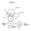
- a cycle of suction operation as shown in Figs. 3A-3C is repeated as the cam 218 rotates.
- the cam 218 is engaged with an idle gear 301 which is rotatably supported by a stud 302.
- the idle gear 301 is in turn engaged with a selected one of a normal gear 303 and a selected-tooth gear 304 by a slide gear mechanism 305.
- the normal gear 304 and the selected-tooth gear 305 can both slide along a shaft 306 and are rotated by the shaft 306 which is driven by the line feed motor 106. Therefore, the cam 217 is rotated by the line feed motor 106.
- the normal gear 304 and the selected-tooth gear 305 are both energized toward the carriage 101 by a spring 307 and are stopped sliding by a lever 308 which is rotatably supported by a stud 309.
- the lever 308 is pushed toward the spring 307 by the carriage 101 returning to its home position.
- the lever 308 shifts toward the carriage 101 due to the spring 307 so that the idle gear 301 is engaged with the selected-tooth gear 304. Contrarily, when the carriage 101 returns to the home position, the carriage 101 pushes the lever 308 toward the spring 307 to cause the normal gear 303 to be engaged with the idle gear 301. Therefore, the suction operation is performed at a normal speed when the carriage 101 comes in contact with the cap 109. On the other hand, while the carriage 101 traversing, the suction operation is performed at much lower speed.
- a turn of the shaft 306 causes the cam 218 to be rotated in steps when the selected-tooth gear 305 is selected. Therefore, the suction operation is performed very slowly while the carriage 101 is not located on the cap 109, preventing the ink from solidifying in the ink suction device 110 to ensure the normal operation and, at the same time, the long life time can be achieved.
Landscapes
- Ink Jet (AREA)
- Coating Apparatus (AREA)
Applications Claiming Priority (3)
| Application Number | Priority Date | Filing Date | Title |
|---|---|---|---|
| JP263234/96 | 1996-10-03 | ||
| JP8263234A JP2954038B2 (ja) | 1996-10-03 | 1996-10-03 | インク吸引手段 |
| JP26323496 | 1996-10-03 |
Publications (3)
| Publication Number | Publication Date |
|---|---|
| EP0834400A2 true EP0834400A2 (de) | 1998-04-08 |
| EP0834400A3 EP0834400A3 (de) | 1998-08-12 |
| EP0834400B1 EP0834400B1 (de) | 2002-02-06 |
Family
ID=17386649
Family Applications (1)
| Application Number | Title | Priority Date | Filing Date |
|---|---|---|---|
| EP97307809A Expired - Lifetime EP0834400B1 (de) | 1996-10-03 | 1997-10-02 | Absangvorrichtung für einen Tintenstrahldrucker |
Country Status (6)
| Country | Link |
|---|---|
| US (1) | US6145957A (de) |
| EP (1) | EP0834400B1 (de) |
| JP (1) | JP2954038B2 (de) |
| AU (1) | AU718689B2 (de) |
| CA (1) | CA2217306A1 (de) |
| DE (1) | DE69710282T2 (de) |
Families Citing this family (2)
| Publication number | Priority date | Publication date | Assignee | Title |
|---|---|---|---|---|
| JP4809178B2 (ja) * | 2006-09-29 | 2011-11-09 | 富士フイルム株式会社 | 液体吐出装置および液体供給方法 |
| JP4958533B2 (ja) * | 2006-12-19 | 2012-06-20 | キヤノン株式会社 | インクジェット記録装置 |
Family Cites Families (9)
| Publication number | Priority date | Publication date | Assignee | Title |
|---|---|---|---|---|
| JPS5784887A (en) * | 1980-11-17 | 1982-05-27 | Canon Inc | Suction pump for restoring ink-jetting ability of ink jet recorder |
| JPH02122940A (ja) * | 1988-11-02 | 1990-05-10 | Canon Inc | インクカートリッジ |
| JPH0437557A (ja) * | 1990-06-01 | 1992-02-07 | Canon Inc | 吸引ポンプおよびインクジェット記録装置 |
| JPH04250043A (ja) * | 1991-01-18 | 1992-09-04 | Canon Inc | インクジェット装置 |
| US5389961A (en) * | 1991-11-25 | 1995-02-14 | Eastman Kodak Company | Ink jet printer with variable-force ink declogging apparatus |
| US5420619A (en) * | 1992-05-04 | 1995-05-30 | Hewlett-Packard Company | On-line/off-line primer for ink jet cartridge |
| JP3161145B2 (ja) * | 1993-03-19 | 2001-04-25 | 富士ゼロックス株式会社 | インクジェット記録装置の吐出性能回復方法及びその装置 |
| US5596354A (en) * | 1994-10-03 | 1997-01-21 | Pitney Bowes Inc. | Ink priming device for ink jet printer |
| JP3407832B2 (ja) * | 1994-12-19 | 2003-05-19 | 富士通株式会社 | バックアップユニット及びインクジェットプリンタ |
-
1996
- 1996-10-03 JP JP8263234A patent/JP2954038B2/ja not_active Expired - Fee Related
-
1997
- 1997-10-02 DE DE69710282T patent/DE69710282T2/de not_active Expired - Lifetime
- 1997-10-02 CA CA002217306A patent/CA2217306A1/en not_active Abandoned
- 1997-10-02 EP EP97307809A patent/EP0834400B1/de not_active Expired - Lifetime
- 1997-10-03 AU AU39942/97A patent/AU718689B2/en not_active Expired
- 1997-10-03 US US08/943,142 patent/US6145957A/en not_active Expired - Fee Related
Also Published As
| Publication number | Publication date |
|---|---|
| EP0834400A3 (de) | 1998-08-12 |
| CA2217306A1 (en) | 1998-04-03 |
| EP0834400B1 (de) | 2002-02-06 |
| US6145957A (en) | 2000-11-14 |
| JP2954038B2 (ja) | 1999-09-27 |
| DE69710282T2 (de) | 2002-08-29 |
| AU3994297A (en) | 1998-04-09 |
| DE69710282D1 (de) | 2002-03-21 |
| AU718689B2 (en) | 2000-04-20 |
| JPH10109432A (ja) | 1998-04-28 |
Similar Documents
| Publication | Publication Date | Title |
|---|---|---|
| US6916080B2 (en) | Cleaning device for cleaning printhead of ink-jet printer | |
| EP0701061B1 (de) | Pumpvorrichtung und -verfahren | |
| US6886907B1 (en) | Cleaning device for cleaning printhead of ink-jet printer | |
| JP3588145B2 (ja) | インクジェット・プリンタのためのプライミング・キャップとプライミング・システム | |
| JP2879608B2 (ja) | メンテナンスステーションおよびその駆動方法 | |
| EP0423475B1 (de) | Absaug-Regeneriervorrichtung für ein Tintenstrahlaufzeichnungsgerät | |
| US5086305A (en) | Liquid injection recording apparatus and suction recovery device using capping means integrally provided with a plurality of caps | |
| KR200151933Y1 (ko) | 잉크젯프린터의 서어비스 스테이션장치 | |
| EP0375407B1 (de) | Rückgewinnungsvorrichtung für ein Tintenstrahlaufzeichnungsgerät | |
| EP1188566A1 (de) | Tintenstrahlaufzeichnungsvorrichtung und Verfahren zum Antrieb und zur Steuerung derselben | |
| US20020012030A1 (en) | Joint device, ink jet recording apparatus having the same, and ink supplying device and method | |
| JPH0747683A (ja) | インクジェットプリンタ用サービスステーションの構造及びその組立方法 | |
| CN1840345A (zh) | 液体存储容器和安装有该容器的液体喷射记录设备 | |
| EP0922583B1 (de) | Wartungsstation für eine Tintenkassette eines Druckers | |
| EP0834400A2 (de) | Absangvorrichtung für einen Tintenstrahldrucker | |
| EP1126172B1 (de) | Schlauchpumpe für einen Tintenstrahldrucker | |
| US7374272B2 (en) | Liquid ejecting apparatus | |
| US5710580A (en) | Ink jet recording head and ink jet recording apparatus provided with the recording head | |
| KR0152591B1 (ko) | 잉크제트 프린터의 인쇄헤드 캡핑장치 | |
| JP2001063094A (ja) | インクジェットプリンタ | |
| JPH05503471A (ja) | インキジェットプリンタの中の清掃及び密封ステーションにおける異なる運動を発生及び分離するための装置 | |
| JPH02194971A (ja) | インクジェット記録装置 | |
| JPS609018Y2 (ja) | インクジエツトヘツドの乾燥防止装置 | |
| KR0133921Y1 (ko) | 잉크제트 프린터의 인쇄헤드 캡핑장치용 에어밸브 구조 | |
| US20040263558A1 (en) | Liquid ejecting apparatus including built-in slide-rotator type of positive displacement pump |
Legal Events
| Date | Code | Title | Description |
|---|---|---|---|
| PUAI | Public reference made under article 153(3) epc to a published international application that has entered the european phase |
Free format text: ORIGINAL CODE: 0009012 |
|
| AK | Designated contracting states |
Kind code of ref document: A2 Designated state(s): DE FR GB IT NL SE |
|
| PUAL | Search report despatched |
Free format text: ORIGINAL CODE: 0009013 |
|
| AK | Designated contracting states |
Kind code of ref document: A3 Designated state(s): AT BE CH DE DK ES FI FR GB GR IE IT LI LU MC NL PT SE |
|
| 17P | Request for examination filed |
Effective date: 19980723 |
|
| AKX | Designation fees paid |
Free format text: DE FR GB IT NL SE |
|
| RBV | Designated contracting states (corrected) |
Designated state(s): DE FR GB IT NL SE |
|
| 17Q | First examination report despatched |
Effective date: 19991019 |
|
| GRAG | Despatch of communication of intention to grant |
Free format text: ORIGINAL CODE: EPIDOS AGRA |
|
| GRAG | Despatch of communication of intention to grant |
Free format text: ORIGINAL CODE: EPIDOS AGRA |
|
| GRAH | Despatch of communication of intention to grant a patent |
Free format text: ORIGINAL CODE: EPIDOS IGRA |
|
| GRAH | Despatch of communication of intention to grant a patent |
Free format text: ORIGINAL CODE: EPIDOS IGRA |
|
| GRAA | (expected) grant |
Free format text: ORIGINAL CODE: 0009210 |
|
| REG | Reference to a national code |
Ref country code: GB Ref legal event code: IF02 |
|
| AK | Designated contracting states |
Kind code of ref document: B1 Designated state(s): DE FR GB IT NL SE |
|
| REF | Corresponds to: |
Ref document number: 69710282 Country of ref document: DE Date of ref document: 20020321 |
|
| REG | Reference to a national code |
Ref country code: GB Ref legal event code: 732E |
|
| ET | Fr: translation filed | ||
| NLS | Nl: assignments of ep-patents |
Owner name: FUJI XEROX CO., LTD. |
|
| REG | Reference to a national code |
Ref country code: FR Ref legal event code: TP |
|
| PLBE | No opposition filed within time limit |
Free format text: ORIGINAL CODE: 0009261 |
|
| STAA | Information on the status of an ep patent application or granted ep patent |
Free format text: STATUS: NO OPPOSITION FILED WITHIN TIME LIMIT |
|
| 26N | No opposition filed |
Effective date: 20021107 |
|
| PGFP | Annual fee paid to national office [announced via postgrant information from national office to epo] |
Ref country code: NL Payment date: 20130910 Year of fee payment: 17 |
|
| PGFP | Annual fee paid to national office [announced via postgrant information from national office to epo] |
Ref country code: FR Payment date: 20131009 Year of fee payment: 17 Ref country code: GB Payment date: 20131002 Year of fee payment: 17 Ref country code: SE Payment date: 20131011 Year of fee payment: 17 Ref country code: DE Payment date: 20130925 Year of fee payment: 17 |
|
| PGFP | Annual fee paid to national office [announced via postgrant information from national office to epo] |
Ref country code: IT Payment date: 20131024 Year of fee payment: 17 |
|
| REG | Reference to a national code |
Ref country code: DE Ref legal event code: R119 Ref document number: 69710282 Country of ref document: DE |
|
| REG | Reference to a national code |
Ref country code: NL Ref legal event code: V1 Effective date: 20150501 |
|
| REG | Reference to a national code |
Ref country code: SE Ref legal event code: EUG |
|
| GBPC | Gb: european patent ceased through non-payment of renewal fee |
Effective date: 20141002 |
|
| PG25 | Lapsed in a contracting state [announced via postgrant information from national office to epo] |
Ref country code: SE Free format text: LAPSE BECAUSE OF NON-PAYMENT OF DUE FEES Effective date: 20141003 Ref country code: DE Free format text: LAPSE BECAUSE OF NON-PAYMENT OF DUE FEES Effective date: 20150501 Ref country code: GB Free format text: LAPSE BECAUSE OF NON-PAYMENT OF DUE FEES Effective date: 20141002 |
|
| REG | Reference to a national code |
Ref country code: FR Ref legal event code: ST Effective date: 20150630 |
|
| PG25 | Lapsed in a contracting state [announced via postgrant information from national office to epo] |
Ref country code: NL Free format text: LAPSE BECAUSE OF NON-PAYMENT OF DUE FEES Effective date: 20150501 Ref country code: IT Free format text: LAPSE BECAUSE OF NON-PAYMENT OF DUE FEES Effective date: 20141002 Ref country code: FR Free format text: LAPSE BECAUSE OF NON-PAYMENT OF DUE FEES Effective date: 20141031 |