EP0834464A1 - Vorrichtung zur Versammlung von Bestellungen in Wasserlagern mit auf Paletten gestapelten Gütern - Google Patents
Vorrichtung zur Versammlung von Bestellungen in Wasserlagern mit auf Paletten gestapelten Gütern Download PDFInfo
- Publication number
- EP0834464A1 EP0834464A1 EP97202933A EP97202933A EP0834464A1 EP 0834464 A1 EP0834464 A1 EP 0834464A1 EP 97202933 A EP97202933 A EP 97202933A EP 97202933 A EP97202933 A EP 97202933A EP 0834464 A1 EP0834464 A1 EP 0834464A1
- Authority
- EP
- European Patent Office
- Prior art keywords
- order
- collection
- bracket
- scoop
- clamp
- Prior art date
- Legal status (The legal status is an assumption and is not a legal conclusion. Google has not performed a legal analysis and makes no representation as to the accuracy of the status listed.)
- Withdrawn
Links
- 238000009434 installation Methods 0.000 claims abstract description 8
- 125000006850 spacer group Chemical group 0.000 claims 1
- 239000000725 suspension Substances 0.000 claims 1
- 238000000034 method Methods 0.000 description 15
- 238000005096 rolling process Methods 0.000 description 10
- 230000008901 benefit Effects 0.000 description 6
- 230000033001 locomotion Effects 0.000 description 5
- 239000004677 Nylon Substances 0.000 description 4
- 229920001778 nylon Polymers 0.000 description 4
- 244000182067 Fraxinus ornus Species 0.000 description 2
- 230000009471 action Effects 0.000 description 2
- 230000002349 favourable effect Effects 0.000 description 2
- 230000006872 improvement Effects 0.000 description 2
- 239000002184 metal Substances 0.000 description 2
- 230000008569 process Effects 0.000 description 2
- 238000003466 welding Methods 0.000 description 2
- 230000005540 biological transmission Effects 0.000 description 1
- 230000008859 change Effects 0.000 description 1
- 230000008878 coupling Effects 0.000 description 1
- 238000010168 coupling process Methods 0.000 description 1
- 238000005859 coupling reaction Methods 0.000 description 1
- 230000008021 deposition Effects 0.000 description 1
- 238000006073 displacement reaction Methods 0.000 description 1
- 230000003203 everyday effect Effects 0.000 description 1
- 210000003811 finger Anatomy 0.000 description 1
- 230000005484 gravity Effects 0.000 description 1
- 210000004247 hand Anatomy 0.000 description 1
- 238000012423 maintenance Methods 0.000 description 1
- 239000000463 material Substances 0.000 description 1
- 230000007246 mechanism Effects 0.000 description 1
- 239000004033 plastic Substances 0.000 description 1
- 230000000284 resting effect Effects 0.000 description 1
- 230000035939 shock Effects 0.000 description 1
- 230000008054 signal transmission Effects 0.000 description 1
- 210000003813 thumb Anatomy 0.000 description 1
- 230000003867 tiredness Effects 0.000 description 1
- 208000016255 tiredness Diseases 0.000 description 1
- 238000004804 winding Methods 0.000 description 1
Images


Classifications
-
- B—PERFORMING OPERATIONS; TRANSPORTING
- B66—HOISTING; LIFTING; HAULING
- B66C—CRANES; LOAD-ENGAGING ELEMENTS OR DEVICES FOR CRANES, CAPSTANS, WINCHES, OR TACKLES
- B66C1/00—Load-engaging elements or devices attached to lifting or lowering gear of cranes or adapted for connection therewith for transmitting lifting forces to articles or groups of articles
- B66C1/10—Load-engaging elements or devices attached to lifting or lowering gear of cranes or adapted for connection therewith for transmitting lifting forces to articles or groups of articles by mechanical means
- B66C1/22—Rigid members, e.g. L-shaped members, with parts engaging the under surface of the loads; Crane hooks
- B66C1/24—Single members engaging the loads from one side only
-
- B—PERFORMING OPERATIONS; TRANSPORTING
- B66—HOISTING; LIFTING; HAULING
- B66F—HOISTING, LIFTING, HAULING OR PUSHING, NOT OTHERWISE PROVIDED FOR, e.g. DEVICES WHICH APPLY A LIFTING OR PUSHING FORCE DIRECTLY TO THE SURFACE OF A LOAD
- B66F9/00—Devices for lifting or lowering bulky or heavy goods for loading or unloading purposes
- B66F9/06—Devices for lifting or lowering bulky or heavy goods for loading or unloading purposes movable, with their loads, on wheels or the like, e.g. fork-lift trucks
- B66F9/061—Devices for lifting or lowering bulky or heavy goods for loading or unloading purposes movable, with their loads, on wheels or the like, e.g. fork-lift trucks characterised by having a lifting jib
Definitions
- the invention relates to an order-collection appliance for collecting orders in warehouses with palletized storage of goods, the pallets, which contain only one item, being stored in pallet racks.
- orders are collected.
- these orders consist of a plurality of items (order lines), usually with relatively small amounts of packages (boxes, trays, bags, packages, and the like) per order line.
- packages boxes, trays, bags, packages, and the like
- the scope of the order obviously differs for each company and for each customer, but in most cases it consists of one or more full pallets or rolling containers.
- the order-collection methods employed can be differentiated on the basis of the type of truck used.
- the following method described is employed very frequently for the collection of the orders.
- the so-called order-collection pallets are situated on the floor spaces of the pallet racks and sometimes also the location just above these.
- the packages required for the various orders are collected from these pallets.
- the pallets of remaining stock of each item are situated in the upper pallet-rack sections. If an order-collection pallet is empty, it is removed by a fork-lift truck driver and replaced with a full pallet taken from the bulk stock.
- Each package is picked up manually by the order collector and put down on a pallet which he/she brings along or in a rolling container.
- a pallet which he/she brings along or in a rolling container.
- the order collector can also travel.
- the order collector dismounts from the truck, in contrast to the method employing the low-lifting and high-lifting order-collection trucks, in which he/she remains standing on the truck.
- Electric pallet trucks and non-lifting order-collection trucks may also be designed such that up to two pallets or three rolling containers can be brought along simultaneously.
- the platform on which the order collector stands can be raised about 1000 mm.
- order-collection trucks are also used to a limited extent.
- the order collector is situated in a cab.
- a truck of this kind can also be used to stack and unstack pallets.
- Each package has to be picked up manually by the order collector from the order-collection pallet and deposited on the pallet brought along (or in the rolling container).
- the order collector alternately has to reach high, deep or low, for example up to 180 cm high, 120 cm deep or to just above the floor.
- the order collector then has to turn through 180° with the package in his/her hands and stack the said package on the pallet brought along (or in the rolling container).
- this operation is performed, for example, at a rate of 150 packages per hour, that is to say 1200 times per day. With an average package weight of 5 kg (with a maximum of up to 15 to 20 kg), this represents 6000 kg per day. This is extremely hard work and is particularly bad for the back.
- productivity of an order collector is frequently measured by the average number of packages per hour which he/she collects. In practice, it has been found that productivity is considerably higher in the morning and the average falls considerably as the day progresses. The order-collection work takes place every day, year in year out, until the order collector's back has worn out and ultimately he/she has to report sick.
- the order collector is in a better position for picking up the packages, primarily because the cab can be raised to the most suitable height. Nevertheless, for most of the packages on the order-collection pallet, the order collector has to reach deep into the compartment and thus bend relatively far out of the cab. In this case too, certainly with relatively heavy packages, the back is subject to an undesirable loading. This also applies to placing the packages on the pallet brought along.
- the object of the invention is to achieve by means of an order-collection appliance a great improvement in a very inexpensive and simple manner.
- said appliance is formed by a scoop comprising a support blade with a handle, mounted to a bracket, and provided with a means for suspending it from a hoisting wire of a hoisting installation on an order-collection truck.
- the invention thus relates to a facility by means of which the order collector can scoop up and raise the packages (boxes, trays, bags, packages and the like) and then deposit them on the pallet brought along (or in the rolling container).
- the hoisting installation is arranged on the order-collection truck. This is possible, albeit in slightly different ways, both with non-lifting and low-lifting order-collection trucks and with high-lifting order-collection trucks.
- the clamp comprises a lever, mounted rotatably relative to the bracket.
- the clamp may start to operate automatically as a result of the hoisting wire being guided over or attached to an element of the clamp lever and being attached to or guided over an element on the bracket.
- the invention will be explained below on the basis of the attached drawing of an exemplary embodiment and of the manner in which it is employed.
- the order-collection appliance is composed of two main components, namely (cf. Figs. 1a to c): the hoisting installation 1, which is fastened to the order-collection truck 2 and the order-collection scoop 3, which is suspended from the cable of the hoisting installation 1.
- the hoisting installation 1 firstly comprises an upright structure 4, directly attached to the order-collection truck. At the top of this part is situated a hoisting gear 5 and a fastening means for the horizontal load bar 6.
- the upright structure In the case of high-lifting order-collection trucks, the upright structure is not present, since the roof of the cab can be used for this purpose.
- the horizontal load bar 6 may be produced from square tubing. Its length is adapted to the number and dimensions of the pallets or rolling containers which are brought along at the same time by the order-collection truck. In practice, the maximum length is 1850 mm for two pallets of 1200 mm deep. The minimum length is about 550 mm for one pallet of 1000 mm deep. For high-lifting order-collection trucks, the bar length is always determined by the depth of one pallet, since only one pallet can be transported.
- a displaceable and moveable pulley 7 fits on the load bar 6 in order to pay out the hoisting wire 8.
- the pulley 7 is designed such that it can be displaced in the horizontal direction along the load bar 6 and, moreover, can be pivoted to the left and right. By displacing the pulley 7, the latter can be moved to the desired location in the centre above the pallet (one or more) brought along.
- the hoisting gear 5 is fastened to the top of the upright structure 4 or to the end of the horizontal load bar 6.
- the hoisting gear 5 comprises an electric motor, a transmission gearbox for reducing the rotational speed of the electric motor and a drum for winding up and unwinding the hoisting wire 8.
- the electronic control system for the purpose of operation (raising and lowering with the associated speed control) is also accommodated on the hoisting gear 5, as well as the radio receiver for signals from a transmitter on the scoop.
- the hoisting gear is furthermore provided with a slack-cable contact and an overload protection, comprising a slip coupling, as well as spring mechanism acting to prevent shocks on the scoop at the beginning of its motion.
- the power supply is drawn from the battery of the order-collection truck (24 volts direct current).
- the power consumption of the hoisting gear 5 is very low by comparison with the consumption of the order-collection truck itself, so that there is scarcely any extra load on the battery.
- the hoisting wire 8 used is a plastic cord, of braided nylon for example, (approx. 5 mm) since this is sufficiently flexible and smooth and is also safe to use.
- the order-collection scoop 3 comprises the following components (cf. Fig. 2a to 2c):
- the support blade 9, is produced from smooth-finished (stainless) sheet metal; in the embodiment represented the blade has been realized as a pair of teeth 9', 9''.
- the front thereof is thin and slightly round, in order to make it as easy as possible to slide the blade under a package.
- the teeth 9', 9'' are bent vertically upwards - denoted by 10 - so that the packages can rest against it.
- the lower part 12a of a bracket 12a,b is also fastened to this part 10 by menas of a connecting piece 11 and a welded joint.
- Piece 11 is a U-sectino, open at the top.
- the bracket 12 comprises two telescopic parts, namely the lower part 12a and the upper part 12b.
- the lower part 12a is a square tube, a handle 13 with grip 14 are fastened.
- a radio transmitter for wireless transfer of signals to control the electric motor in the hoisting gear.
- a housing 15 Just in front of grip 14 an electric control knob 16 may be arranged.
- two handles 20, 20' attached to lower bracket part 12a.
- the vertical piece 12b of the upper bracket part is also a square tube, which fits precisely in the square tube of the lower bracket part 12a.
- the vertical piece 12b is fastened to a horizontal piece 17, for example by welding, with an inclined transitional part 18.
- Piece 17, 18 is preferably made from sheet metal, bent into a reversed U, open at the bottom. It has, at the top, a slit shaped aperture surrounded by an oval ring 19 having a circular cross section, as a means to pass and guide wire 8.
- a roller 21 is mounted in piece 17, over which hoisting wire 8 runs and goes downward.
- bracket 12 On either side of bracket 12 there is (cf. fig. 2c) a rotatable lever or arm 22, 22' of a clamp 23, being about S-shaped. Between the arms, at one of their ends, a roller 24 is rotatable about an axis. The other ends are rotatable about an axis 25 relative to the lower part 12a of bracket 12.
- a spring housing 26 is affixed to handle 13; this may be done by welding.
- the spring housing 26 contains, in a structure which is known in itself, a helical spring or another spring by which arms 22, 22' of clamp 23 are continuously under the influence of a force by which they are inclined to rotate in counter clockwise sense (seen in fig. 2a). By this spring action roller 24 is urged against the horizontal part 17 of bracket 12.
- a third roller 28 is provided near the bottom (see fig. 2a) in the connecting piece 11 between support blade 9 and bracket 12. Furthermore a fixed point 29 is made to this connecting piece 11, to which the end 8' of hoisting wire 8 is attached. From there, as indicated in broken lines, the hoisting wire successively extends over roller 27 in the clamp, over stationary roller 28 near the bottom, and finally over stationary roller 21 in the top of the bracket.
- the force exerted by roller 24 onto the article is only a fraction of a hoisting wire tension as a result of an angle between the line of force extending between rollers 27 en 28 on the one hand and an arm of the moment of force extending between 25 and roller 27, and furthermore as a consequence of the angle between the line connecting the axis of rotation 25 of clamp 23 and the axis of roller 24 with the horizontal.
- broken lines indicate an intermediate position 23', 24' at the lowermost position 23'', 24'' of clamp 23 and roller 24 respectively.
- Bracket part 12a which ends, in the embodiment shown, lies at the same level as the top of handle 13
- a cross member 30 has been welded between signs 13', 13'' of said handle.
- This cross element serves to hold a friction and stop lock 31.
- Cross element 30 has been provided with a threaded bore in which a bolt 32 is screwed. This bolt is slid into a smooth bore 33 in a nylon block 31, so that said block is movable with respect to the bolt.
- a coil spring 35 is arranged between the cross element 30 and a head 34 formed on block 31, a coil spring 35 is arranged.
- upper bracket part 12b Close to the lower end of upper bracket part 12b the wall thereof against which nylon block 31' urges by means of its head face 34', has been cut loose from the adjacent walls and is bent obliquely inwardly, so that a lip 37 is formed.
- a plate 38 is welded against the open lower end of the tube material comprising the upper bracket part 12b.
- clamp 23 is independent of the relative height position of the bracket parts.
- the highest position of the bracket parts has been represented in full lines, and now roller 24 will be urged against horizontal part 17.
- clamp 23 will obtain a highest position adapted thereto, in which roller 24 will still be urged against arm 17 of the bracket, but in a condition slightly rotated in clockwise direction relative to the one represented in fig. 2a.
- Position 23' is the highest position of the clamp when bracket parts 12b, 12a have been pushed in as far as possible.
- Position 23'' is the lowermost position of clamp 23, irrespective of the relative height condition of bracket parts 12a, 12b, because roller 27 will abut against bracket part 12a.
- the device according to the invention is used as follows.
- the order collector stops as usual close to the order-collection pallet. He/she takes the order-collection scoop by the grip 14 and/or one of handles 20, 20' and pays out the hoisting ware 8 by means of operating button 16 in handle 14 as far as is necessary in order to be able to place the support blade 9 of the order-collection scoop under a package on the order-collection pallet. He/she then depresses the lifting button, as a result of which the order-collection scoop is pulled backwards. In the process, the order collector allows the scoop also to tip over slightly, so that it travels on rounded edge of upright 10 and the scooped-up package is in fact carried along (obviously, this is not required for the front packages on the pallet).
- the order collector can keep the scoop 3 in check and control it very easily by menas of the relatively long handle 12. Since the pulley over which the hoisting wire 8 runs hangs centrally above the pallet brought along on the order-collection truck, the package situated on the order-collection scoop can easily be deposited at any desired location on this pallet.
- the typical situation is that the order collector dismounts from the order-collection truck when picking up the packages, or else he is already situated next to the truck, since it is not possible to travel on the truck, as may be the case with electric pallet trucks.
- the pallet and package data are:
- a precondition for the method using the order-collection scoop is that the packages are scooped up from the pallet layer by layer, in contrast to manual order collection, where the front packages are always picked up first, in order in this way to be able to reach the rear packages better.
- the method is as follows:
- the order collector takes hold of the order-collection scoop by the handle and raises it to the relevant layer height of the order-collection pallet. He then allows the scoop to rest on the packages situated beneath it, pays out the hoisting wire as far as necessary and then pushes the scoop forwards at sufficient speed for the support blade to move under the package. The order collector then starts the lifting motion. As a result, the order-collection scoop is pulled backwards. In the process, the order collector allows the scoop to tip over slightly, so that the scooped-up package rests securely against the upright rear side and the scoop slides backwards. When the scoop runs off the front of the pallet layer, the hoisting. speed has been increased to a sufficient extent. The order collector then allows the scoop to execute a swinging motion towards the order-collection truck. This movement can easily be kept in check and controlled by the order collector, since the handle provides a good hold and moreover has a sufficiently long lever.
- the scoop is raised or lowered to the correct height to allow deposition onto the pallet brought along (or into the rolling container). However, the scoop, with the package on it, remains in position on the pallet brought along. The package is only removed from the scoop at the next order line. This method ensures that the scoop will not swing around during transport.
- the manual collection of packages will provide considerable problems for the top and bottom packages situated at the back of the pallet.
- the order-collection scoop makes these packages easy to reach and, moreover, the order collector does not have to lift the weight and thus his/her body (in particular the back) is subjected to much less loading.
- the order collector (when collecting orders manually) has to stoop beneath the rack bar. When using the order-collection scoop, this is not necessary. Since the picking-up time in manual order collection can constitute up to 40% of the total order-collection time, it is possible to achieve a considerable increase in capacity. The packages are picked up more quickly and a higher rate can also be maintained for a longer period.
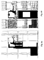
- the typical situation is that the order collector when picking up the packages remains standing on the platform (or in the cab) of the order-collection truck. However, he first has to turn through 180° from the direction of travel.
- Pallet and package data are completely identical to those for low-lifting order-collection trucks (see description of Figs. 4a and 4b).
- the order collector stands centrally in front of the pallet on the order-collection truck. He only has to turn through 90° to the left or right in order to be able to place the order-collection scoop beneath a package. Furthermore, the swinging motion towards the centre of the pallet brought along is very limited and is very easy to control. The scoop itself also only has to turn through 90°.
- the high-lifting order-collection truck (Figs. 6A and 6B) also has the extra advantage that the height of the pallet brought along can also be adjusted, so that placing the packages on the pallet is even simpler and easier.
- the order collector has to reach a long way (pallet depth 1200 mm) in order to stack the packages on the pallet.
Landscapes
- Engineering & Computer Science (AREA)
- Transportation (AREA)
- Structural Engineering (AREA)
- Mechanical Engineering (AREA)
- Civil Engineering (AREA)
- Life Sciences & Earth Sciences (AREA)
- Geology (AREA)
- Warehouses Or Storage Devices (AREA)
- Handcart (AREA)
- Forklifts And Lifting Vehicles (AREA)
Applications Claiming Priority (2)
| Application Number | Priority Date | Filing Date | Title |
|---|---|---|---|
| NL1004177 | 1996-10-02 | ||
| NL1004177A NL1004177C2 (nl) | 1996-10-02 | 1996-10-02 | Een orderverzamelhulpmiddel ten behoeve van het orderverzamelen in magazijnen met gepalletiseerde goederenopslag. |
Publications (1)
| Publication Number | Publication Date |
|---|---|
| EP0834464A1 true EP0834464A1 (de) | 1998-04-08 |
Family
ID=19763608
Family Applications (1)
| Application Number | Title | Priority Date | Filing Date |
|---|---|---|---|
| EP97202933A Withdrawn EP0834464A1 (de) | 1996-10-02 | 1997-09-26 | Vorrichtung zur Versammlung von Bestellungen in Wasserlagern mit auf Paletten gestapelten Gütern |
Country Status (5)
| Country | Link |
|---|---|
| US (1) | US5931633A (de) |
| EP (1) | EP0834464A1 (de) |
| JP (1) | JPH10120383A (de) |
| CA (1) | CA2216347A1 (de) |
| NL (2) | NL1004177C2 (de) |
Cited By (4)
| Publication number | Priority date | Publication date | Assignee | Title |
|---|---|---|---|---|
| WO2001092140A1 (en) * | 2000-05-29 | 2001-12-06 | Jacob Moses N | Sheet stack handler |
| WO2006128405A1 (de) * | 2005-06-02 | 2006-12-07 | Gebhardt Transport- Und Lagersysteme Gmbh | Hubvorrichtung |
| SE2051280A1 (en) * | 2020-11-04 | 2022-05-05 | Lifts All Ab | A lifting aid arrangement for a transport vehicle |
| EP3862144B1 (de) | 2020-02-05 | 2023-11-08 | BARRUS GmbH | Manipulator zum anordnen an einem fahrzeug sowie verfahren zum bewegen und/oder sichern eines manipulators |
Families Citing this family (7)
| Publication number | Priority date | Publication date | Assignee | Title |
|---|---|---|---|---|
| JP2000053237A (ja) * | 1998-08-07 | 2000-02-22 | Shinko Electric Co Ltd | 搬送設備 |
| US6732871B1 (en) * | 1999-09-14 | 2004-05-11 | Neil R. Flores | Cargo transport and handling device |
| DE102015210664A1 (de) * | 2015-06-11 | 2016-12-15 | Bayerische Motoren Werke Aktiengesellschaft | Vorrichtung zum kontrollierten Absenken von Lasten |
| DE102016212628A1 (de) * | 2016-07-12 | 2018-01-18 | Bayerische Motoren Werke Aktiengesellschaft | Transporteinheit sowie Verfahren zum Be- und/oder Entladen einer Transporteinheit |
| CN110615217B (zh) * | 2018-06-20 | 2025-02-21 | 北京京东乾石科技有限公司 | 无人配送车自动调节重量的方法及无人配送车 |
| CN117262554A (zh) * | 2023-09-21 | 2023-12-22 | 中国第一汽车股份有限公司 | 一种汽车侧围焊装立体夹具库传动装置 |
| IT202300026769A1 (it) * | 2023-12-15 | 2025-06-15 | Bravi Platforms S R L | Unità di prelievo di collo integrabile in una piattaforma mobile elevabile |
Citations (10)
| Publication number | Priority date | Publication date | Assignee | Title |
|---|---|---|---|---|
| US1492999A (en) * | 1922-04-10 | 1924-05-06 | Iza N Mercer | Grapple |
| US3069196A (en) * | 1961-05-29 | 1962-12-18 | Bickerstaff Inc | Apparatus for lifting stacks of building units |
| FR1435976A (fr) * | 1965-03-02 | 1966-04-22 | Perfectionnements aux dispositifs à câble pour la manutention des tôles et plaques métalliques analogues | |
| DE1506950A1 (de) * | 1967-06-30 | 1969-10-30 | Hermann Kronseder | Halbautomatische Vorrichtung zum Beladen von Paletten mit auf einer Foerderbahn ankommenden Stapeln,beispielsweise Kistenstapeln,und zum Entladen solcher Stapel von Paletten vorzugsweise auf Foerderbahnen |
| FR1587688A (de) * | 1967-08-29 | 1970-03-27 | ||
| DE2101429A1 (de) * | 1971-01-13 | 1972-08-03 | Erismann P | Hebe- und Transportvorrichtung für beladene oder unbeladene Transportpaletten |
| US3759399A (en) * | 1972-01-14 | 1973-09-18 | Fmc Corp | Adjustable, self-locking load supporting mechanism for booms |
| US4095752A (en) * | 1975-09-17 | 1978-06-20 | Societe Civile Particuliere Innovation Promotion S.C.I.P. | Motorized shovel |
| DE3446231A1 (de) * | 1983-12-21 | 1985-07-11 | Franz Grötz GmbH & Co KG Bauunternehmung, 7560 Gaggenau | Vorrichtung zum verlegen von randsteinen o.dgl. |
| DE4237058A1 (de) * | 1992-11-03 | 1994-05-05 | Rolf Schoch | Fahrbares Arbeitsgerät |
Family Cites Families (26)
| Publication number | Priority date | Publication date | Assignee | Title |
|---|---|---|---|---|
| US1826489A (en) * | 1927-03-14 | 1931-10-06 | Elwell Parker Electric Co | Industrial truck |
| US1847819A (en) * | 1931-04-01 | 1932-03-01 | American Steel & Wire Co | Hairpin hook |
| US2535961A (en) * | 1948-08-26 | 1950-12-26 | Stearns Mfg Company | Hoist or off-bearer |
| US2520564A (en) * | 1948-11-08 | 1950-08-29 | Oren L Reagle | Load holding attachment for industrial trucks |
| US2624470A (en) * | 1949-02-10 | 1953-01-06 | Herbert F Geist | Pallet handling apparatus |
| DE952746C (de) * | 1954-07-24 | 1956-11-22 | Emma Elfriede Bellmann Geb Vog | Greifer zum Foerdern und Kippen von Platten und ringfoermigem Gut, wie Blechpakete, Metallbunde od. dgl. |
| DE1084888B (de) * | 1955-12-03 | 1960-07-07 | Huet Aloysius T Van | Vorrichtung zum Laden und Entladen von Ziegelsteinen |
| US2828039A (en) * | 1956-07-20 | 1958-03-25 | Manuel E Puim | Front loading and elevating attachment for vehicles |
| US3104016A (en) * | 1957-12-16 | 1963-09-17 | Alliance Machine Co | Coil handling crane |
| US3063574A (en) * | 1959-01-21 | 1962-11-13 | Union Special Machine Co | Material handling apparatus |
| SU136871A1 (ru) * | 1960-09-27 | 1960-11-30 | С.А. Постников | Захват двухканатного типа дл штучных грузов |
| US3039810A (en) * | 1960-10-28 | 1962-06-19 | Int Harvester Co | Material handling hoist for pallets and the like |
| DE1177863B (de) * | 1962-03-23 | 1964-09-10 | Erwin Baas | Betaetigungsvorrichtung fuer die Greifzange einer von einem Front- oder Hecklader getragenen Ladegabel |
| US3258287A (en) * | 1965-03-12 | 1966-06-28 | Kelsey Hayes Co | Holding hook for hollow work stock |
| US3436116A (en) * | 1967-07-12 | 1969-04-01 | Heppenstall Co | Tiltable lifting tongs |
| DE2218579C3 (de) * | 1972-04-17 | 1982-01-07 | Schmidt, Kranz & Co Gmbh, Zweigniederlassung Maschinenbau, 3421 Zorge | Greifer für paketierte Lasten |
| US4000923A (en) * | 1975-06-26 | 1977-01-04 | Matt Baldwin | Gabion basket emplacement apparatus and method |
| SU772967A1 (ru) * | 1979-01-05 | 1980-10-23 | Центральный научно-исследовательский институт механической обработки древесины | Крановый вилочный захват дл грузов |
| US4320915A (en) * | 1980-03-24 | 1982-03-23 | Varco International, Inc. | Internal elevator |
| US4375936A (en) * | 1980-08-18 | 1983-03-08 | Harnischfeger Corporation | Stacker crane for movement of coils |
| US4708574A (en) * | 1985-07-05 | 1987-11-24 | D. W. Zimmerman Mfg., Inc. | Apparatus for handling objects |
| US4722106A (en) * | 1986-04-16 | 1988-02-02 | Stow-A-Crane Division | Beehive lifting device |
| US4797059A (en) * | 1986-11-07 | 1989-01-10 | General Motors Corporation | Seat handling fixture |
| IT1222730B (it) * | 1987-09-25 | 1990-09-12 | Savio Spa | Metodo ed apparecchio per la rimozione di bobine di filato e loro deposito in un carrello a pioli |
| DE8808399U1 (de) * | 1988-06-30 | 1988-09-01 | VETTER Fördertechnik GmbH, 5900 Siegen | Ladegabel |
| DE9003924U1 (de) * | 1990-04-03 | 1990-08-09 | Lemm, Dieter, 4050 Mönchengladbach | Vorrichtung zum Aufnehmen und Manipulieren von zu Rollen mit Zentralöffnung gewickeltem Gut |
-
1996
- 1996-10-02 NL NL1004177A patent/NL1004177C2/nl not_active IP Right Cessation
-
1997
- 1997-09-23 CA CA002216347A patent/CA2216347A1/en not_active Abandoned
- 1997-09-26 US US08/938,445 patent/US5931633A/en not_active Expired - Fee Related
- 1997-09-26 EP EP97202933A patent/EP0834464A1/de not_active Withdrawn
- 1997-09-30 NL NL1007185A patent/NL1007185C1/nl not_active IP Right Cessation
- 1997-10-02 JP JP9270137A patent/JPH10120383A/ja active Pending
Patent Citations (10)
| Publication number | Priority date | Publication date | Assignee | Title |
|---|---|---|---|---|
| US1492999A (en) * | 1922-04-10 | 1924-05-06 | Iza N Mercer | Grapple |
| US3069196A (en) * | 1961-05-29 | 1962-12-18 | Bickerstaff Inc | Apparatus for lifting stacks of building units |
| FR1435976A (fr) * | 1965-03-02 | 1966-04-22 | Perfectionnements aux dispositifs à câble pour la manutention des tôles et plaques métalliques analogues | |
| DE1506950A1 (de) * | 1967-06-30 | 1969-10-30 | Hermann Kronseder | Halbautomatische Vorrichtung zum Beladen von Paletten mit auf einer Foerderbahn ankommenden Stapeln,beispielsweise Kistenstapeln,und zum Entladen solcher Stapel von Paletten vorzugsweise auf Foerderbahnen |
| FR1587688A (de) * | 1967-08-29 | 1970-03-27 | ||
| DE2101429A1 (de) * | 1971-01-13 | 1972-08-03 | Erismann P | Hebe- und Transportvorrichtung für beladene oder unbeladene Transportpaletten |
| US3759399A (en) * | 1972-01-14 | 1973-09-18 | Fmc Corp | Adjustable, self-locking load supporting mechanism for booms |
| US4095752A (en) * | 1975-09-17 | 1978-06-20 | Societe Civile Particuliere Innovation Promotion S.C.I.P. | Motorized shovel |
| DE3446231A1 (de) * | 1983-12-21 | 1985-07-11 | Franz Grötz GmbH & Co KG Bauunternehmung, 7560 Gaggenau | Vorrichtung zum verlegen von randsteinen o.dgl. |
| DE4237058A1 (de) * | 1992-11-03 | 1994-05-05 | Rolf Schoch | Fahrbares Arbeitsgerät |
Cited By (4)
| Publication number | Priority date | Publication date | Assignee | Title |
|---|---|---|---|---|
| WO2001092140A1 (en) * | 2000-05-29 | 2001-12-06 | Jacob Moses N | Sheet stack handler |
| WO2006128405A1 (de) * | 2005-06-02 | 2006-12-07 | Gebhardt Transport- Und Lagersysteme Gmbh | Hubvorrichtung |
| EP3862144B1 (de) | 2020-02-05 | 2023-11-08 | BARRUS GmbH | Manipulator zum anordnen an einem fahrzeug sowie verfahren zum bewegen und/oder sichern eines manipulators |
| SE2051280A1 (en) * | 2020-11-04 | 2022-05-05 | Lifts All Ab | A lifting aid arrangement for a transport vehicle |
Also Published As
| Publication number | Publication date |
|---|---|
| US5931633A (en) | 1999-08-03 |
| NL1007185C1 (nl) | 1998-04-06 |
| JPH10120383A (ja) | 1998-05-12 |
| CA2216347A1 (en) | 1998-04-02 |
| NL1004177C2 (nl) | 1998-04-06 |
Similar Documents
| Publication | Publication Date | Title |
|---|---|---|
| US5931633A (en) | Order-collection appliance for collecting orders in warehouses with palletized storage of goods | |
| US5350270A (en) | Pickface conveyor | |
| US5362197A (en) | Automatic storage and retrieval system | |
| US6533096B2 (en) | Extendable gravity loader | |
| US5050833A (en) | Angled roller device for multiple garment hanger rope-sling | |
| EP4363353B1 (de) | Zugangsstation für ein automatisiertes regalbedienungssystem | |
| US4458786A (en) | Fork-lift truck with synchronized variable travelling and lifting surfaces | |
| US5277439A (en) | Hand truck | |
| EP2726385A1 (de) | Lagerungssystem mit vertikalem hub und verfahren zum betrieb eines hubs | |
| US6561528B2 (en) | Wheeled device | |
| US9051086B2 (en) | Ice tote having a hanging device | |
| WO2011145995A1 (en) | Lift for shopping trolley | |
| WO2014011035A2 (en) | Harvest transport vehicle | |
| EP2055654B1 (de) | Vorrichtung zur Entladung von Kisten- und Hängebestand | |
| AU676141B2 (en) | Method and apparatus for loading and unloading of goods in an aircraft hold | |
| CN216685937U (zh) | 一种仓库拣货车 | |
| US20030230924A1 (en) | E-Z lift : ergonomic back saving motorized unloader for utility/laundry carts | |
| US3826512A (en) | Cart | |
| US7192236B1 (en) | Shelf stacking machine | |
| US4303365A (en) | Continuous chain stacker/unstacker | |
| US7014198B2 (en) | Low profile cart and automatic unloading system | |
| EP3105167B1 (de) | Hebevorrichtung für einkaufswagen | |
| JP4239920B2 (ja) | 農作物収穫機 | |
| US5030055A (en) | Physically integrated manufacturing and materials handling system | |
| EP0480994B1 (de) | Vorrichtung und verfahren zur handhabung von stapelbaren kasten |
Legal Events
| Date | Code | Title | Description |
|---|---|---|---|
| PUAI | Public reference made under article 153(3) epc to a published international application that has entered the european phase |
Free format text: ORIGINAL CODE: 0009012 |
|
| AK | Designated contracting states |
Kind code of ref document: A1 Designated state(s): AT BE CH DE DK ES FR GB IT LI NL SE |
|
| 17P | Request for examination filed |
Effective date: 19981007 |
|
| AKX | Designation fees paid |
Free format text: AT BE CH DE DK ES FI FR GB GR IE LI |
|
| RBV | Designated contracting states (corrected) |
Designated state(s): AT BE CH DE DK ES FI FR GB GR IE LI |
|
| RBV | Designated contracting states (corrected) |
Designated state(s): AT BE CH DE DK ES FR GB IT LI NL SE |
|
| 17Q | First examination report despatched |
Effective date: 20010827 |
|
| GRAH | Despatch of communication of intention to grant a patent |
Free format text: ORIGINAL CODE: EPIDOS IGRA |
|
| STAA | Information on the status of an ep patent application or granted ep patent |
Free format text: STATUS: THE APPLICATION IS DEEMED TO BE WITHDRAWN |
|
| 18D | Application deemed to be withdrawn |
Effective date: 20030304 |