EP0834647B1 - Ventiltriebvorrichtung für Brennkraftmaschine - Google Patents
Ventiltriebvorrichtung für Brennkraftmaschine Download PDFInfo
- Publication number
- EP0834647B1 EP0834647B1 EP97117316A EP97117316A EP0834647B1 EP 0834647 B1 EP0834647 B1 EP 0834647B1 EP 97117316 A EP97117316 A EP 97117316A EP 97117316 A EP97117316 A EP 97117316A EP 0834647 B1 EP0834647 B1 EP 0834647B1
- Authority
- EP
- European Patent Office
- Prior art keywords
- rocker arm
- valve
- operating mechanism
- set forth
- cam
- Prior art date
- Legal status (The legal status is an assumption and is not a legal conclusion. Google has not performed a legal analysis and makes no representation as to the accuracy of the status listed.)
- Expired - Lifetime
Links
- 230000007246 mechanism Effects 0.000 claims description 44
- 238000010168 coupling process Methods 0.000 claims description 17
- 230000008878 coupling Effects 0.000 claims description 16
- 238000005859 coupling reaction Methods 0.000 claims description 16
- 238000002485 combustion reaction Methods 0.000 claims description 5
- 238000010276 construction Methods 0.000 description 4
- 230000000712 assembly Effects 0.000 description 3
- 238000000429 assembly Methods 0.000 description 3
- 230000006835 compression Effects 0.000 description 3
- 238000007906 compression Methods 0.000 description 3
- 238000011217 control strategy Methods 0.000 description 2
- 238000010348 incorporation Methods 0.000 description 2
- 230000006698 induction Effects 0.000 description 2
- 230000000694 effects Effects 0.000 description 1
- 239000012530 fluid Substances 0.000 description 1
Images








Classifications
-
- F—MECHANICAL ENGINEERING; LIGHTING; HEATING; WEAPONS; BLASTING
- F01—MACHINES OR ENGINES IN GENERAL; ENGINE PLANTS IN GENERAL; STEAM ENGINES
- F01L—CYCLICALLY OPERATING VALVES FOR MACHINES OR ENGINES
- F01L1/00—Valve-gear or valve arrangements, e.g. lift-valve gear
- F01L1/26—Valve-gear or valve arrangements, e.g. lift-valve gear characterised by the provision of two or more valves operated simultaneously by same transmitting-gear; peculiar to machines or engines with more than two lift-valves per cylinder
- F01L1/267—Valve-gear or valve arrangements, e.g. lift-valve gear characterised by the provision of two or more valves operated simultaneously by same transmitting-gear; peculiar to machines or engines with more than two lift-valves per cylinder with means for varying the timing or the lift of the valves
Definitions
- variable valve timing and variable valve lift have been proposed for achieving either or both of the variable valve timing and variable valve lift. For the most part, however, they are fairly complex and add significantly to the complexity of the valve train.
- DE-A-36 13 945 and corresponding US-A-4 726 332 disclose a variable valve mechanism for an engine including a first rocker arm engaged at one end with the valve tappet and at the other end with a low speed profile cam, and a second rocker arm engaged with a high speed profile cam.
- a locking device is provided on the second rocker arm to releasably lock the second rocker arm on the first rocker arm under a high speed engine operation.
- This invention is adapted to be embodied in the valve actuating mechanism for operating a single poppet valve of an engine through cooperation with the stem thereof.
- the valve operating mechanism is comprised of a single cam shaft having a pair of adjacent cams.
- a pair of adjacent, pivotally supported rocker arms each cooperate with a respective one of the cams.
- a first of the rocker arms has an operating portion for direct cooperation with the valve stem for operating the valve.
- Means provide a selective coupling of the second rocker arm to the first rocker arm for effecting actuation of the valve through the first rocker arm.
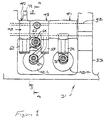
- Figure 1 is a top plan view looking at the valve actuating mechanism associated with a single cylinder of an internal combustion engine constructed in accordance with a first embodiment of the invention, with the cam cover for the engine removed.
- Figure 2 is an exploded view showing the same components illustrated in Figure 1 but illustrating only the cam shaft and the rocker arms associated therewith.
- Figure 3 is a cross-sectional view taken along the line 3-3 of Figure 1 and illustrates one of the rocker arms and its association with the cam shaft.
- Figure 4 is a cross-sectional view taken along the line 4-4 of Figure 1 and shows the valve in its closed position.
- Figure 5 is a cross-sectional view, in part similar to Figure 4, and shows the valve in its open position when opened by the first rocker arm.
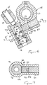
- Figure 6 is an enlarged cross-sectional view taken along the same plane as Figures 4 and 5, and shows the same condition as in Figure 4, i.e., with the valve closed.
- Figure 7 is a cross-sectional view taken along the line 7-7 of Figure 6.
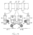
- Figure 15 is a view, in part similar to Figure 1, and shows another embodiment of the invention where both valves of the same cylinder are operated by variable valve actuating mechanisms.
- Figure 16 is a partially exploded view, in part similar to Figure 2, but shows the cam shaft and rocker arms of this embodiment.
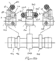
- Figure 18 is an exploded view, in part similar to Figures 2 and 16, but shows the cam shaft and rocker arms for this embodiment.
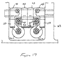
- Figure 19 is a top plan view, in part similar to Figures 1, 15 and 17, and shows yet another embodiment of the invention wherein both valves associated with the same cylinder has a variable valve actuating mechanism but, in this embodiment, sharing one of the rocker arms.
- Figure 21 is a cross-sectional view, in part similar to Figure 3, but shows another type of biasing arrangement for the second rocker arm.
- a portion of a cylinder head assembly of an internal combustion engine is illustrated and is identified generally by the reference numeral 31. Only a portion of the engine is illustrated and specifically the cylinder head thereof because the invention deals, as aforenoted, with a valve actuating mechanism for engines. Therefore, when any details of the construction of the engine are not illustrated, they may be considered to be conventional. Those skilled in the art will be able to determine from the following description how the invention can be utilized with a wide variety of engines.
- each cylinder of the engine is served by a pair of intake passages 35 that terminate in valve seats 36 which are valved by poppet-type intake valves, indicated generally by the reference numeral 37.
- These valves 37 have head portions 38 that cooperate with the valve seats 36 and stem portions 39 that are slidably supported in valve guides 41 affixed to the cylinder head member 32.
- keeper retainer assemblies 42 retain spring assemblies 43 that act between the keeper retainer assemblies 42 and the cylinder head for biasing the valves 37 to their closed positions, as is well-known in this art.
- the rocker arm 49 has an outwardly extending arm which forms an integral follower 63 that is engaged by the cam lobe 46.
- the cam lobe 46 is of a larger lift and larger diameter than that of the cam lobe 45.
- this cam lobe 46 may also be configured to provide slightly different timing through its cooperation with the first rocker arm 48.
- the spring arrangement includes an outer cylinder member 68 which defines a bore in which a sliding biasing member 69 is provided.
- the sliding biasing member 69 is biased by a coil compression spring 71 into engagement with a further follower surface 72 formed on a portion of the rocker arm 49 that extends in somewhat diametrical opposition to the portion that forms the follower surface 63.
- the spring 71 acting through the biasing member 69 and rocker arm surface 72 will maintain the rocker arm follower 63 in engagement with the cam lobe 46.
- the lower end of the bore 74 is partially closed by a cap 78 which forms an engagement for a biasing spring 79 that acts on the lower end of the coupling plunger member 76.
- This spring 79 keeps the coupling plunger member 76 and specifically its surface 77 in constant engagement with the adjusting screw 65. It should be apparent, however, that if desired, some clearance may be maintained in this gap depending upon how the valve operation is to be accomplished. Also in some views the position of the plunger member 76 in the bore may not be the true position depending upon the lift characteristics of the respective cams 45 and 46 and specifically that of their lobes.
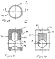
- the coupling plunger member 76 is formed with a bore 81 that extends from a flat surface 82 formed in a side thereof by a machined recess 83. Received within the bore 81 is a return spring arrangement that is comprised of a pair of end caps 85 and 86 that are urged apart by a coil compression spring 87.
- this compression spring 87 causes the retaining member 86 to be urged to a position where a flat surface of it is coextensive with the surface 82. Under this condition the surface 82 is engaged by a slidable locking member 88.
- the locking member 88 is slidably supported within a bore 89 that extends through the rocker arm 48 below its journal on the rocker arm shaft 51. The outer end of this bore 89 is closed by a closure plug 91 and in the uncoupled state, the locking member 88 is abuttingly engaged with this closure plug 91.
- a gap 92 is provided between it and the end closure 91.
- This gap communicates with an oil control passage 93 that extends through the rocker arm shaft 51 and rocker arm 48.
- the rocker arm shaft 51 is hollow and hydraulic fluid pressure may be exerted selectively through this passage 73 to the area 92 in accordance with a desired control strategy.
- One such strategy will be described later by reference to the embodiment of Figure 14.
- rocker arm 51 and cam lobe 47 that operate the remaining intake valve which does not have its lift varied in this embodiment.
- the rocker arm 51 has a follower surface 94 that is engaged by the cam lobe 47.
- An adjusting screw 95 carried at the tip of this rocker arm cooperates with the stem of this valve to operate it in a normal manner.
- Varying types of lift arrangements may be employed and different lift ratios and/or valve timing between the non-variable actuated valve and the variable actuated valve. That is the lift and/or timing of the valve operated by the cam 47 may be the same as that provided by either of the cams 45 or 46 associated with the other valve or different from either of them.
- FIG 14 is a view that shows one way in which this mechanism may operate. This view shows the induction system schematically and it now will be described by reference to that Figure.
- the normally or non-variably actuated valve is indicated by the reference numeral 37-2, while the variably actuated valve is indicated by the reference numeral 37-1.
- the intake passages 35 associated therewith have also been indicated by the same suffixes, i.e., 35-2 and 35-1.
- an air inlet device draws atmospheric air through an inlet opening 102 in which a manually actuated throttle control valve 103 is positioned.
- the air inlet device 101 forms a plenum chamber 104 that communicates with the runners 35-1 and 35-2 of each cylinder.
- a control valve 105 is provided in the runner 35-2 and is operated by a servo motor 106 under the control of an ECU, indicated generally by the reference numeral 107.
- the intake valve 37-1 and its operation is adjusted to optimize primarily the low and mid-range performance of the engine.
- the cam lobe 45 and rocker arm 48 can be tailored for optimum performance under low-speed and low-mid range running.
- the cam lobe 46 and rocker arm 49 are coupled for a higher range of operation and may provide a substantially greater lift so as to improve the performance under higher speeds and loads.
- the ECU effects opening of the control valve 105 by the servo motor 106.
- the engine can provide very good performance under a wide variety of speeds and loads due to the use of the variable valve actuating mechanism and the control valve 105.
- the adjusting screw 65 In order to permit a compact assembly, obviously the adjusting screw 65 must be configured in relation to the cam lobes and specifically the cam lobe 45, so as to not present any interference.
- Figures 15 and 16 show another embodiment of the invention wherein both of the intake valves 37-1 and 37-2 are provided with a variable valve actuating mechanism.
- the cam shaft is provided with, in addition to, the lobes 45 and 46, for actuating the first intake valve 37-1, with additional lobes 151 and 152 for operating the rocker arms 48 and 49 associated with the remaining valve 37-2.
- rocker arms 48 and 49 associated with the second intake valve 37-2 are mirror images so as to permit the two rocker arms 48 to be positioned next to each other and the other two rocker arms to be spaced more widely. With this type of arrangement, as shown, the initial lift for the valve 37-2 is less than that of the valve 37-1 but the maximum lift provided by the cam lobes 46 and 152 can be the same.
- FIGS 19 and 20 show another embodiment wherein the second rocker arms for the two valves are integrated into a single rocker arm. Since that is the only difference between this embodiment and that shown in Figures 17 and 18, components which are the same are identified by the same reference numerals and will not be described again, except insofar as is necessary to understand the construction and operation of this embodiment.
- a single second rocker arm 201 for each of the valves 37-1 and 37-2 is provided .
- This rocker arm 201 has a single follower surface 202 that is engaged by a single cam lobe 203.
- This rocker arm has a pair of bosses 204 and 205 each of which carries a respective adjusting screw 206 and 207. These adjusting screws actuate the connecting system of the adjacent rocker arms 48, in the manner that has already been described.
- the arrangement can be further simplified.
- the operation of the second rocker arm 201 on each valve then must be the same. Different lift characteristics can be provided for the operation of the valves 37-1 and 37-2 and in this embodiment the lift of 37-1 is greater than that of 37-2 before the rocker arm 201 actuates both valves.
- Figures 21 and 22 show both the incorporation of the variable valve actuating mechanism for all valves of the engine and also shows a different biassing arrangement for the second rocker arms. Since this is the only main difference, components which are the same or substantially the same have been identified by the same reference numerals.
- the second rocker arms 48 have, on the opposite side from their follower surfaces 59, a protruding portion 251 that is engaged by a spring return mechanism which is in essence the same as that employed in and shown in detail in Figure 3.
- this return mechanism 67 is mounted directly in the cylinder head member 32 rather than on the cam carrier 33. In all other regards, this embodiment is the same and thus, further description of it is not believed to be necessary to permit those skilled in the art to practice the invention.
Landscapes
- Engineering & Computer Science (AREA)
- Mechanical Engineering (AREA)
- General Engineering & Computer Science (AREA)
- Valve Device For Special Equipments (AREA)
- Valve-Gear Or Valve Arrangements (AREA)
Claims (20)
- Ventiltriebmechanismus zum Steuern eines einzelnen Tellerventils (37) eines Motors durch Zusammenwirken mit dessen Schaft (39), wobei der Ventiltriebmechanismus aufweist: eine einzelne Nockenwelle (44) mit einem Paar benachbarter Nocken (45, 46), ein Paar benachbarter, schwenkbar gelagerter Kipphebel (48, 49), wobei jeder der Kipphebel von einem jeweiligen der Nocken betätigt wird, wobei ein erster der Kipphebel (48) einen Betätigungsabschnitt für direkten Eingriff mit dem Ventilschaft (39) zur direkten Steuerung des Ventils (37) hat, und eine Einrichtung (73) zum selektiven Koppeln des zweiten der Kipphebel (49) mit dem ersten Kipphebel (48) zur Ausführung der Betätigung des Ventils (37) von dort über den ersten Kipphebel (48) durch den Nocken (46), der dem zweiten Kipphebel (49) zugeordnet ist, der eine Betätigungseinrichtung (65) aufweist, die vom zweiten Kipphebel (49) getragen wird und mit einer Koppeleinrichtung eingriffsfähig ist, die vom ersten Kipphebel (48) getragen wird, zur Betätigung des ersten Kipphebels, wobei die Koppeleinrichtung einen Kolben (76) aufweist, der gleitfähig in einer Bohrung (75) gelagert ist, die im ersten Kipphebel (48) ausgebildet ist, und wobei der Kolben (76) mit der Betätigungseinrichtung (65) des zweiten Kipphebels (49) in Eingriff ist, gekennzeichnet durch einen hydraulisch betätigten Stift, der im ersten Kipphebel (48) gleitfähig gelagert ist und eingriffsfähig ist mit einer Bohrung (81), die im Kolben (76) ausgebildet ist, zum Verriegeln des Kolbens (76) gegen eine Gleitbewegung in der Bohrung (81) und einer hohlen Kipphebelwelle (52), wobei Hydraulikdruck über die Kipphebelwelle zum Stift (88) übertragen wird.
- Ventiltriebmechanismus nach Anspruch 1, wobei beide Kipphebel (48, 49) auf der gleichen Kipphebelwelle (52) gelagert sind.
- Ventiltriebmechanismus nach Anspruch 1 oder 2, wobei der erste und der zweite Nocken (45, 46) und der erste und der zweite Kipphebel (48, 49) einen anderen Hub für das betätigte Ventil (37) bereitstellen.
- Ventiltriebmechanismus nach Anspruch 3, wobei der Hub, der vom zweiten Nocken (46) und vom zweiten Kipphebel (49) bereitgestellt wird, größer ist als der, der vom ersten Nocken (45) und vom ersten Kipphebel (48) bereitgestellt wird.
- Ventiltriebmechanismus nach Anspruch 2, wobei das Ventil (37) eine Feder (79) hat, die ihr zugeordnet ist, zum Ineingriffhalten des ersten Kipphebels (48) mit dem ersten Nocken (45), und ferner mit einer getrennten Vorspannungsfeder (71) zum Ineingriffdrücken des zweiten Kipphebels (49) mit dem zweiten Nocken (46).
- Ventiltriebmechanismus nach Anspruch 5, wobei die zweite Feder (71) mit einem Arm (72) des zweiten Kipphebels (49) in Eingriff ist, der von seinem Betätigungsabschnitt (63) beabstandet ist, und wobei die Feder (71) gegen das Motorgehäuse (32) drückt.
- Ventiltriebmechanismus nach einem der Ansprüche 1 bis 6, wobei ein zweites Tellerventil (37-2) zur Bedienung der gleichen Brennkammer des Motors vorgesehen ist und wobei das zweite Tellerventil (37-2) an das ersterwähnte Tellerventil (37-1) angrenzt.
- Ventiltriebmechanismus nach Anspruch 7, wobei beide Tellerventile (37-1, 37-2) mit dem Brennraum in Verbindung stehen.
- Ventiltriebmechanismus nach Anspruch 8, wobei das zweite Tellerventil (37-2) von einem dritten Nocken (47) über einen dritten Kipphebel (51) betätigt wird.
- Ventiltriebmechanismus nach Anspruch 9, wobei alle Kipphebel (48, 49, 51) auf der gleichen Kipphebelwelle (52) gelagert sind.
- Ventiltriebmechanismus nach Anspruch 10, wobei die Ventile (37-1, 37-2) beide Einlaßventile sind.
- Ventiltriebmechanismus nach Anspruch 11, wobei das ersten Ventil (37-1) vom ersten Nocken (45) und vom ersten Kipphebel (48) mit einem kleineren Hub und vom zweiten Nocken (46) und vom zweiten Kipphebel (49) über den ersten Kipphebel (48) mit einem größeren Hub betätigt wird und wobei der dritte Nocken (47) und der dritte Kipphebel (51) einen Hub für das zweite Ventil (37-2) bereitstellen, der größer ist als der des ersten Nocken (45) und des ersten Kipphebels (48) am ersten Ventil (37-1).
- Ventiltriebmechanismus nach Anspruch 12, wobei getrennte Einlaßkanäle (35-1, 35-2) die Einlaßventile (37-1, 37-2) bedienen, und ferner mit einem Steuerventil (105) im Einlaßkanal (35-2), der das zweite Ventil (37-2) bedient, das als Antwort auf Motorlaufbedingungen gesteuert wird und nur unter hohen Drehzahl- und hohen Lastbedingungen geöffnet wird.
- Ventiltriebmechanismus nach Anspruch 7, wobei das zweite Ventil (37-2) vom ersten und zweiten Kipphebel (48, 49) gesteuert wird, die jeweils mit einer jeweiligen Nockenerhebung (45, 46) zusammenwirken, um einen anderen Hub bereitzustellen, und ferner mit einer Einrichtung zum selektiven Koppeln des ersten und zweiten Kipphebels (48, 49) miteinander, die dem zweiten Ventil (37-2) zugeordnet sind, zum Ändern des Hubs des zweiten Ventils (37-2).
- Ventiltriebmechanismus nach Anspruch 14, wobei die ersten Kipphebel (48, 48) für die beiden Ventile (37-1, 37-2) auf der Kipphebelwelle (52) nebeneinander angeordnet sind.
- Ventiltriebmechanismus nach Anspruch 14 oder 15, wobei die zweiten Kipphebel (49, 49) auf der gleichen Kipphebelwelle (52) nebeneinander angeordnet sind.
- Ventiltriebmechanismus nach Anspruch 16, wobei der Hub, der vom ersten Nocken (45) und vom ersten Kipphebel (48) eines der Ventile (37-1, 37-2) bereitgestellt wird, sich von dem unterscheidet, der vom ersten Nocken (45) und vom ersten Kipphebel (48) des anderen Ventils (37-2, 37-1) bereitgestellt wird.
- Ventiltriebmechanismus nach einem der Ansprüche 14 bis 17, wobei einer der Kipphebel für jedes der Ventile ein gemeinsamer Kipphebel (201) ist, der beide Ventile (37-1, 37-2) betätigen kann.
- Ventiltriebmechanismus nach Anspruch 18, wobei der eine Kipphebel (201) der zweite Kipphebel ist.
- Ventiltriebmechanismus nach Anspruch 19, wobei der eine Kipphebel (201) mit einem einzelnen zweiten Nocken (203) zusammenwirkt.
Applications Claiming Priority (9)
| Application Number | Priority Date | Filing Date | Title |
|---|---|---|---|
| JP266071/96 | 1996-10-07 | ||
| JP26607196 | 1996-10-07 | ||
| JP26608096 | 1996-10-07 | ||
| JP26607196 | 1996-10-07 | ||
| JP266080/96 | 1996-10-07 | ||
| JP26608096 | 1996-10-07 | ||
| JP8277692A JPH10121928A (ja) | 1996-10-21 | 1996-10-21 | 内燃機関の動弁装置 |
| JP27769296 | 1996-10-21 | ||
| JP277692/96 | 1996-10-21 |
Publications (2)
| Publication Number | Publication Date |
|---|---|
| EP0834647A1 EP0834647A1 (de) | 1998-04-08 |
| EP0834647B1 true EP0834647B1 (de) | 2002-07-03 |
Family
ID=27335430
Family Applications (1)
| Application Number | Title | Priority Date | Filing Date |
|---|---|---|---|
| EP97117316A Expired - Lifetime EP0834647B1 (de) | 1996-10-07 | 1997-10-07 | Ventiltriebvorrichtung für Brennkraftmaschine |
Country Status (3)
| Country | Link |
|---|---|
| US (1) | US5924396A (de) |
| EP (1) | EP0834647B1 (de) |
| DE (1) | DE69713702T2 (de) |
Families Citing this family (18)
| Publication number | Priority date | Publication date | Assignee | Title |
|---|---|---|---|---|
| US6053135A (en) * | 1997-10-07 | 2000-04-25 | Yamaha Hatsudoki Kabushiki Kaisha | Variable valve timing mechanism |
| DE69805382T2 (de) | 1997-10-07 | 2002-11-07 | Yamaha Hatsudoki K.K., Iwata | Variable Ventilsteuervorrichtung |
| US6092497A (en) * | 1997-10-30 | 2000-07-25 | Eaton Corporation | Electromechanical latching rocker arm valve deactivator |
| US6705264B2 (en) | 1998-12-24 | 2004-03-16 | Yamaha Marine Kabushiki Kaisha | Valve control for outboard motor engine |
| US6418904B2 (en) | 2000-04-03 | 2002-07-16 | Daimlerchrysler Corporation | Pulse drive valve deactivator |
| JP2001342812A (ja) | 2000-05-31 | 2001-12-14 | Sanshin Ind Co Ltd | 船外機用4サイクルエンジン |
| US6910450B2 (en) * | 2000-05-31 | 2005-06-28 | Yamaha Marine Kabushiki Kaisha | Variable valve timing structure for outboard motor engine |
| JP2001342919A (ja) | 2000-05-31 | 2001-12-14 | Sanshin Ind Co Ltd | 船外機用4サイクルエンジン |
| US7273026B2 (en) | 2002-10-18 | 2007-09-25 | Maclean-Fogg Company | Roller follower body |
| US7028654B2 (en) | 2002-10-18 | 2006-04-18 | The Maclean-Fogg Company | Metering socket |
| US6871622B2 (en) | 2002-10-18 | 2005-03-29 | Maclean-Fogg Company | Leakdown plunger |
| US7128034B2 (en) | 2002-10-18 | 2006-10-31 | Maclean-Fogg Company | Valve lifter body |
| US7191745B2 (en) | 2002-10-18 | 2007-03-20 | Maclean-Fogg Company | Valve operating assembly |
| GB2395521A (en) * | 2002-11-23 | 2004-05-26 | Mechadyne Plc | Engine with variable valve mechanism |
| US20040244751A1 (en) * | 2003-06-03 | 2004-12-09 | Falkowski Alan G. | Deactivating valve lifter |
| US7040265B2 (en) * | 2003-06-03 | 2006-05-09 | Daimlerchrysler Corporation | Multiple displacement system for an engine |
| CN100334332C (zh) * | 2003-06-17 | 2007-08-29 | 本田技研工业株式会社 | 用于内燃机的阀组 |
| WO2015175239A1 (en) | 2014-05-15 | 2015-11-19 | Borgwarner Inc. | Latching solenoid for engine management |
Family Cites Families (15)
| Publication number | Priority date | Publication date | Assignee | Title |
|---|---|---|---|---|
| DE3239941A1 (de) * | 1982-10-28 | 1984-05-03 | Volkswagenwerk Ag, 3180 Wolfsburg | Vorrichtung zur abschaltung des ventiltriebes einer brennkraftmaschine |
| DE3613945A1 (de) * | 1985-04-26 | 1986-10-30 | Mazda Motor Corp., Hiroshima | Veraenderbarer ventilmechanismus fuer verbrennungsmaschinen |
| JPS61175206A (ja) * | 1985-07-23 | 1986-08-06 | Mazda Motor Corp | エンジンの弁作動装置 |
| US4887563A (en) * | 1986-10-16 | 1989-12-19 | Honda Giken Kogyo Kabushiki Kaisha | Valve operating apparatus for an internal combustion engine |
| DE3814835A1 (de) * | 1987-05-20 | 1988-12-01 | Volkswagen Ag | Brennkraftmaschine mit zumindest zwei einlassventilen je brennraum |
| JP2779429B2 (ja) * | 1989-09-06 | 1998-07-23 | 株式会社オティックス | 動弁機構のバルブタイミング・リフト量可変機構 |
| US5251586A (en) * | 1991-03-29 | 1993-10-12 | Fuji Jukogyo Kabushiki Kaisha | Valve mechanism for an internal combustion engine |
| US5239952A (en) * | 1991-11-08 | 1993-08-31 | Atsugi Unisia Corporation | Valve actuating apparatus |
| JP2809005B2 (ja) * | 1992-09-17 | 1998-10-08 | 日産自動車株式会社 | 内燃機関の可変動弁装置 |
| JP2762216B2 (ja) * | 1993-09-28 | 1998-06-04 | 本田技研工業株式会社 | 内燃機関 |
| JP2890236B2 (ja) * | 1994-02-28 | 1999-05-10 | 本田技研工業株式会社 | 内燃機関の動弁制御装置 |
| JPH0874533A (ja) * | 1994-09-02 | 1996-03-19 | Nissan Motor Co Ltd | 内燃機関の動弁装置 |
| JP3319896B2 (ja) * | 1994-12-21 | 2002-09-03 | 株式会社ユニシアジェックス | エンジンの弁作動装置 |
| JP3319920B2 (ja) * | 1995-10-12 | 2002-09-03 | 株式会社ユニシアジェックス | エンジンの弁作動装置 |
| US5651336A (en) * | 1995-12-26 | 1997-07-29 | Chrysler Corporation | Variable valve timing and lift mechanism |
-
1997
- 1997-10-07 DE DE69713702T patent/DE69713702T2/de not_active Expired - Lifetime
- 1997-10-07 EP EP97117316A patent/EP0834647B1/de not_active Expired - Lifetime
- 1997-10-07 US US08/946,047 patent/US5924396A/en not_active Expired - Fee Related
Also Published As
| Publication number | Publication date |
|---|---|
| DE69713702T2 (de) | 2003-03-13 |
| EP0834647A1 (de) | 1998-04-08 |
| DE69713702D1 (de) | 2002-08-08 |
| US5924396A (en) | 1999-07-20 |
Similar Documents
| Publication | Publication Date | Title |
|---|---|---|
| US5924396A (en) | Engine valve actuating system | |
| CA1274132A (en) | Valve operating mechanism for internal combustion engine | |
| EP0420159B1 (de) | Kipphebelanordnung für verstellbaren Ventilantrieb in einer Brennkraftmaschine | |
| EP0703351B1 (de) | Ventilsteuerungsvorrichtung für mehrzylindrige Brennkraftmaschine | |
| US6354254B1 (en) | Exhaust and intake rocker arm assemblies for modifying valve lift and timing during positive power | |
| US4790274A (en) | Valve operating mechanism for internal combustion engine | |
| US5046462A (en) | Rocker arm arrangement for variable valve timing type internal combustion engine valve train | |
| US5785017A (en) | Variable valve timing mechanism | |
| CA1284069C (en) | Valve operating mechanism for internal combustion engine | |
| US6343581B2 (en) | Variable valve timing and lift structure for four cycle engine | |
| US4741297A (en) | Valve operating mechanism for internal combustion engine | |
| JPS60113007A (ja) | 内燃機関の吸・排気弁制御装置 | |
| JP2000045738A (ja) | 圧縮エンジンブレ―キ装置 | |
| US5752479A (en) | Valve operating mechanism for 4-cycle engine | |
| US6053135A (en) | Variable valve timing mechanism | |
| US4572117A (en) | Valve arrangement for an internal combustion engine | |
| US6481398B2 (en) | High-low speed range switching type valve mechanism for internal combustion engine | |
| EP0519494B1 (de) | Ventilantriebmechanismus für Brennkraftmaschine | |
| EP0908604B1 (de) | Variable Ventilsteuervorrichtung | |
| JPH0346642B2 (de) | ||
| JPH04284109A (ja) | エンジンの弁作動装置 | |
| US6964252B2 (en) | Valve lifter for internal combustion engine | |
| JPH05312014A (ja) | 内燃機関の可変動弁装置 | |
| JPH0239608B2 (de) | ||
| JP2547143Y2 (ja) | エンジンの弁作動装置 |
Legal Events
| Date | Code | Title | Description |
|---|---|---|---|
| PUAI | Public reference made under article 153(3) epc to a published international application that has entered the european phase |
Free format text: ORIGINAL CODE: 0009012 |
|
| AK | Designated contracting states |
Kind code of ref document: A1 Designated state(s): DE FR GB IT |
|
| AX | Request for extension of the european patent |
Free format text: AL;LT;LV;RO;SI |
|
| 17P | Request for examination filed |
Effective date: 19981007 |
|
| AKX | Designation fees paid |
Free format text: DE FR GB IT |
|
| RBV | Designated contracting states (corrected) |
Designated state(s): DE FR GB IT |
|
| 17Q | First examination report despatched |
Effective date: 19990610 |
|
| GRAG | Despatch of communication of intention to grant |
Free format text: ORIGINAL CODE: EPIDOS AGRA |
|
| GRAG | Despatch of communication of intention to grant |
Free format text: ORIGINAL CODE: EPIDOS AGRA |
|
| GRAG | Despatch of communication of intention to grant |
Free format text: ORIGINAL CODE: EPIDOS AGRA |
|
| GRAH | Despatch of communication of intention to grant a patent |
Free format text: ORIGINAL CODE: EPIDOS IGRA |
|
| GRAH | Despatch of communication of intention to grant a patent |
Free format text: ORIGINAL CODE: EPIDOS IGRA |
|
| GRAA | (expected) grant |
Free format text: ORIGINAL CODE: 0009210 |
|
| AK | Designated contracting states |
Kind code of ref document: B1 Designated state(s): DE FR GB IT |
|
| REF | Corresponds to: |
Ref document number: 69713702 Country of ref document: DE Date of ref document: 20020808 |
|
| ET | Fr: translation filed | ||
| PLBE | No opposition filed within time limit |
Free format text: ORIGINAL CODE: 0009261 |
|
| STAA | Information on the status of an ep patent application or granted ep patent |
Free format text: STATUS: NO OPPOSITION FILED WITHIN TIME LIMIT |
|
| 26N | No opposition filed |
Effective date: 20030404 |
|
| PGFP | Annual fee paid to national office [announced via postgrant information from national office to epo] |
Ref country code: GB Payment date: 20051005 Year of fee payment: 9 |
|
| PGFP | Annual fee paid to national office [announced via postgrant information from national office to epo] |
Ref country code: IT Payment date: 20061031 Year of fee payment: 10 |
|
| GBPC | Gb: european patent ceased through non-payment of renewal fee |
Effective date: 20061007 |
|
| PG25 | Lapsed in a contracting state [announced via postgrant information from national office to epo] |
Ref country code: GB Free format text: LAPSE BECAUSE OF NON-PAYMENT OF DUE FEES Effective date: 20061007 |
|
| PGFP | Annual fee paid to national office [announced via postgrant information from national office to epo] |
Ref country code: FR Payment date: 20070424 Year of fee payment: 10 |
|
| REG | Reference to a national code |
Ref country code: FR Ref legal event code: ST Effective date: 20080630 |
|
| PG25 | Lapsed in a contracting state [announced via postgrant information from national office to epo] |
Ref country code: FR Free format text: LAPSE BECAUSE OF NON-PAYMENT OF DUE FEES Effective date: 20071031 |
|
| PG25 | Lapsed in a contracting state [announced via postgrant information from national office to epo] |
Ref country code: IT Free format text: LAPSE BECAUSE OF NON-PAYMENT OF DUE FEES Effective date: 20071007 |
|
| PGFP | Annual fee paid to national office [announced via postgrant information from national office to epo] |
Ref country code: DE Payment date: 20100929 Year of fee payment: 14 |
|
| PG25 | Lapsed in a contracting state [announced via postgrant information from national office to epo] |
Ref country code: DE Free format text: LAPSE BECAUSE OF NON-PAYMENT OF DUE FEES Effective date: 20120501 |
|
| REG | Reference to a national code |
Ref country code: DE Ref legal event code: R119 Ref document number: 69713702 Country of ref document: DE Effective date: 20120501 |