EP0834750A2 - Verfahren und Vorrichtung zum dreidimensionalen Ultraschall-Abbilden mittels gekreuzter Gruppenantenne - Google Patents
Verfahren und Vorrichtung zum dreidimensionalen Ultraschall-Abbilden mittels gekreuzter Gruppenantenne Download PDFInfo
- Publication number
- EP0834750A2 EP0834750A2 EP97116927A EP97116927A EP0834750A2 EP 0834750 A2 EP0834750 A2 EP 0834750A2 EP 97116927 A EP97116927 A EP 97116927A EP 97116927 A EP97116927 A EP 97116927A EP 0834750 A2 EP0834750 A2 EP 0834750A2
- Authority
- EP
- European Patent Office
- Prior art keywords
- ultrasonic
- dimensional image
- phased array
- linear phased
- image formation
- Prior art date
- Legal status (The legal status is an assumption and is not a legal conclusion. Google has not performed a legal analysis and makes no representation as to the accuracy of the status listed.)
- Granted
Links
Images

Classifications
-
- A—HUMAN NECESSITIES
- A61—MEDICAL OR VETERINARY SCIENCE; HYGIENE
- A61B—DIAGNOSIS; SURGERY; IDENTIFICATION
- A61B8/00—Diagnosis using ultrasonic, sonic or infrasonic waves
- A61B8/13—Tomography
- A61B8/14—Echo-tomography
- A61B8/145—Echo-tomography characterised by scanning multiple planes
-
- A—HUMAN NECESSITIES
- A61—MEDICAL OR VETERINARY SCIENCE; HYGIENE
- A61B—DIAGNOSIS; SURGERY; IDENTIFICATION
- A61B8/00—Diagnosis using ultrasonic, sonic or infrasonic waves
-
- G—PHYSICS
- G01—MEASURING; TESTING
- G01S—RADIO DIRECTION-FINDING; RADIO NAVIGATION; DETERMINING DISTANCE OR VELOCITY BY USE OF RADIO WAVES; LOCATING OR PRESENCE-DETECTING BY USE OF THE REFLECTION OR RERADIATION OF RADIO WAVES; ANALOGOUS ARRANGEMENTS USING OTHER WAVES
- G01S15/00—Systems using the reflection or reradiation of acoustic waves, e.g. sonar systems
- G01S15/88—Sonar systems specially adapted for specific applications
- G01S15/89—Sonar systems specially adapted for specific applications for mapping or imaging
- G01S15/8906—Short-range imaging systems; Acoustic microscope systems using pulse-echo techniques
- G01S15/8909—Short-range imaging systems; Acoustic microscope systems using pulse-echo techniques using a static transducer configuration
- G01S15/8915—Short-range imaging systems; Acoustic microscope systems using pulse-echo techniques using a static transducer configuration using a transducer array
- G01S15/8925—Short-range imaging systems; Acoustic microscope systems using pulse-echo techniques using a static transducer configuration using a transducer array the array being a two-dimensional transducer configuration, i.e. matrix or orthogonal linear arrays
-
- G—PHYSICS
- G01—MEASURING; TESTING
- G01S—RADIO DIRECTION-FINDING; RADIO NAVIGATION; DETERMINING DISTANCE OR VELOCITY BY USE OF RADIO WAVES; LOCATING OR PRESENCE-DETECTING BY USE OF THE REFLECTION OR RERADIATION OF RADIO WAVES; ANALOGOUS ARRANGEMENTS USING OTHER WAVES
- G01S15/00—Systems using the reflection or reradiation of acoustic waves, e.g. sonar systems
- G01S15/88—Sonar systems specially adapted for specific applications
- G01S15/89—Sonar systems specially adapted for specific applications for mapping or imaging
- G01S15/8906—Short-range imaging systems; Acoustic microscope systems using pulse-echo techniques
- G01S15/8993—Three dimensional imaging systems
-
- Y—GENERAL TAGGING OF NEW TECHNOLOGICAL DEVELOPMENTS; GENERAL TAGGING OF CROSS-SECTIONAL TECHNOLOGIES SPANNING OVER SEVERAL SECTIONS OF THE IPC; TECHNICAL SUBJECTS COVERED BY FORMER USPC CROSS-REFERENCE ART COLLECTIONS [XRACs] AND DIGESTS
- Y10—TECHNICAL SUBJECTS COVERED BY FORMER USPC
- Y10S—TECHNICAL SUBJECTS COVERED BY FORMER USPC CROSS-REFERENCE ART COLLECTIONS [XRACs] AND DIGESTS
- Y10S128/00—Surgery
- Y10S128/916—Ultrasound 3-D imaging
Definitions
- the present invention relates to a method for forming ultrasonic three-dimensional images and an apparatus therefor, and more particularly, to a method for forming ultrasonic three-dimensional images on a real time basis using a cross array including two linear phased arrays and an apparatus therefor.
- Recent medical ultrasonic scanners for obtaining ultrasonic images uses linear or convex phased arrays containing 256 transducer elements, in order to electronically steer and focus a ultrasonic beam in an image formation plane.
- the transducer elements forming the array transducers are arranged linearly to only one direction, for example, to an azimuth direction.
- Such linear phased arrays can be focused in only the azimuth direction, so that only a single plane of an image is provided at a fixed elevation direction (usually 0 degree).
- a mechanical scan is performed using a motor in an elevation direction and an electric scan is performed in the azimuth direction, in order to obtain a three-dimensional image using such linear phased arrays.
- the image planes constituting a three-dimensional image are obtained from elevational directions differing from each other as necessary in a desired three-dimensional scan area.
- the beam width in an elevation direction that is, the thickness of an image plane is fixed by a mechanical lens, a scan time is very long for obtaining a three dimensional image with respect to a desired area.
- the two-dimensional arrays in which array transducers are arranged in two directions can perform an electric scan with respect to any direction, thereby enabling dynamic focusing in both an azimuth direction and an elevation direction. Accordingly, the two-dimensional array can provide a more improved image than the linear phased arrays, and enables a more efficient three dimensional image-formation.
- the three-dimensional array is generally comprised of the number of transducer elements much more than that of linear phased arrays (typically from 1000 to 4096), the ultrasonic three dimensional image formation apparatus using the two-dimensional array is unrealistically high in complexity, size and cost.
- an image scan time consumed for scanning a desired three-dimensional scan area using a two-dimensional array is much longer than a two-dimensional scan time using a linear phased array. For example, when sectional images corresponding to 64 different elevation directions in a desired three-dimensional scan area are required, the two-dimensional array requires an image scan time 64 times that of the linear phased array.
- the three-dimensional image formation using the two-dimensional array is limited in its application.
- an apparatus for forming an ultrasonic three-dimensional image using ultrasonic echoes comprising:
- the present invention provides the structure of an ultrasonic array transducer including transducer elements of the remarkably small number in comparison with conventional two-dimensional arrays, and enabling a three-dimensional scan within a typical two-dimensional image scan time, and a new three-dimensional image formation method and apparatus using the same.
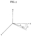
- an ultrasonic three-dimensional image formation apparatus using a cross array includes a cross array 10 constituted by two linear phased arrays 11 and 12 perpendicular to each other.
- Each of the transmission linear phased array 11 and the reception linear phased array 12 has an inter element spacing of ⁇ /2 in which ⁇ is the ultrasound wavelength and includes L square transducer elements the length whose one side is slightly smaller than ⁇ /2.
- the two linear phased arrays 11 and 12 share one transducer element positioned in an origin on the X-Y coordinate axes as a respective center array element.
- the transmission linear phased array 11 is used for transmission of ultrasonic waves, and arranged in the X-axis direction in Fig. 2.
- the receiving linear phased array 12 is used for reception of ultrasonic echoes, and arranged in the Y-axis direction in Fig. 2.
- the number of transducer elements constituting each linear phased array 11 or 12 is preferably 64 or 128.
- the square shown in the X-axis and the Y-axis of Fig. 2 are transducer elements constituting the transmission linear phased array 11 and the reception linear phased array 12.
- a transmitter 20 supplies an electrical signal for generation of ultrasonic waves to the transmission linear phased array 11.
- the ultrasonic waves transmitted by the transmission linear phased array 11 in the focusing form on a focal point are reflected by obstacles while travelling in the human body.
- the ultrasonic echoes returning to a cross array 10 are converted into electrical signals by the transducer elements in the reception linear phased array 12.
- a receiver 30 receives the electrical signals output from the reception linear phased array 12 and converts the received analog electrical signal into digital form after performing various signal processing procedures which are performed in a typical ultrasonic image formation apparatus with respect to the received analog electrical signals.
- a parallel beam former 40 performs a parallel beam forming with respect to the digital signals suppled from the receiver 30.
- An image signal processor 50 receives all scan line signals generated in the parallel beam former 40 and performs various image and picture processing procedures with respect to the received signals in order to generate an image signal in various forms to be displayed on a display 60.
- a controller 70 controls the operations of the above-described blocks to obtain a three-dimensional image in desired form.
- each transducer element of the transmission linear phased array 11 When the transmitter 20 supplies the electrical signals to the transmission linear phased array 11 under control of the controller 70, each transducer element of the transmission linear phased array 11 generates ultrasonic waves.
- the width of the transmission beam plane in the azimuth direction is determined by the size of the transducer element constituting the transmission linear phased array 11.
- only limiting area in the transmission beam plane becomes an effective area for three-dimensional image formation.
- an effective transmission beam plane can be formed in a wider area or all desired areas.
- the transmitter 20 is modified according to the used technique.
- the ultrasonic echoes reflect when the transmitted ultrasonic signal travels the inside of the human body are converted into electrical signals by the transducer elements of the reception linear phased array 12.
- the receiver 30 performs pre-amplification, time gain compensation, and filtering with respect to the ultrasonic signals converted by each reception transducer elements.
- Analog-to-digital (A/D) converters (not shown) which is provided in the receiver 30 convert the ultrasonic signals in digital form.
- the parallel beam former 40 receives the digital ultrasonic signals output from the receiver 30 and performs a parallel beam forming with respect to the received digital signals.
- a reception beam plane is formed and shown in parallel with the X-axis in Fig. 2.
- a final pattern of the ultrasonic beam considering transmission and reception becomes a product of a transmission beam pattern and a reception beam pattern.
- the parallel beam former 40 performs apodization during parallel beam forming in order to reduce a side lobe level.
- the beam width on the scan line obtained as described above is defined as follows: 1) The width of the elevation direction is same as that of the beam width of the transmission beam width. 2) The beam width and the resolution of the azimuth direction are the same as those of the reception beam plane, that is, the beam pattern of the azimuth direction is a one-way beam pattern of only the reception linear phased array 12.
- the resolution of the azimuth direction of the Fig. 2 apparatus can be controlled by controling the transmitter 20, in such a manner that the resolution of the Fig. 2 apparatus is more excellent than that of the exisiting two-dimensional image formation apparatus.
- the linear phased arrays 11 and 12 constituting the cross array 10 are used for transmission and reception, respectively and a parallel beam forming is performed at the time of reception, in order to perform a scan for one plane of image with a one-time transmission. That is, the Fig. 2 apparatus can scan one plane of a three-dimensional image when an existing two-dimensional image formation apparatus obtains a one scan line.
- the image signal processor 50 performs various signal processing procedures for obtaining an excellent quality of image with respect to the signal focused on all the scan lines acquired in the parallel beam former 40, and performs and image processing and a picture signal processing for generating all types of two-dimensional images and three-dimensional images to be displayed on the display 60 using the thus formed three-dimensional image data.
- the controller 70 performs control of all the operations and processing procedures, generation of the transmission pulses and transmission beam forming, the receiver, the parallel beam former, repeat control of the transmission and reception beam forming, and control of the image and signal processing.
- the number of both or each of the transmission and reception arrays, complexity of the transmitter 20 and the receiver 30 therefor are similar to those of the existing two-dimensional image formation apparatus.
- the complexity of the parallel beam former 40 for parallel focusing all the scan lines constituting one section simultaneously can be several tens times that of the beam former in the existing two-dimensional image formation apparatus in view of size of the circuit and cost thereof.
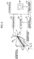
- the present invention provides a more economic and realistic three-dimensional image formation apparatus using an three-dimensional image formation method which uses a cross array of the present invention in the structure of a general two-dimensional image formation apparatus as shown in Fig. 3.
- the three-dimensional image formation apparatus of Fig. 3 adds a cross array, a data storage portion 180 and a three-dimensional image signal processor 190 in the existing two-dimensional image formation apparatus.
- the data storage portion 180 can be constituted by a number of semiconductor chips or a high-speed, large capacity hard disk.
- the three dimensional image signal processor 190 can be constituted by a high-speed digital signal processor (DSP) or a large capacity, high speed ASIC for specific calculation or routines.
- DSP digital signal processor
- a transmitter 120, a receiver 130, a reception beam former 140 and a two dimensional image signal processor 150 are the same as those of a general two-dimensional image apparatus.
- a transmission linear phased array 111 and a reception linear phased array 112 each of which comprised of 64 or 128 transducer elements are connected to the transmitter 120 and the receiver 130, respectively.
- the output of the receiver 130 is input to the reception beam former 140 and the data storage portion 180, simultaneously.
- the transmitter 120 enables the transmission linear phased array 111 to operate so that a transmission beam plane is formed at an elevation angle of 0° in each transmission.
- the ultrasonic echo signals received in the reception linear phased array 112 are processed in the receiver 130, and then focused on a single scan line corresponding to one azimuth angle by the reception beam former 140.
- the focused signal is processed by the two-dimensional image signal processor 150 and displayed on the display 160.
- the three-dimensional image mode using the Fig. 3 apparatus is performed in the following sequence: 1) A three-dimensional area to be scanned is determined using the two-dimensional image mode as described above. 2) A cross array 100 is positioned in the center of the determined three dimensional area. 3) A transmission and reception procedure for three-dimensional scan described with reference to the Fig. 2 apparatus is performed, by depressing a specific button (not shown) for setting a three dimensional image mode after completing the step 2). 4) The outputs of the receiver 130 corresponding to all the transducer elements of the reception linear phased array in each transmission in step 3) are stored in the data storage portion 180.
- the three-dimensional image signal processor 190 reads the data stored in the data storage portion 180, performs a beam focusing with respect to all scan lines in the three-dimensional scan area, and performs a required three-dimensional image processing, to thereby supply two-dimensional or three-dimensional image information to be displayed to the display 170.
- the three-dimensional image formation method using the Fig. 3 apparatus as described above performs a scan operation (for transmission and reception) of a three-dimensional image formation on a real time basis, and performs reception beam focusing, three-dimensional image processing and restoring on a non-real time basis, while the Fig. 2 apparatus obtains the three-dimensional image on a real time basis.
- the three-dimensional image formation procedures can be done as in the Fig. 2 apparatus on a real time basis
- the three-dimensional image searching for obtaining clinical information can be done on a non-real time basis. Accordingly, the above-described method with reference to the Fig. 3 apparatus is also valid. Thus, a huge parallel beam former is not necessary as in the Fig. 2 apparatus.
- the three-dimensional image signal processor 190 can be replaced by an externally linked computer.
- the data storage portion 180 has a high-speed external computer interface.
- the data storage portion 180 can be positioned in the external computer not in the three-dimensional image formation apparatus of Fig. 3.
- the Fig. 3 three-dimensional image formation apparatus can be simply constructed in comparison with the Fig. 2 image formation apparatus.
- the ultrasonic three-dimensional image formation apparatus of Fig. 3 can perform a real time four-dimensional scan when a memory capacity of the data storage portion 180 is sufficient. That is, the three-dimensional image information according to time can be obtained on a real time basis and then the change of the three-dimensional image can be checked according to time by performing reception beam focusing and image processing on a non-real time basis.
Landscapes
- Engineering & Computer Science (AREA)
- Health & Medical Sciences (AREA)
- Life Sciences & Earth Sciences (AREA)
- Physics & Mathematics (AREA)
- Remote Sensing (AREA)
- Radar, Positioning & Navigation (AREA)
- Acoustics & Sound (AREA)
- Radiology & Medical Imaging (AREA)
- Veterinary Medicine (AREA)
- Heart & Thoracic Surgery (AREA)
- Medical Informatics (AREA)
- Molecular Biology (AREA)
- Surgery (AREA)
- Animal Behavior & Ethology (AREA)
- General Health & Medical Sciences (AREA)
- Public Health (AREA)
- Biomedical Technology (AREA)
- Pathology (AREA)
- Nuclear Medicine, Radiotherapy & Molecular Imaging (AREA)
- Biophysics (AREA)
- Computer Networks & Wireless Communication (AREA)
- General Physics & Mathematics (AREA)
- Ultra Sonic Daignosis Equipment (AREA)
- Measurement Of Velocity Or Position Using Acoustic Or Ultrasonic Waves (AREA)
- Image Processing (AREA)
- Image Analysis (AREA)
- Investigating Or Analyzing Materials By The Use Of Ultrasonic Waves (AREA)
Applications Claiming Priority (2)
| Application Number | Priority Date | Filing Date | Title |
|---|---|---|---|
| KR1019960043565A KR100274653B1 (ko) | 1996-10-01 | 1996-10-01 | 교차 어레이를 이용한 초음파 3차원영상화 방법 및 장치 |
| KR9643565 | 1996-10-01 |
Publications (3)
| Publication Number | Publication Date |
|---|---|
| EP0834750A2 true EP0834750A2 (de) | 1998-04-08 |
| EP0834750A3 EP0834750A3 (de) | 1998-10-28 |
| EP0834750B1 EP0834750B1 (de) | 2004-04-21 |
Family
ID=19476011
Family Applications (1)
| Application Number | Title | Priority Date | Filing Date |
|---|---|---|---|
| EP97116927A Expired - Lifetime EP0834750B1 (de) | 1996-10-01 | 1997-09-30 | Verfahren und Vorrichtung zum dreidimensionalen Ultraschall-Abbilden mittels gekreuzter Gruppenantenne |
Country Status (5)
| Country | Link |
|---|---|
| US (1) | US5901708A (de) |
| EP (1) | EP0834750B1 (de) |
| JP (1) | JPH1170110A (de) |
| KR (1) | KR100274653B1 (de) |
| DE (1) | DE69728728T2 (de) |
Cited By (1)
| Publication number | Priority date | Publication date | Assignee | Title |
|---|---|---|---|---|
| GB2474103A (en) * | 2009-09-15 | 2011-04-06 | Oceanscan Ltd | Scanning apparatus and method |
Families Citing this family (23)
| Publication number | Priority date | Publication date | Assignee | Title |
|---|---|---|---|---|
| US6234968B1 (en) * | 1999-06-15 | 2001-05-22 | Acuson Corporation | 3-D diagnostic medical ultrasound imaging using a 1-D array |
| US6704589B1 (en) * | 1999-07-30 | 2004-03-09 | Siemens Aktiengesellschaft | Method and device for recording an image of an object surface using focussed radiation |
| US6524244B1 (en) * | 1999-09-14 | 2003-02-25 | Ecton Inc. | Medical diagnostic ultrasound system and method |
| US6368276B1 (en) * | 1999-11-23 | 2002-04-09 | James K. Bullis | Deep penetration beamformed television |
| US6352510B1 (en) | 2000-06-22 | 2002-03-05 | Leonid S. Barabash | Ultrasound transducers for real time two and three dimensional image acquisition |
| US6537220B1 (en) * | 2001-08-31 | 2003-03-25 | Siemens Medical Solutions Usa, Inc. | Ultrasound imaging with acquisition of imaging data in perpendicular scan planes |
| US20030149364A1 (en) * | 2002-02-01 | 2003-08-07 | Ajay Kapur | Methods, system and apparatus for digital imaging |
| JP4201311B2 (ja) * | 2002-03-12 | 2008-12-24 | 株式会社日立メディコ | 超音波診断装置 |
| CN1893878A (zh) * | 2003-12-16 | 2007-01-10 | 株式会社日立医药 | 超声波体动检测装置、和使用该装置的图像提示装置及超声波治疗装置 |
| US7963919B2 (en) * | 2005-12-07 | 2011-06-21 | Siemens Medical Solutions Usa, Inc. | Ultrasound imaging transducer array for synthetic aperture |
| US8465431B2 (en) * | 2005-12-07 | 2013-06-18 | Siemens Medical Solutions Usa, Inc. | Multi-dimensional CMUT array with integrated beamformation |
| CN101373181B (zh) * | 2007-08-24 | 2012-03-21 | 深圳迈瑞生物医疗电子股份有限公司 | 实时计算逐点变迹系数的方法及装置 |
| KR101053286B1 (ko) * | 2009-07-03 | 2011-08-01 | 삼성전기주식회사 | 초음파 프로브 및 초음파 진단장치 |
| KR101378085B1 (ko) | 2012-06-13 | 2014-03-27 | 삼성전자주식회사 | 2차원 배열 트랜스듀서 어레이를 이용한 3차원 초음파 볼륨 스캔 방법 및 장치 |
| GB2511556A (en) * | 2013-03-07 | 2014-09-10 | Sharp Kk | Ultrasound imaging |
| DE102013004924B4 (de) * | 2013-03-22 | 2018-05-03 | GE Sensing & lnspection Technologies GmbH | Bildgebungssystem und -verfahren |
| CN106461765B (zh) * | 2014-06-13 | 2019-12-31 | B-K医疗公司 | 三维(3d)和/或四维(4d)超声成像 |
| JP2017046811A (ja) * | 2015-08-31 | 2017-03-09 | セイコーエプソン株式会社 | 超音波デバイス、超音波モジュール、及び超音波測定機 |
| CN105974421A (zh) * | 2016-06-22 | 2016-09-28 | 杨越 | 利用正交阵列形成无人船监控区域超声波三维图像的方法 |
| CN108267745A (zh) * | 2016-06-22 | 2018-07-10 | 安溪县景宏技术咨询有限公司 | 图像形成装置及其图像形成方法 |
| JP2023114623A (ja) * | 2022-02-07 | 2023-08-18 | キヤノンメディカルシステムズ株式会社 | 超音波診断装置 |
| US12254540B2 (en) * | 2022-08-31 | 2025-03-18 | Sonaria 3D Music, Inc. | Frequency interval visualization education and entertainment system and method |
| CN121208150B (zh) * | 2025-11-26 | 2026-04-24 | 之江实验室 | 超声二维相控阵探头及三维成像方法 |
Family Cites Families (8)
| Publication number | Priority date | Publication date | Assignee | Title |
|---|---|---|---|---|
| US3964014A (en) * | 1974-10-15 | 1976-06-15 | General Electric Company | Sonic transducer array |
| US4694434A (en) * | 1984-06-12 | 1987-09-15 | Von Ramm Olaf T | Three-dimensional imaging system |
| JPH02268747A (ja) * | 1989-04-11 | 1990-11-02 | Toshiba Corp | 超音波診断装置 |
| US5704361A (en) * | 1991-11-08 | 1998-01-06 | Mayo Foundation For Medical Education And Research | Volumetric image ultrasound transducer underfluid catheter system |
| US5379769A (en) * | 1992-11-30 | 1995-01-10 | Hitachi Medical Corporation | Ultrasonic diagnostic apparatus for displaying an image in a three-dimensional image and in a real time image and a display method thereof |
| US5323362A (en) * | 1993-06-07 | 1994-06-21 | Westinghouse Electric Corporation | Sonar system employing synthetic orthogonal array |
| US5503152A (en) * | 1994-09-28 | 1996-04-02 | Tetrad Corporation | Ultrasonic transducer assembly and method for three-dimensional imaging |
| US5797845A (en) * | 1996-11-04 | 1998-08-25 | Barabash; Leonid S. | Ultrasound apparatus for three dimensional image reconstruction |
-
1996
- 1996-10-01 KR KR1019960043565A patent/KR100274653B1/ko not_active Expired - Lifetime
-
1997
- 1997-09-30 DE DE69728728T patent/DE69728728T2/de not_active Expired - Lifetime
- 1997-09-30 EP EP97116927A patent/EP0834750B1/de not_active Expired - Lifetime
- 1997-10-01 US US08/942,348 patent/US5901708A/en not_active Expired - Lifetime
- 1997-10-01 JP JP9268929A patent/JPH1170110A/ja active Pending
Cited By (2)
| Publication number | Priority date | Publication date | Assignee | Title |
|---|---|---|---|---|
| GB2474103A (en) * | 2009-09-15 | 2011-04-06 | Oceanscan Ltd | Scanning apparatus and method |
| GB2474103B (en) * | 2009-09-15 | 2012-05-23 | Oceanscan Ltd | Scanning apparatus and method |
Also Published As
| Publication number | Publication date |
|---|---|
| DE69728728D1 (de) | 2004-05-27 |
| KR19980025479A (ko) | 1998-07-15 |
| JPH1170110A (ja) | 1999-03-16 |
| DE69728728T2 (de) | 2007-04-05 |
| EP0834750B1 (de) | 2004-04-21 |
| EP0834750A3 (de) | 1998-10-28 |
| US5901708A (en) | 1999-05-11 |
| KR100274653B1 (ko) | 2000-12-15 |
Similar Documents
| Publication | Publication Date | Title |
|---|---|---|
| EP0834750B1 (de) | Verfahren und Vorrichtung zum dreidimensionalen Ultraschall-Abbilden mittels gekreuzter Gruppenantenne | |
| JP3218216B2 (ja) | 三次元画像処理装置 | |
| JP5174010B2 (ja) | 統合ビーム化が行われる方法および変換器アレイ | |
| US5235986A (en) | Variable origin-variable angle acoustic scanning method and apparatus for a curved linear array | |
| US4159462A (en) | Ultrasonic multi-sector scanner | |
| US5820564A (en) | Method and apparatus for surface ultrasound imaging | |
| US7135809B2 (en) | Ultrasound transducer | |
| US6923066B2 (en) | Ultrasonic transmitting and receiving apparatus | |
| EP0642036A2 (de) | Ultraschall-Diagnosegerät | |
| EP1235080A2 (de) | Verfahren und Vorrichtung zur Ultraschallabbildung | |
| JP3290092B2 (ja) | 超音波診断装置 | |
| JP2003000599A (ja) | リアルタイム3次元超音波映像装置および探触子 | |
| EP0293803A2 (de) | Ultraschallgerät mit fächerförmiger Abtastung für die Fehlererkennung | |
| JP2000325344A (ja) | 超音波診断装置 | |
| JP2008062050A (ja) | スキャンラインを制御する超音波システム及び方法 | |
| US6640633B2 (en) | Ultrasonic imaging method and ultrasonic imaging apparatus | |
| JP2005118081A (ja) | 超音波診断装置 | |
| US4484476A (en) | Acoustic microscope device | |
| JPH07236642A (ja) | 超音波診断装置 | |
| JP3256698B2 (ja) | 超音波診断装置 | |
| JPH02147052A (ja) | 電子走査型超音波診断装置 | |
| JP3101301B2 (ja) | 超音波診断装置 | |
| JPH0614926A (ja) | 超音波診断装置 | |
| JP4154043B2 (ja) | 超音波撮像装置 | |
| JPH114824A (ja) | 最小値投影像形成方法および超音波撮像装置 |
Legal Events
| Date | Code | Title | Description |
|---|---|---|---|
| PUAI | Public reference made under article 153(3) epc to a published international application that has entered the european phase |
Free format text: ORIGINAL CODE: 0009012 |
|
| AK | Designated contracting states |
Kind code of ref document: A2 Designated state(s): DE FR GB IT NL |
|
| RIN1 | Information on inventor provided before grant (corrected) |
Inventor name: SONG, TAI-KYUNG, ELECT. ENG. DEPT. Inventor name: CHANG, SEONG-HO |
|
| PUAL | Search report despatched |
Free format text: ORIGINAL CODE: 0009013 |
|
| AK | Designated contracting states |
Kind code of ref document: A3 Designated state(s): AT BE CH DE DK ES FI FR GB GR IE IT LI LU MC NL PT SE |
|
| 17P | Request for examination filed |
Effective date: 19990324 |
|
| AKX | Designation fees paid |
Free format text: DE FR GB IT NL |
|
| 17Q | First examination report despatched |
Effective date: 20020301 |
|
| GRAP | Despatch of communication of intention to grant a patent |
Free format text: ORIGINAL CODE: EPIDOSNIGR1 |
|
| GRAS | Grant fee paid |
Free format text: ORIGINAL CODE: EPIDOSNIGR3 |
|
| GRAA | (expected) grant |
Free format text: ORIGINAL CODE: 0009210 |
|
| AK | Designated contracting states |
Kind code of ref document: B1 Designated state(s): DE FR GB IT NL |
|
| PG25 | Lapsed in a contracting state [announced via postgrant information from national office to epo] |
Ref country code: NL Free format text: LAPSE BECAUSE OF FAILURE TO SUBMIT A TRANSLATION OF THE DESCRIPTION OR TO PAY THE FEE WITHIN THE PRESCRIBED TIME-LIMIT Effective date: 20040421 |
|
| REG | Reference to a national code |
Ref country code: GB Ref legal event code: FG4D |
|
| REF | Corresponds to: |
Ref document number: 69728728 Country of ref document: DE Date of ref document: 20040527 Kind code of ref document: P |
|
| PG25 | Lapsed in a contracting state [announced via postgrant information from national office to epo] |
Ref country code: DE Free format text: LAPSE BECAUSE OF FAILURE TO SUBMIT A TRANSLATION OF THE DESCRIPTION OR TO PAY THE FEE WITHIN THE PRESCRIBED TIME-LIMIT Effective date: 20040722 |
|
| PG25 | Lapsed in a contracting state [announced via postgrant information from national office to epo] |
Ref country code: GB Free format text: LAPSE BECAUSE OF NON-PAYMENT OF DUE FEES Effective date: 20040930 |
|
| NLV1 | Nl: lapsed or annulled due to failure to fulfill the requirements of art. 29p and 29m of the patents act | ||
| REG | Reference to a national code |
Ref country code: FR Ref legal event code: RN |
|
| PLBE | No opposition filed within time limit |
Free format text: ORIGINAL CODE: 0009261 |
|
| STAA | Information on the status of an ep patent application or granted ep patent |
Free format text: STATUS: NO OPPOSITION FILED WITHIN TIME LIMIT |
|
| EN | Fr: translation not filed | ||
| 26N | No opposition filed |
Effective date: 20050124 |
|
| REG | Reference to a national code |
Ref country code: FR Ref legal event code: FC |
|
| GBPC | Gb: european patent ceased through non-payment of renewal fee |
Effective date: 20040930 |
|
| ET | Fr: translation filed | ||
| REG | Reference to a national code |
Ref country code: FR Ref legal event code: ST Effective date: 20111223 |
|
| PG25 | Lapsed in a contracting state [announced via postgrant information from national office to epo] |
Ref country code: FR Free format text: LAPSE BECAUSE OF NON-PAYMENT OF DUE FEES Effective date: 20040930 |
|
| REG | Reference to a national code |
Ref country code: FR Ref legal event code: D3 Effective date: 20120509 |
|
| PGRI | Patent reinstated in contracting state [announced from national office to epo] |
Ref country code: FR Effective date: 20120101 |
|
| REG | Reference to a national code |
Ref country code: FR Ref legal event code: PLFP Year of fee payment: 20 |
|
| PGFP | Annual fee paid to national office [announced via postgrant information from national office to epo] |
Ref country code: IT Payment date: 20160909 Year of fee payment: 20 Ref country code: DE Payment date: 20160805 Year of fee payment: 20 |
|
| PGFP | Annual fee paid to national office [announced via postgrant information from national office to epo] |
Ref country code: FR Payment date: 20160809 Year of fee payment: 20 |
|
| REG | Reference to a national code |
Ref country code: DE Ref legal event code: R071 Ref document number: 69728728 Country of ref document: DE |