EP0834794A1 - Schaltschrank mit einem Schaltfach zur Unterbringung einer ausziehbaren Arbeitsplatte - Google Patents
Schaltschrank mit einem Schaltfach zur Unterbringung einer ausziehbaren Arbeitsplatte Download PDFInfo
- Publication number
- EP0834794A1 EP0834794A1 EP97402288A EP97402288A EP0834794A1 EP 0834794 A1 EP0834794 A1 EP 0834794A1 EP 97402288 A EP97402288 A EP 97402288A EP 97402288 A EP97402288 A EP 97402288A EP 0834794 A1 EP0834794 A1 EP 0834794A1
- Authority
- EP
- European Patent Office
- Prior art keywords
- shelf
- rack
- electrical cabinet
- cabinet according
- tablet
- Prior art date
- Legal status (The legal status is an assumption and is not a legal conclusion. Google has not performed a legal analysis and makes no representation as to the accuracy of the status listed.)
- Granted
Links
- 239000004020 conductor Substances 0.000 claims description 4
- 238000003780 insertion Methods 0.000 claims description 2
- 230000037431 insertion Effects 0.000 claims description 2
- 210000000056 organ Anatomy 0.000 claims 1
- 238000000605 extraction Methods 0.000 description 3
- 230000000903 blocking effect Effects 0.000 description 2
- 230000006835 compression Effects 0.000 description 2
- 238000007906 compression Methods 0.000 description 2
- 230000004308 accommodation Effects 0.000 description 1
- 210000000245 forearm Anatomy 0.000 description 1
- 238000000034 method Methods 0.000 description 1
- 230000002093 peripheral effect Effects 0.000 description 1
- 230000000284 resting effect Effects 0.000 description 1
- 230000000717 retained effect Effects 0.000 description 1
Images


Classifications
-
- A—HUMAN NECESSITIES
- A47—FURNITURE; DOMESTIC ARTICLES OR APPLIANCES; COFFEE MILLS; SPICE MILLS; SUCTION CLEANERS IN GENERAL
- A47B—TABLES; DESKS; OFFICE FURNITURE; CABINETS; DRAWERS; GENERAL DETAILS OF FURNITURE
- A47B21/00—Tables or desks for office equipment, e.g. typewriters, keyboards
- A47B21/03—Tables or desks for office equipment, e.g. typewriters, keyboards with substantially horizontally extensible or adjustable parts other than drawers, e.g. leaves
- A47B21/0314—Platforms for supporting office equipment
-
- A—HUMAN NECESSITIES
- A47—FURNITURE; DOMESTIC ARTICLES OR APPLIANCES; COFFEE MILLS; SPICE MILLS; SUCTION CLEANERS IN GENERAL
- A47B—TABLES; DESKS; OFFICE FURNITURE; CABINETS; DRAWERS; GENERAL DETAILS OF FURNITURE
- A47B88/00—Drawers for tables, cabinets or like furniture; Guides for drawers
- A47B88/40—Sliding drawers; Slides or guides therefor
- A47B88/453—Actuated drawers
- A47B88/46—Actuated drawers operated by mechanically-stored energy, e.g. by springs
- A47B88/463—Actuated drawers operated by mechanically-stored energy, e.g. by springs self-opening
-
- A—HUMAN NECESSITIES
- A47—FURNITURE; DOMESTIC ARTICLES OR APPLIANCES; COFFEE MILLS; SPICE MILLS; SUCTION CLEANERS IN GENERAL
- A47B—TABLES; DESKS; OFFICE FURNITURE; CABINETS; DRAWERS; GENERAL DETAILS OF FURNITURE
- A47B88/00—Drawers for tables, cabinets or like furniture; Guides for drawers
- A47B88/40—Sliding drawers; Slides or guides therefor
- A47B88/453—Actuated drawers
- A47B88/46—Actuated drawers operated by mechanically-stored energy, e.g. by springs
- A47B88/467—Actuated drawers operated by mechanically-stored energy, e.g. by springs self-closing
-
- H—ELECTRICITY
- H02—GENERATION; CONVERSION OR DISTRIBUTION OF ELECTRIC POWER
- H02B—BOARDS, SUBSTATIONS OR SWITCHING ARRANGEMENTS FOR THE SUPPLY OR DISTRIBUTION OF ELECTRIC POWER
- H02B1/00—Frameworks, boards, panels, desks, casings; Details of substations or switching arrangements
- H02B1/26—Casings; Parts thereof or accessories therefor
- H02B1/30—Cabinet-type casings; Parts thereof or accessories therefor
- H02B1/306—Accessories, e.g. windows
-
- H—ELECTRICITY
- H02—GENERATION; CONVERSION OR DISTRIBUTION OF ELECTRIC POWER
- H02B—BOARDS, SUBSTATIONS OR SWITCHING ARRANGEMENTS FOR THE SUPPLY OR DISTRIBUTION OF ELECTRIC POWER
- H02B1/00—Frameworks, boards, panels, desks, casings; Details of substations or switching arrangements
- H02B1/26—Casings; Parts thereof or accessories therefor
- H02B1/30—Cabinet-type casings; Parts thereof or accessories therefor
- H02B1/32—Mounting of devices therein
- H02B1/34—Racks
- H02B1/36—Racks with withdrawable units
-
- A—HUMAN NECESSITIES
- A47—FURNITURE; DOMESTIC ARTICLES OR APPLIANCES; COFFEE MILLS; SPICE MILLS; SUCTION CLEANERS IN GENERAL
- A47B—TABLES; DESKS; OFFICE FURNITURE; CABINETS; DRAWERS; GENERAL DETAILS OF FURNITURE
- A47B2200/00—General construction of tables or desks
- A47B2200/008—Tables or desks having means for applying electronic or electric devices
- A47B2200/0083—Cable or current inlet for drawer or shelf
Definitions
- the present invention relates to an electrical distribution cabinet, or to a similar device, incorporating in its facade a locker which can accommodate a extractable shelf to support a control keyboard or others interface members for an operator.
- the locker of such a cabinet includes a horizontal bottom, vertical side walls and an open front face which can be sealed by a door, the shelf being extractable in translation towards the front of the locker and guided by telescopic slides mounted in the locker.
- the tablet is extractable in translation by traction on its front face after opening the locker door.
- the shelf is sometimes attached to the door, as illustrated in the FR 2658368, and then pulls directly on the door to extract it.
- This mode has the advantage of allowing quick access to the tablet, from opening the door.
- the locker must be specifically adapted to the housing of an extractable shelf, otherwise, being without a door, it cannot be used to another use.
- the invention therefore aims to facilitate the extraction of the tablet in a quick and simple way while allowing to use a standard locker to his accommodation.
- the cabinet is characterized in that the shelf is extractable thanks to an elastic ejection system mounted in the locker, and means for locking the shelf in the retracted position in the rack are provided in the locker.
- the elastic ejection system comprises a folded arm comprising a rear part and a front part hinged together, and a elastic device associated with the rear part and / or the front part of the arm for cause its deployment.
- the elastic device preferably consists of a gas spring.
- the elastic ejection system and the locking means constitute advantageously means for ejecting and storing the tablet of the type push-push.
- the locking means comprise an elastic latch and a stop, mounted in the locker and bitter on the shelf, the latch and the stop cooperating by snap-fastening and disengaging following two thrusts exerted in the direction of insertion of the tablet for locking and unlocking the tablet respectively.
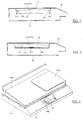
- FIG. 1 illustrates a rack 10 intended to be incorporated in the front face an electrical cabinet not shown.
- Locker 10 is fixed between uprights vertical and cross members of a frame forming the chassis of the electrical cabinet.
- the rack 10 includes an open vertical front face 11, a wall vertical bitter 12, a horizontal bottom 13, vertical side walls 14 and a horizontal upper part or cover 15, the front face 11 being able to be closed tightly by a folding door 30, visible in FIG. 2.
- the rack 10 is intended to accommodate a shelf 40 serving to support a keyboard 40a or other interface elements with an operator.
- the shelf 40 can be extracted from the front face 11 of the rack in position door 30 open. Its extraction is carried out by an ejection system 50 elastic, mounted in the locker 10, and its guide is established by slides telescopic 80 inside locker 10. Telescopic slides 80 include each a fixed part 81 mounted in the rack 10 and a sliding part 82 fixed to the shelf 40.
- the tablet 40 includes a horizontal upper face 41 serving to keyboard support 40a, lateral faces 44 and a vertical rear face 42, the upper part 43 protrudes from the plane containing the face 41 to serve back stop at keyboard 40a.
- each slide 80 is advantageously fixed on the inner face of a lateral face 44 (not illustrated in the figures) so to make it invisible in the extracted position of the tablet.
- the fixed part 81 of each slide is arranged parallel to a side wall 14 of the rack and is fixed to a square 16 or other similar element integral with the rack 10 so as to leave between the square 16 and the internal face 14a of the side wall 14 a space suitable for housing a side wall 44 of the shelf.
- the bitter side 42 of the tablet is adapted when the brackets 16 and the rails 80 pass. This method of attachment allows, by compared to that of the state of the art, to use a tablet 40 of greater width.
- the lateral faces 44 of the tablet each have a slot longitudinal 46 of suitable shape for the passage of a zipper 47.
- the zipper 47 forms a receiving surface for a carpet 48 for the mobility of a mouse 49.
- the pull tab 47 is flat and extends in a plane QQ '. It presents two lateral ends 47a and 47b which project from the plane QQ '.
- the pull tab 47 is movable transversely to the left or to the right and its extraction stroke is stopped by stop or blocking means associated with the tablet 40.
- the shelf 40 has slides transverse 41a for the mobility of the pull tab 47, and one or two internal stops 41b central units intended, to stop the pull tab, to cooperate with one of the ends lateral 47a or 47b opposite to that by which the zipper is extracted.
- the pull tab 47 can be pulled out using a slide telescopic transverse 41c, the fixed part and the mobile part of which are mounted respectively, internally to the shelf 40, on brackets 40b for example, and under the lower outer face 47c of the pull tab 47.
- the slide 41c is suitable for slide in both directions and has a locking means in the middle of the race in order to stop the pull tab in the extended position.
- the support of reception for the mobility of the mouse 49 is not a zipper but a tablet removable 47d clipable on either side of the shelf 40 and can be folded for its housing above the keyboard 40a to allow the storage of the shelf 40 in the locker.
- the upper face 41 of the tablet has a front part ergonomic 45 tilted forward and down and on which the forearms of the operator are intended to rest.
- the inclined part 45 comprises means hooking the mouse 49 for its storage. These means can for example consist of a strap. According to a variant, it is possible to provide in this inclined part 45 a housing 45a with a horizontal bottom on which the mouse 49 can rest (Figure 5).
- the elastic ejection system 50 consists of a folded arm 60 and a elastic device 70 allowing the arm 60 to relax.
- the folded arm 60 comprises a rear part 61 whose free end 62 is fixed to the locker 10 and a front part 63 whose free end 64 is connected to the shelf 40.
- the end 62 is assembled to the inner face 14a of a side wall 14 of the rack 10 and the end 64 is fixed to the rear face 42 of the shelf 40.
- the elastic device 70 performs the ejection function of the arm 60 and by consequent of the tablet 40. It is positioned in the plane containing the arm 60 and is fixed between the internal faces 61a and 63a of the rear parts 61 and respectively before 63 of the arm 60. In the folded position, the arm 60 is subjected to the tension of the device elastic 70 in compression; when the arm 60 is free to unfold, the device 70 can relax and consequently eject the front part 63 of the arm.
- the elastic device 70 is understood by any compression means elastic, such as a torsion spring for example. In one embodiment preferred, it consists of a gas spring.
- Locking means 72 allow the tablet to be locked in retracted position, that is to say in the folded position of the arm 60, or the unlocking of the tablet in the unfolded position of the arm 60.
- the locking means 72 comprise a resilient latch 72a and a part stop 72b, the latch 72a being intended to cooperate by snap-fastening and release with stopper part 72b for locking and unlocking of the tablet.
- the latch 72a is fixed to a bracket 73 resting on the bottom 13 of the locker and is arranged below the arm 60.
- the stop piece 72b is mounted on the rear face 42 of the tablet.
- the elastic catch 72a can be provided a locking cam and fixed to the rear part 42 of the shelf, and the part stop 72b can be constituted by the bracket 73 provided with a recess in which the cam is intended to engage and to turn a quarter of a turn by pushing on the latch 72a so as to lock it.
- the ejection system 50 in particular the elastic device 70, and the locking means 72 constitute means for ejecting and storing the push-push type tablet 40 which allows the ejection of the tablet and store it quickly.
- push-push type means causing the locking of the tablet following a push exerted on it to engage it in the locker, at the end of the race, and causing the unlocking of the tablet following a push in the same meaning.
- the thrust on its front face unlocks the latch 72a, then releasing releases the latch 72a from its stop 72b, and under the action of the spring 70, the arm 60 is deployed by ejecting the front part 63 which projects the shelf 40 towards the outside of the rack 10.
- the thrust on its front face allows it to enter the locker 10, the arm 60 is folding, the stop 72b meets the latch 72a which locks elastically in blocking the tablet.
- the upper part 43 of the tablet has a recess 43a.
- the arm 60 advantageously serves to support and positioning to these conductors in order to route them to the rear wall 12 of the locker; drivers can be retained by any means of support mounted on the arm 60, such as cable ties or notches. The guiding the conductors in the rack 10 thus avoiding jamming them in the device elastic 70, in the locking means 72 and / or in the slides 80.
- the front face 11 of the latter can be closed by the door 30 which can be folded down and illustrated in the Figure 2.
- the door 30 is independent of the shelf 40, it is fixed and hinged to uprights 20 of the cabinet by fixing and articulation devices 31 provided at its lower corners 30b.
- a device 31 includes a mounting part 32 fixed to the uprights 20, a bracket 33 secured to the inner face 30a of the door and a link 34 of connection between the part 32 and the bracket 33.
- the mounting part 32 comprises on the one hand an upper part 32a which has on its rear face a surface for fixing to uprights 20 and on its front face two parallel wings 32b, and on the other hand a part lower 32c which has an oblique slide 32d.
- the bracket 33 comprises at one free end a positioning lug 33a intended to slide in the slide 32d.
- the connecting rod 34 is fixed at one of its ends to the bracket 33 and is rotatably mounted at its opposite end between the wings 32b of the workpiece mounting 32.
- This device 31 known in the state of the art of hinged devices, allows the door 30 to be fully opened perpendicular to the uprights 20 without that it abuts in a lower panel 21 of the cabinet and in a lower cross member 22a of the cabinet separating the rack 10 from the bottom panel 21.
- a peripheral seal 35 is disposed on the inner face 30a of the door, it is intended to be applied on the uprights 20 and the upper crossbeams 22b and lower 22a of the cabinet so as to seal the locker.
- the folding door 30 is independent of the shelf 40 in order to use a standard locker. It goes without saying that the ejection system 50 elastic is also well suited to a tablet which integrally comprises its front face a door intended to close the front face 11 of the rack in the position re-entry of the tablet.
Landscapes
- Engineering & Computer Science (AREA)
- Power Engineering (AREA)
- Mechanical Engineering (AREA)
- Casings For Electric Apparatus (AREA)
- Warehouses Or Storage Devices (AREA)
- Drawers Of Furniture (AREA)
Applications Claiming Priority (2)
| Application Number | Priority Date | Filing Date | Title |
|---|---|---|---|
| FR9612285 | 1996-10-03 | ||
| FR9612285A FR2754417B1 (fr) | 1996-10-03 | 1996-10-03 | Armoire de distribution electrique munie d'un casier logeant une tablette extractible |
Publications (2)
| Publication Number | Publication Date |
|---|---|
| EP0834794A1 true EP0834794A1 (de) | 1998-04-08 |
| EP0834794B1 EP0834794B1 (de) | 2003-01-08 |
Family
ID=9496489
Family Applications (1)
| Application Number | Title | Priority Date | Filing Date |
|---|---|---|---|
| EP97402288A Expired - Lifetime EP0834794B1 (de) | 1996-10-03 | 1997-10-01 | Schaltschrank mit einem Schaltfach zur Unterbringung einer ausziehbaren Arbeitsplatte |
Country Status (4)
| Country | Link |
|---|---|
| EP (1) | EP0834794B1 (de) |
| DE (1) | DE69718264T2 (de) |
| ES (1) | ES2186856T3 (de) |
| FR (1) | FR2754417B1 (de) |
Cited By (3)
| Publication number | Priority date | Publication date | Assignee | Title |
|---|---|---|---|---|
| WO2008131962A1 (de) * | 2007-04-30 | 2008-11-06 | Grass Gmbh | Möbel und vorrichtung zum ausstossen eines möbelteils, das an einem feststehenden möbelteil bewegbar aufgenommen ist |
| CN114069444A (zh) * | 2021-11-25 | 2022-02-18 | 苏州市德惠机电设备有限公司 | 一种模块化组装式电气柜箱体及其装配工艺 |
| CN120497776A (zh) * | 2025-07-07 | 2025-08-15 | 宁德时代新能源科技股份有限公司 | 无功补偿装置 |
Citations (4)
| Publication number | Priority date | Publication date | Assignee | Title |
|---|---|---|---|---|
| US4931978A (en) * | 1988-10-21 | 1990-06-05 | Ring King Visibles | Computer support device with power control devices |
| FR2658368A1 (fr) * | 1990-02-13 | 1991-08-16 | Loh Rittal Werk Gmbh Co | Armoire de distribution a casier contenant une tirette avec volet rabattable. |
| DE4331110A1 (de) * | 1993-04-20 | 1994-10-27 | Loh Kg Rittal Werk | Schaltschrank mit einem Auszug |
| DE4330926A1 (de) * | 1993-09-13 | 1995-03-16 | Loh Kg Rittal Werk | Schaltschrank mit einem Schrankfach |
-
1996
- 1996-10-03 FR FR9612285A patent/FR2754417B1/fr not_active Expired - Lifetime
-
1997
- 1997-10-01 DE DE69718264T patent/DE69718264T2/de not_active Expired - Lifetime
- 1997-10-01 ES ES97402288T patent/ES2186856T3/es not_active Expired - Lifetime
- 1997-10-01 EP EP97402288A patent/EP0834794B1/de not_active Expired - Lifetime
Patent Citations (4)
| Publication number | Priority date | Publication date | Assignee | Title |
|---|---|---|---|---|
| US4931978A (en) * | 1988-10-21 | 1990-06-05 | Ring King Visibles | Computer support device with power control devices |
| FR2658368A1 (fr) * | 1990-02-13 | 1991-08-16 | Loh Rittal Werk Gmbh Co | Armoire de distribution a casier contenant une tirette avec volet rabattable. |
| DE4331110A1 (de) * | 1993-04-20 | 1994-10-27 | Loh Kg Rittal Werk | Schaltschrank mit einem Auszug |
| DE4330926A1 (de) * | 1993-09-13 | 1995-03-16 | Loh Kg Rittal Werk | Schaltschrank mit einem Schrankfach |
Cited By (3)
| Publication number | Priority date | Publication date | Assignee | Title |
|---|---|---|---|---|
| WO2008131962A1 (de) * | 2007-04-30 | 2008-11-06 | Grass Gmbh | Möbel und vorrichtung zum ausstossen eines möbelteils, das an einem feststehenden möbelteil bewegbar aufgenommen ist |
| CN114069444A (zh) * | 2021-11-25 | 2022-02-18 | 苏州市德惠机电设备有限公司 | 一种模块化组装式电气柜箱体及其装配工艺 |
| CN120497776A (zh) * | 2025-07-07 | 2025-08-15 | 宁德时代新能源科技股份有限公司 | 无功补偿装置 |
Also Published As
| Publication number | Publication date |
|---|---|
| FR2754417A1 (fr) | 1998-04-10 |
| FR2754417B1 (fr) | 1998-11-06 |
| EP0834794B1 (de) | 2003-01-08 |
| DE69718264D1 (de) | 2003-02-13 |
| DE69718264T2 (de) | 2003-08-28 |
| ES2186856T3 (es) | 2003-05-16 |
Similar Documents
| Publication | Publication Date | Title |
|---|---|---|
| EP1331712A1 (de) | Elektrisches Gerät zur Befestigung auf einer Hutprofiltragschiene | |
| FR2732499A3 (fr) | Coffret de montage d'unite de disque du type tiroir | |
| FR2755922A1 (fr) | Amenagement interieur pour vehicule tel que, par exemple, vehicule automobile | |
| EP1390597B1 (de) | Behälter für gegenstände | |
| EP0229556A1 (de) | Zugeordnete Elementgruppen, die die Umwandlung eines Kombifahrzeugs in ein Campingauto gestatten | |
| FR3007341A1 (fr) | Agencement d'une console possedant des elements depliables en table dans l'habitacle d'un vehicule | |
| FR2518626A1 (fr) | Mecanisme de verrouillage d'un panneau pivotant | |
| FR2690195A1 (fr) | Armoire dotée de portes pliables et coulissant de façon escamotable. | |
| EP0834794B1 (de) | Schaltschrank mit einem Schaltfach zur Unterbringung einer ausziehbaren Arbeitsplatte | |
| EP2760703B1 (de) | Vorrichtung zur befestigung eines kraftfahrzeugdachbalkens und anordnung für in verschiedenen konfigurationen montierte dachbalken mit einer solchen vorrichtung | |
| FR3002891A1 (fr) | Agencement d'une console possedant des elements convertibles en table dans l'habitacle d'un vehicule | |
| FR2984029A1 (fr) | Structure de support d'un appareil electrique de commande ou de protection electrique d'une cellule electrique moyenne tension | |
| FR2992264A1 (fr) | Dispositif de fermeture pour la mise en oeuvre d'un espace de rangement sous un siege de vehicule | |
| EP0651482B1 (de) | Trägervorrichtung für elektrische Geräte | |
| EP4428036A1 (de) | Flugzeugbordküchenmöbel mit einem wagenblockiersystem | |
| EP3710311B1 (de) | Innenraumanorndung zum tragen von lasten im oberen fahrzeuginnenraumteil | |
| FR2734954A1 (fr) | Pupitre pour le logement notamment d'appareillages electriques. | |
| EP0511918A1 (de) | Verriegelungseinrichtung einer Schublade; fester Betätigungshandgriff, Schublade und Schubladenschrank, die eine solche Einrichtung enthalten | |
| FR2775639A1 (fr) | Mecanisme d'articulation pour tablette rabattable, notamment pour vehicule automobile | |
| EP0724052A1 (de) | Türgriff eines Kraftfahrzeugs zur schnellen Montage durch ein Keil-Nockensystem | |
| FR3107295A1 (fr) | Dispositif de verrouillage pour une pièce mobile d’un véhicule | |
| EP4023830B1 (de) | Verriegelungssystem mit clip für bodenplatte | |
| WO2003105630A1 (fr) | Meuble pour le repassage | |
| EP0898916A1 (de) | Zentralverschluss für eine Briefkastenanlage | |
| FR3089168A1 (fr) | Console d’un véhicule avec support escamotable |
Legal Events
| Date | Code | Title | Description |
|---|---|---|---|
| PUAI | Public reference made under article 153(3) epc to a published international application that has entered the european phase |
Free format text: ORIGINAL CODE: 0009012 |
|
| AK | Designated contracting states |
Kind code of ref document: A1 Designated state(s): DE ES GB IT |
|
| 17P | Request for examination filed |
Effective date: 19980502 |
|
| AKX | Designation fees paid |
Free format text: DE ES GB IT |
|
| RBV | Designated contracting states (corrected) |
Designated state(s): DE ES GB IT |
|
| RAP1 | Party data changed (applicant data changed or rights of an application transferred) |
Owner name: SCHNEIDER ELECTRIC INDUSTRIES SA |
|
| RAP1 | Party data changed (applicant data changed or rights of an application transferred) |
Owner name: SCHNEIDER ELECTRIC INDUSTRIES SA |
|
| GRAG | Despatch of communication of intention to grant |
Free format text: ORIGINAL CODE: EPIDOS AGRA |
|
| GRAG | Despatch of communication of intention to grant |
Free format text: ORIGINAL CODE: EPIDOS AGRA |
|
| GRAH | Despatch of communication of intention to grant a patent |
Free format text: ORIGINAL CODE: EPIDOS IGRA |
|
| 17Q | First examination report despatched |
Effective date: 20020605 |
|
| RAP1 | Party data changed (applicant data changed or rights of an application transferred) |
Owner name: SCHNEIDER ELECTRONIC INDUSTRIES SAS |
|
| RAP1 | Party data changed (applicant data changed or rights of an application transferred) |
Owner name: SCHNEIDER ELECTRIC INDUSTRIES SAS |
|
| GRAH | Despatch of communication of intention to grant a patent |
Free format text: ORIGINAL CODE: EPIDOS IGRA |
|
| GRAA | (expected) grant |
Free format text: ORIGINAL CODE: 0009210 |
|
| AK | Designated contracting states |
Kind code of ref document: B1 Designated state(s): DE ES GB IT |
|
| REG | Reference to a national code |
Ref country code: GB Ref legal event code: FG4D Free format text: NOT ENGLISH |
|
| REF | Corresponds to: |
Ref document number: 69718264 Country of ref document: DE Date of ref document: 20030213 Kind code of ref document: P |
|
| GBT | Gb: translation of ep patent filed (gb section 77(6)(a)/1977) |
Effective date: 20030307 |
|
| REG | Reference to a national code |
Ref country code: ES Ref legal event code: FG2A Ref document number: 2186856 Country of ref document: ES Kind code of ref document: T3 |
|
| PLBE | No opposition filed within time limit |
Free format text: ORIGINAL CODE: 0009261 |
|
| STAA | Information on the status of an ep patent application or granted ep patent |
Free format text: STATUS: NO OPPOSITION FILED WITHIN TIME LIMIT |
|
| 26N | No opposition filed |
Effective date: 20031009 |
|
| REG | Reference to a national code |
Ref country code: DE Ref legal event code: R084 Ref document number: 69718264 Country of ref document: DE Effective date: 20111228 |
|
| PGFP | Annual fee paid to national office [announced via postgrant information from national office to epo] |
Ref country code: DE Payment date: 20160902 Year of fee payment: 20 Ref country code: GB Payment date: 20161014 Year of fee payment: 20 |
|
| PGFP | Annual fee paid to national office [announced via postgrant information from national office to epo] |
Ref country code: IT Payment date: 20161011 Year of fee payment: 20 Ref country code: ES Payment date: 20161027 Year of fee payment: 20 |
|
| REG | Reference to a national code |
Ref country code: DE Ref legal event code: R071 Ref document number: 69718264 Country of ref document: DE |
|
| REG | Reference to a national code |
Ref country code: GB Ref legal event code: PE20 Expiry date: 20170930 |
|
| PG25 | Lapsed in a contracting state [announced via postgrant information from national office to epo] |
Ref country code: GB Free format text: LAPSE BECAUSE OF EXPIRATION OF PROTECTION Effective date: 20170930 |
|
| REG | Reference to a national code |
Ref country code: ES Ref legal event code: FD2A Effective date: 20180508 |
|
| PG25 | Lapsed in a contracting state [announced via postgrant information from national office to epo] |
Ref country code: ES Free format text: LAPSE BECAUSE OF EXPIRATION OF PROTECTION Effective date: 20171002 |