EP3710311B1 - Innenraumanorndung zum tragen von lasten im oberen fahrzeuginnenraumteil - Google Patents
Innenraumanorndung zum tragen von lasten im oberen fahrzeuginnenraumteil Download PDFInfo
- Publication number
- EP3710311B1 EP3710311B1 EP18789423.3A EP18789423A EP3710311B1 EP 3710311 B1 EP3710311 B1 EP 3710311B1 EP 18789423 A EP18789423 A EP 18789423A EP 3710311 B1 EP3710311 B1 EP 3710311B1
- Authority
- EP
- European Patent Office
- Prior art keywords
- gallery
- vehicle
- galleries
- assembly
- link rod
- Prior art date
- Legal status (The legal status is an assumption and is not a legal conclusion. Google has not performed a legal analysis and makes no representation as to the accuracy of the status listed.)
- Active
Links
Images

Classifications
-
- B—PERFORMING OPERATIONS; TRANSPORTING
- B60—VEHICLES IN GENERAL
- B60R—VEHICLES, VEHICLE FITTINGS, OR VEHICLE PARTS, NOT OTHERWISE PROVIDED FOR
- B60R5/00—Compartments within vehicle body primarily intended or sufficiently spacious for trunks, suit-cases, or the like
- B60R5/006—Compartments within vehicle body primarily intended or sufficiently spacious for trunks, suit-cases, or the like stowing or holding means for elongated articles, e.g. skis inside vehicles
-
- B—PERFORMING OPERATIONS; TRANSPORTING
- B60—VEHICLES IN GENERAL
- B60R—VEHICLES, VEHICLE FITTINGS, OR VEHICLE PARTS, NOT OTHERWISE PROVIDED FOR
- B60R7/00—Stowing or holding appliances inside vehicle primarily intended for personal property smaller than suit-cases, e.g. travelling articles, or maps
- B60R7/04—Stowing or holding appliances inside vehicle primarily intended for personal property smaller than suit-cases, e.g. travelling articles, or maps in driver or passenger space, e.g. using racks
-
- B—PERFORMING OPERATIONS; TRANSPORTING
- B60—VEHICLES IN GENERAL
- B60R—VEHICLES, VEHICLE FITTINGS, OR VEHICLE PARTS, NOT OTHERWISE PROVIDED FOR
- B60R7/00—Stowing or holding appliances inside vehicle primarily intended for personal property smaller than suit-cases, e.g. travelling articles, or maps
- B60R7/08—Disposition of racks, clips, holders, containers or the like for supporting specific articles
Definitions
- the present invention relates to an interior load-bearing assembly, being arranged in the upper interior part of a vehicle.
- a loading device made with at least one transverse bar supporting an object.
- Said bar is secured to the side walls of the vehicle body by securing at each of its ends to an L-shaped fixing foot comprising an opening and being fixed to the receiving vehicle wall using a male L-shaped fixing element the end of which is screwed a tightening knob to lock the position of the foot and therefore the position of the bar.
- the bar can be moved to the non-use position by pivoting 180 degrees towards the roof of the vehicle by loosening the knob, the bar is rotated manually by rotating the support leg, then the knob is tightened to lock the position.
- the device may comprise two bars, for example one above the driver's head and the other at the rear, above the neck of the rear passengers.
- the invention aims in particular to solve the drawbacks mentioned above by proposing a new interior load-bearing assembly for a vehicle.
- the invention proposes an interior load support assembly for a vehicle comprising the characteristics of claim 1.
- Said galleries thus form a retractable structure in the vehicle by maneuvering only one gallery, their movements by pivoting from a position of use to a position of non-use being synchronized.
- said first gallery comprises a device for locking its use and non-use positions.
- said first gallery comprises a locking device, because it is unnecessary for said second gallery to be equipped with a locking device of its own, its use and non-use positions being blocked by the locking device of the first gallery, due to the coupling between them.
- the first gallery forms the master gallery and the second gallery forms a slave gallery.
- the coupling means between said galleries comprise a first rod and a second rod hinged together at one of their respective ends, said first rod being hinged at its other end with said first gallery and said second rod being articulated at its other end with said second gallery.
- the first rod is longer than the second rod.
- At least one of the securing devices of the first roof rack inside the vehicle incorporates said means for locking the use and non-use positions.
- said gallery comprises a transverse bar extended at each of its ends by a lateral arm equipped with a push button
- said securing means comprise a guiding and locking device in the form sector having a groove for guiding the head of the pusher, said groove being in the form of an arc of a circle which has at each end a recessed housing receiving the head of the pusher and corresponding respectively to the position of use and non-use of the gallery.
- said galleries are pivotally mounted to be moved by pivoting, reversibly, from a position of use to a position of non-use following an angular displacement of 90 degrees.
- said assembly comprises a storage element extending from the galleries, in the form of a box comprising a substantially horizontal lower wall and extends into an upper wall which substantially matches the interior shape of the roof of the vehicle.
- the invention also relates to a motor vehicle, in particular a utility vehicle equipped with an interior load-bearing assembly. More specifically, the invention relates to a utility vehicle comprising, in its upper interior part, an interior load support assembly as defined previously, the roof racks being installed in the utility part of the vehicle, close to the feet and foot crosspieces of the vehicle. Said galleries retract in the non-use position in the space occupied by the foot crosspieces.
- the first gallery ie the master gallery
- the storage element of said assembly is arranged as an extension of the galleries in the upper part of the passenger compartment.
- said storage element is fixed between two foot crosspieces of the vehicle.
- X is the longitudinal front-rear direction of the vehicle, oriented towards the rear
- Y is the transverse direction oriented towards the right of the vehicle
- Z is the vertical direction oriented towards the top of the vehicle.
- the figure 1 schematically illustrates an interior assembly of load bearing elements according to the invention, installed in the upper part, ie under the roof T (or roof) of a utility motor vehicle.
- a load L supported by said assembly is represented in the form of a long object.
- This set includes a first gallery 1 corresponding to the rear gallery and a second gallery 2 corresponding to the front gallery.
- Each gallery is preferably arranged close to the upper crosspieces of the feet of the vehicle, this zone being a reinforced zone.
- the diagram does not show here the means of coupling between the galleries, the galleries and their coupling being illustrated in more detail in figures 2A to 2C and to figures 3 and 4 commented below.
- feet B, C, D of the vehicle (the first foot further forward not being visible in this figure) and a partition W separating the passenger compartment from the utility part of the vehicle.
- These feet which have the function of consolidating the structure of the vehicle by linking the part of the sill, i.e. substantially at the level of the floor P, to the part of the roof T of the vehicle, rise vertically in the form of an "I". and have extensions at their ends in the form of crosspieces at the bottom of the body, and also in the form of crosspieces TB, TC, TD at the bottom of the flag.
- This set further comprises a storage box 3 located at the front of the vehicle, high up in the passenger compartment, above the passenger seat S according to this particular case, and at the front of a partition W arranged between the passenger compartment and the utility part.
- a storage box 3 located at the front of the vehicle, high up in the passenger compartment, above the passenger seat S according to this particular case, and at the front of a partition W arranged between the passenger compartment and the utility part.
- An example of such a storage box is described in more detail at the support of the figure 5 .
- This safe can be optional according to the invention, but preferably it is integrated into the assembly according to the invention.
- the figures 2A to 2C schematically illustrate the coupling of the rear 1 and front 2 galleries when the galleries pass from the low position of use to a high position of non-use, according to an angular displacement of 90 degrees.
- the figure 2A schematically illustrates the two galleries in the low position according to a side view
- the figure 2B schematically illustrates the two galleries in an intermediate position between the low position and the high position, following a three-quarter volume view from the side and from below
- the Fig. 2C schematically illustrates the two galleries in a high position, following a side view.
- the rear gallery 1 is the master gallery of the coupling of the galleries and the front gallery 2 is the gallery slaved to said master gallery.
- An example of the front roof rack 2 is illustrated in picture 3 and an example of a rear gallery 1 is illustrated (partially) in figure 4 .
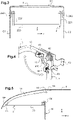
- the picture 3 illustrates an example of a front gallery 2 mounted between the side walls C1, C2, of the body structure, at the top of the vehicle, close to the foot cross member TC.
- Said gallery consists of a transverse bar 220 adapted to the width of the vehicle, extended integrally at one of its ends by a first vertical side bar 221 and at its opposite end by a second vertical side bar 222.
- Such gallery can be for example a U-shaped bent metal tube.
- said crossbar 220 receives the loads, and the vertical bars make it possible to retain the loads laterally while forming the support arms of the crossbar and receivers of the means of attachment to the vehicle.
- Each vertical bar 221, 222 is provided at its upper end with a support 240, 250 for securing to the body wall which is provided with a transverse pivot axis allowing the pivoting of said gallery around said pivot axis, reversibly, for the move from a low position, corresponding to the use position, to a raised position, following an angular displacement of approximately 90 degrees from the low position, and corresponding to the non-use position.
- Each securing support interfaces between the roof rack and a body wall.
- the supports can be simple supports.
- the support could for example be a support mounted articulated on the body wall with position locking means.
- the roof rack comprises a device for securing to a side wall of the vehicle, making the roof rack pivotable and incorporating a locking/unlocking mechanism for the positions of use and non-use of the roof rack.
- the gallery 1 is formed of a bent tube comprising a rectilinear transverse part, forming the transverse bar receiving the loads and extended at each end, at the level of the curvature of the tube, by vertical arms 12 which are secured at their respective end to the side walls of the vehicle body.
- the roof rack is illustrated, partially, in the lowered position and in the raised position at 90 degrees.
- the securing means comprise a mounting lug 40 having a through hole and to which is added a guide and locking device 41 in the form of a sector.
- Said device 41 comprises an axis hole which comes into correspondence with the orifice of the bracket and through which passes a bolt 42 (or screw), and said bolt having been previously inserted into a hole drilled in the tubular arm 12 of the gallery.
- Said sector-shaped guide and locking device 41 also has a guide groove 410, in the shape of an arc of a circle, which guides the head of a spring-loaded pusher 43 fixed through the tubular arm of the gallery, the spring being on the opposite side to the sector shape and placed in abutment against a plate 44 fixed to said arm.
- the head of the pusher is located at the opposite end to that surrounded by the spring, and is on the side of said guide groove 410.
- Said groove comprises at each end a recessed housing in which the head of the pusher is housed, the housings corresponding respectively at the low position and at the raised position of the gallery. The housings are thus positioned at the end of travel of the angular displacements of the gallery in the longitudinal directions X+ or X-.
- the spring of the pusher compresses under this push so that the head of the pusher comes out of its housing at the end of the guide groove of the sector to then be guided along the arc of said groove until it reaches the other housing, the spring relaxes and the head is then held by the force of the relaxed spring in said other housing.
- the two lower and raised positions of the roof rack can thus be locked.
- the roof racks are mounted according to the representations illustrated respectively in figures 3 and 4 .
- the galleries are joined together by an articulated coupling device 50 in order to make their movements in rotation synchronous and thus put them simultaneously in the position of non-use, the figures 2A to 2C showing the progress of the move.
- the rear gallery 1 which is the main gallery, is mounted at the end of at least one of its arms 12 on a device for securing to the body wall incorporating a guide device and locking such as the sector-shaped device 41 cooperating with the push button 43 on the arm of the gallery.
- said gallery is connected at said arm 12 to an articulated coupling device 50.
- Said coupling device 50 comprises a first rod 510 and a second rod 520 which are connected at one of their ends to each other. in an articulated manner on a transverse axis of rotation, the other end of the first rod 510 being connected by articulation on an axis of rotation to an arm 12 of the rear gallery 1, and the end of the second rod being connected to a arm 222 of the front gallery 2, on the same side as the connected arm of the master gallery 1, at a point one higher than that of connection between the first rod and the rear gallery.
- the first rod 510 connected to the rear and main gallery 1 is longer than the second rod 520 connected to the front gallery 2.
- the gallery pivots by guiding in the guide groove 410 of its guiding and locking device 41 towards its raised position, at 90 degrees from its low position of use.
- the first rod 510 of the coupling device transmits the rotational movement imparted on the rear roof rack 1 causes the second rod of the coupling device to tilt, which will then push the front roof rack 2, the latter pivoting in turn following its mounting device on the box wall.
- the two galleries are thus in the raised position, horizontally, at the same time, according to a synchronized movement, the operator having only to act on one of the galleries, according to the example on the rear gallery 1
- the force thus exerted unlocks the position of the gallery 1 and the coupling device 50 then drives the front roof rack 2 to rotate it from the horizontal plane to the vertical plane.
- An advantage of the invention is that the roof racks can be folded up in the vehicle without having to disassemble them or store them, and that their positioning for non-use is done in a single maneuver, and the same for their positioning 'use.
- the device is easy to implement by a user thanks to the locking system integrated into the securing supports.
- Another advantage of the invention is the installation of the roof racks in the upper part of the vehicle, close to the feet and the foot crosspieces, so that the roof racks in the non-use position, that is to say raised at horizontal, occupy the space between the foot rails which is a space not usually used.
- the non-use gallery structure thus occupies a dead volume of the vehicle, and does not create additional space.
- the feet and foot crosspieces that reinforce the body structure can be sized according to the use of the vehicle and the weight of the loads that the vehicle is authorized to transport.
- the galleries that is to say to have two galleries abutting one another in the same direction, i.e. the transverse direction of the vehicle, supported by a central support to which the sides of said two abutting roof racks are attached to separate the deployment of the roof racks on the right side of the vehicle from those on the left side.
- said central support is common to said two galleries, said support integrating a pivot axis making it possible to move said two abutting galleries by pivoting.
- Said central support of the galleries is preferably fixed on the body structure, in a zone substantially centered on the foot crosspieces.
- the galleries are also on their other side secured to a side wall of the vehicle, for example according to the modes described above.
- FIG 5 is illustrated an example of a load-bearing front element 3 of said interior load-bearing assembly, which is arranged as an extension of the galleries which have just been described, this arrangement taking place in particular in the passenger compartment above one or more passengers.
- This front load support element 3 is a box which makes it possible to transport, and if necessary to store, objects above the head of the passenger and/or the driver.
- This box can be preformed in plastic, for example in polypropylene.
- This box-shaped element comprises a lower wall 30 which is preferably horizontal and extends into an upper wall 31 which substantially matches the internal shape of the pavilion.
- this box-shaped element In front of this box-shaped element is a set of indexing pins 61 which participate in the centering (indexing) of the box on the roof crosspiece TP.
- a metal insert 60 making it possible to stiffen said element.
- This insert also makes it possible to fix the partition W between the passenger compartment and the utility part of the vehicle, said partition being lower than for a vehicle not equipped with the storage unit.
- a flat zone 62 which makes it possible to fix said element on the foot crosspiece TB. Isostatism is thus ensured.
- This box-shaped element thus advantageously extends the galleries for transporting and storing objects.
Landscapes
- Engineering & Computer Science (AREA)
- Mechanical Engineering (AREA)
- Vehicle Step Arrangements And Article Storage (AREA)
- Body Structure For Vehicles (AREA)
- Passenger Equipment (AREA)
Claims (11)
- Innenraumanordnung zum Tragen von Lasten, die im oberen Innenraumteil eines Fahrzeugs angeordnet ist und wenigstens einen ersten und einen zweiten Träger (1, 2) zum Tragen von Lasten umfasst, die mit einer Vorrichtung zur festen Verbindung mit dem Innenraum des Fahrzeugs ausgestattet sind und so angebracht sind, dass sie durch Schwenken aus einer Verwendungsposition in eine Nicht-Verwendungsposition und umgekehrt verlagert werden können, wobei die Träger durch Kopplungsmittel (50) fest miteinander verbunden sind, derart, dass die Verlagerung eines der Träger beim umkehrbaren Übergang aus einer Verwendungsposition in eine Nicht-Verwendungsposition die Verlagerung des anderen Trägers zur Folge hat, dadurch gekennzeichnet, dass die Mittel zur Kopplung (50) zwischen den Trägern eine erste Stange (510) und eine zweite Stange (520) umfassen, die jeweils an ihrem einen Ende miteinander gelenkig verbunden sind, wobei die erste Stange an ihrem anderen Ende mit dem ersten Träger gelenkig verbunden ist und die zweite Stange an ihrem anderen Ende starr mit dem zweiten Träger verbunden ist.
- Anordnung nach Anspruch 1, dadurch gekennzeichnet, dass der erste Träger (1) eine Vorrichtung zur Verriegelung seiner Verwendungs- und seiner Nicht-Verwendungsposition umfasst.
- Anordnung nach Anspruch 1, dadurch gekennzeichnet, dass die erste Stange (510) eine größere Länge als die zweite Stange (520) aufweist.
- Anordnung nach einem der Ansprüche 1 bis 3, dadurch gekennzeichnet, dass in wenigstens eine der Vorrichtungen zur festen Verbindung des ersten Trägers mit dem Innenraum des Fahrzeugs die Mittel zur Verriegelung der Verwendungs- und der Nicht-Verwendungsposition integriert sind.
- Anordnung nach Anspruch 4, dadurch gekennzeichnet, dass der erste Träger (1) eine Querstange umfasst, die an jedem ihrer Enden durch einen seitlichen Arm (12) verlängert ist, der mit einer Drucktaste (43) ausgestattet ist, und die Mittel zur festen Verbindung eine Führungs- und Verriegelungsvorrichtung (41) von der Form eines Sektors umfassen, der eine Nut zur Führung (410) des Kopfes der Taste (43) aufweist, wobei die Nut die Form eines Kreisbogens hat, welcher an jedem Ende eine vertiefte Aufnahme aufweist, die den Kopf der Taste aufnimmt und der Verwendungs- bzw. der Nicht-Verwendungsposition des Trägers entspricht.
- Anordnung nach einem der Ansprüche 1 bis 5, dadurch gekennzeichnet, dass die Träger schwenkbar angebracht sind, um durch Schwenkung mittels einer Winkelverschiebung um 90 Grad umkehrbar aus einer Verwendungsposition in eine Nicht-Verwendungsposition verlagert zu werden.
- Anordnung nach einem der Ansprüche 1 bis 6, dadurch gekennzeichnet, dass sie in Verlängerung der Träger (1, 2) ein Ablageelement (3) umfasst, dass die Form eines Kastens aufweist, der eine untere Wand (30) aufweist, die im Wesentlichen horizontal ist und sich in einer oberen Wand (31) fortsetzt, welche im Wesentlichen an die innere Form des Daches (T) des Fahrzeugs angepasst ist.
- Nutzfahrzeug, dadurch gekennzeichnet, dass es in seinem oberen Innenraumteil eine Innenraumanordnung zum Tragen von Lasten, wie in einem der Ansprüche 1 bis 7 definiert, umfasst, wobei die Träger (1, 2) der Anordnung im Nutzlastteil des Fahrzeugs eingebaut sind, in der Nähe der Stützen (C, D) und Querstreben (TC, TD) der Stützen des Fahrzeugs.
- Nutzfahrzeug nach Anspruch 8, dadurch gekennzeichnet, dass der erste Träger (1) von den Trägern derjenige Träger ist, der sich im Fahrzeug am weitesten hinten befindet.
- Nutzfahrzeug nach einem der Ansprüche 8 oder 9, dadurch gekennzeichnet, dass das Ablageelement (3) der Anordnung in der Verlängerung der Träger (1, 2) im oberen Teil des Fahrzeuginnenraums angeordnet ist.
- Nutzfahrzeug nach Anspruch 10, dadurch gekennzeichnet, dass das Ablageelement zwischen zwei Querstreben von Stützen des Fahrzeugs (TP, TB) befestigt ist.
Applications Claiming Priority (2)
| Application Number | Priority Date | Filing Date | Title |
|---|---|---|---|
| FR1760799A FR3073474B1 (fr) | 2017-11-16 | 2017-11-16 | Ensemble interieur support de charges d'un vehicule |
| PCT/EP2018/079065 WO2019096550A1 (fr) | 2017-11-16 | 2018-10-23 | Ensemble interieur support de charges, se disposant en partie interieure haute du vehicule |
Publications (2)
| Publication Number | Publication Date |
|---|---|
| EP3710311A1 EP3710311A1 (de) | 2020-09-23 |
| EP3710311B1 true EP3710311B1 (de) | 2022-04-27 |
Family
ID=60955272
Family Applications (1)
| Application Number | Title | Priority Date | Filing Date |
|---|---|---|---|
| EP18789423.3A Active EP3710311B1 (de) | 2017-11-16 | 2018-10-23 | Innenraumanorndung zum tragen von lasten im oberen fahrzeuginnenraumteil |
Country Status (5)
| Country | Link |
|---|---|
| EP (1) | EP3710311B1 (de) |
| JP (1) | JP2021503407A (de) |
| CN (1) | CN111356612B (de) |
| FR (1) | FR3073474B1 (de) |
| WO (1) | WO2019096550A1 (de) |
Families Citing this family (2)
| Publication number | Priority date | Publication date | Assignee | Title |
|---|---|---|---|---|
| FR3141118B1 (fr) * | 2022-10-19 | 2024-09-06 | Renault Sas | Support de charge à l’intérieur d’un véhicule automobile. |
| CN115817349A (zh) * | 2023-01-05 | 2023-03-21 | 北京汽车集团越野车有限公司 | 车辆行李架和具有其的车辆 |
Citations (1)
| Publication number | Priority date | Publication date | Assignee | Title |
|---|---|---|---|---|
| US3534892A (en) * | 1968-05-01 | 1970-10-20 | Edward L Truelove Sr | Utility rack for station wagons or the like |
Family Cites Families (8)
| Publication number | Priority date | Publication date | Assignee | Title |
|---|---|---|---|---|
| FR2682657B1 (fr) * | 1991-10-21 | 1997-10-03 | Peugeot | Agencement pour le transport d'un objet de grande longueur a l'interieur d'un vehicule automobile. |
| JP2824047B2 (ja) * | 1996-07-31 | 1998-11-11 | 西川化成株式会社 | 自動車用ルーフキャリア |
| FR2880599B1 (fr) * | 2005-01-13 | 2008-12-26 | Wagon Sas | Dispositif de portage interieur pour vehicule automobile et vehicule correspondant |
| ITTO20060667A1 (it) * | 2006-09-19 | 2008-03-20 | Fiat Auto Spa | Gruppo sedile-paratia, in particolare per un veicolo commerciale, e veicolo commerciale provvisto di tale gruppo sedile-paratia |
| GB2441989B (en) * | 2006-09-21 | 2011-09-07 | Ford Global Tech Llc | An overhead storage compartment for a vehicle |
| DE102007037212A1 (de) * | 2007-08-07 | 2009-02-12 | GM Global Technology Operations, Inc., Detroit | Kraftfahrzeug mit einem fahrzeugdachseitigen Gepäckträger im Fahrzeuginnenraum |
| FR2927031B1 (fr) * | 2008-01-31 | 2010-06-04 | Peugeot Citroen Automobiles Sa | Galerie interieure |
| DE102014109698B3 (de) * | 2014-05-14 | 2015-10-22 | Webasto SE | Anordnung mit einem Deckel für ein Fahrzeugdach |
-
2017
- 2017-11-16 FR FR1760799A patent/FR3073474B1/fr not_active Expired - Fee Related
-
2018
- 2018-10-23 JP JP2020526965A patent/JP2021503407A/ja active Pending
- 2018-10-23 EP EP18789423.3A patent/EP3710311B1/de active Active
- 2018-10-23 CN CN201880074285.XA patent/CN111356612B/zh active Active
- 2018-10-23 WO PCT/EP2018/079065 patent/WO2019096550A1/fr not_active Ceased
Patent Citations (1)
| Publication number | Priority date | Publication date | Assignee | Title |
|---|---|---|---|---|
| US3534892A (en) * | 1968-05-01 | 1970-10-20 | Edward L Truelove Sr | Utility rack for station wagons or the like |
Also Published As
| Publication number | Publication date |
|---|---|
| WO2019096550A1 (fr) | 2019-05-23 |
| FR3073474B1 (fr) | 2019-10-18 |
| JP2021503407A (ja) | 2021-02-12 |
| CN111356612A (zh) | 2020-06-30 |
| CN111356612B (zh) | 2023-09-19 |
| EP3710311A1 (de) | 2020-09-23 |
| FR3073474A1 (fr) | 2019-05-17 |
Similar Documents
| Publication | Publication Date | Title |
|---|---|---|
| EP1778524B1 (de) | Sicherheitsvorrichtung zur verwendung im falle eines fahrzeugüberschlags | |
| FR2548106A1 (fr) | Siege auxiliaire pour vehicules | |
| FR2990167A1 (fr) | Siege, notamment pour vehicule automobile | |
| FR3051416B1 (fr) | Dispositif de separation entre un habitacle et un espace de chargement et vehicule equipe d'un tel dispositif | |
| EP3710311B1 (de) | Innenraumanorndung zum tragen von lasten im oberen fahrzeuginnenraumteil | |
| EP2285621B1 (de) | Anordnung für ein automobilheck und automobil mit einer solchen anordnung | |
| FR2829082A1 (fr) | Dispositif formant porte-velos pour le transport d'au moins une bicyclette transversalement a l'arriere d'un vehicule automobile | |
| FR2632580A1 (fr) | Dispositif a sieges escamotables pour vehicules | |
| WO2003013889A1 (fr) | Vehicule decouvrable a toit repliable | |
| EP2048033A1 (de) | Hebelgesteuertes, versenkbares Dachgepäckträgersystem für Kraftfahrzeug und entsprechendes Fahrzeug | |
| FR3010018A1 (fr) | Agencement d'un cloisonnement coulissant a l'interieur d'un vehicule dote d'un ouvrant | |
| EP1964712B1 (de) | Versenkbarer Sitz eines Kraftfahrzeugs | |
| EP3381753A1 (de) | Schwenkbare gurtschnalle | |
| CA1158278A (fr) | Amenagement interieur de vehicule tel que caravane pliante | |
| FR2865976A1 (fr) | Vehicule automobile comprenant un siege arriere repliable et escamotable. | |
| EP3888979B1 (de) | Versenkbarer fahrradträger | |
| FR3021001A1 (fr) | Vehicule automobile comportant des supports de siege retractables | |
| FR3141118A1 (fr) | Support de charge à l’intérieur d’un véhicule automobile. | |
| FR3129643A1 (fr) | Véhicule doté d’un espace de rangement modulable | |
| FR3024680A1 (fr) | Siege de vehicule automobile et vehicule automobile equipe d’un tel siege | |
| FR2922169A1 (fr) | Systeme de galerie escamotable pour vehicule automobile, commande par un levier, et vehicule correspondant | |
| EP3882082A1 (de) | Fahrzeug mit verbessertem schwenkarm | |
| FR3127918A1 (fr) | Chariot mobile porte-charge comportant un dispositif de verrouillage a l’interieur d’un vehicule de transport | |
| FR3155470A1 (fr) | Dispositif de partitionnement avec barre d’arrimage pour une carrosserie frigorifique | |
| FR3154667A1 (fr) | véhicule doté d’une rangée de sièges possédant un dossier déplaçable |
Legal Events
| Date | Code | Title | Description |
|---|---|---|---|
| STAA | Information on the status of an ep patent application or granted ep patent |
Free format text: STATUS: UNKNOWN |
|
| STAA | Information on the status of an ep patent application or granted ep patent |
Free format text: STATUS: THE INTERNATIONAL PUBLICATION HAS BEEN MADE |
|
| PUAI | Public reference made under article 153(3) epc to a published international application that has entered the european phase |
Free format text: ORIGINAL CODE: 0009012 |
|
| STAA | Information on the status of an ep patent application or granted ep patent |
Free format text: STATUS: REQUEST FOR EXAMINATION WAS MADE |
|
| 17P | Request for examination filed |
Effective date: 20200504 |
|
| AK | Designated contracting states |
Kind code of ref document: A1 Designated state(s): AL AT BE BG CH CY CZ DE DK EE ES FI FR GB GR HR HU IE IS IT LI LT LU LV MC MK MT NL NO PL PT RO RS SE SI SK SM TR |
|
| AX | Request for extension of the european patent |
Extension state: BA ME |
|
| DAV | Request for validation of the european patent (deleted) | ||
| DAX | Request for extension of the european patent (deleted) | ||
| STAA | Information on the status of an ep patent application or granted ep patent |
Free format text: STATUS: EXAMINATION IS IN PROGRESS |
|
| 17Q | First examination report despatched |
Effective date: 20210416 |
|
| GRAP | Despatch of communication of intention to grant a patent |
Free format text: ORIGINAL CODE: EPIDOSNIGR1 |
|
| STAA | Information on the status of an ep patent application or granted ep patent |
Free format text: STATUS: GRANT OF PATENT IS INTENDED |
|
| INTG | Intention to grant announced |
Effective date: 20211122 |
|
| RAP3 | Party data changed (applicant data changed or rights of an application transferred) |
Owner name: RENAULT S.A.S |
|
| GRAS | Grant fee paid |
Free format text: ORIGINAL CODE: EPIDOSNIGR3 |
|
| GRAA | (expected) grant |
Free format text: ORIGINAL CODE: 0009210 |
|
| STAA | Information on the status of an ep patent application or granted ep patent |
Free format text: STATUS: THE PATENT HAS BEEN GRANTED |
|
| AK | Designated contracting states |
Kind code of ref document: B1 Designated state(s): AL AT BE BG CH CY CZ DE DK EE ES FI FR GB GR HR HU IE IS IT LI LT LU LV MC MK MT NL NO PL PT RO RS SE SI SK SM TR |
|
| REG | Reference to a national code |
Ref country code: GB Ref legal event code: FG4D Free format text: NOT ENGLISH |
|
| REG | Reference to a national code |
Ref country code: CH Ref legal event code: EP |
|
| REG | Reference to a national code |
Ref country code: AT Ref legal event code: REF Ref document number: 1486712 Country of ref document: AT Kind code of ref document: T Effective date: 20220515 |
|
| REG | Reference to a national code |
Ref country code: DE Ref legal event code: R096 Ref document number: 602018034593 Country of ref document: DE |
|
| REG | Reference to a national code |
Ref country code: IE Ref legal event code: FG4D Free format text: LANGUAGE OF EP DOCUMENT: FRENCH |
|
| RAP4 | Party data changed (patent owner data changed or rights of a patent transferred) |
Owner name: RENAULT S.A.S |
|
| REG | Reference to a national code |
Ref country code: LT Ref legal event code: MG9D |
|
| REG | Reference to a national code |
Ref country code: NL Ref legal event code: MP Effective date: 20220427 |
|
| REG | Reference to a national code |
Ref country code: AT Ref legal event code: MK05 Ref document number: 1486712 Country of ref document: AT Kind code of ref document: T Effective date: 20220427 |
|
| PG25 | Lapsed in a contracting state [announced via postgrant information from national office to epo] |
Ref country code: NL Free format text: LAPSE BECAUSE OF FAILURE TO SUBMIT A TRANSLATION OF THE DESCRIPTION OR TO PAY THE FEE WITHIN THE PRESCRIBED TIME-LIMIT Effective date: 20220427 |
|
| PG25 | Lapsed in a contracting state [announced via postgrant information from national office to epo] |
Ref country code: SE Free format text: LAPSE BECAUSE OF FAILURE TO SUBMIT A TRANSLATION OF THE DESCRIPTION OR TO PAY THE FEE WITHIN THE PRESCRIBED TIME-LIMIT Effective date: 20220427 Ref country code: PT Free format text: LAPSE BECAUSE OF FAILURE TO SUBMIT A TRANSLATION OF THE DESCRIPTION OR TO PAY THE FEE WITHIN THE PRESCRIBED TIME-LIMIT Effective date: 20220829 Ref country code: NO Free format text: LAPSE BECAUSE OF FAILURE TO SUBMIT A TRANSLATION OF THE DESCRIPTION OR TO PAY THE FEE WITHIN THE PRESCRIBED TIME-LIMIT Effective date: 20220727 Ref country code: LT Free format text: LAPSE BECAUSE OF FAILURE TO SUBMIT A TRANSLATION OF THE DESCRIPTION OR TO PAY THE FEE WITHIN THE PRESCRIBED TIME-LIMIT Effective date: 20220427 Ref country code: HR Free format text: LAPSE BECAUSE OF FAILURE TO SUBMIT A TRANSLATION OF THE DESCRIPTION OR TO PAY THE FEE WITHIN THE PRESCRIBED TIME-LIMIT Effective date: 20220427 Ref country code: GR Free format text: LAPSE BECAUSE OF FAILURE TO SUBMIT A TRANSLATION OF THE DESCRIPTION OR TO PAY THE FEE WITHIN THE PRESCRIBED TIME-LIMIT Effective date: 20220728 Ref country code: FI Free format text: LAPSE BECAUSE OF FAILURE TO SUBMIT A TRANSLATION OF THE DESCRIPTION OR TO PAY THE FEE WITHIN THE PRESCRIBED TIME-LIMIT Effective date: 20220427 Ref country code: ES Free format text: LAPSE BECAUSE OF FAILURE TO SUBMIT A TRANSLATION OF THE DESCRIPTION OR TO PAY THE FEE WITHIN THE PRESCRIBED TIME-LIMIT Effective date: 20220427 Ref country code: BG Free format text: LAPSE BECAUSE OF FAILURE TO SUBMIT A TRANSLATION OF THE DESCRIPTION OR TO PAY THE FEE WITHIN THE PRESCRIBED TIME-LIMIT Effective date: 20220727 Ref country code: AT Free format text: LAPSE BECAUSE OF FAILURE TO SUBMIT A TRANSLATION OF THE DESCRIPTION OR TO PAY THE FEE WITHIN THE PRESCRIBED TIME-LIMIT Effective date: 20220427 |
|
| PG25 | Lapsed in a contracting state [announced via postgrant information from national office to epo] |
Ref country code: RS Free format text: LAPSE BECAUSE OF FAILURE TO SUBMIT A TRANSLATION OF THE DESCRIPTION OR TO PAY THE FEE WITHIN THE PRESCRIBED TIME-LIMIT Effective date: 20220427 Ref country code: PL Free format text: LAPSE BECAUSE OF FAILURE TO SUBMIT A TRANSLATION OF THE DESCRIPTION OR TO PAY THE FEE WITHIN THE PRESCRIBED TIME-LIMIT Effective date: 20220427 Ref country code: LV Free format text: LAPSE BECAUSE OF FAILURE TO SUBMIT A TRANSLATION OF THE DESCRIPTION OR TO PAY THE FEE WITHIN THE PRESCRIBED TIME-LIMIT Effective date: 20220427 Ref country code: IS Free format text: LAPSE BECAUSE OF FAILURE TO SUBMIT A TRANSLATION OF THE DESCRIPTION OR TO PAY THE FEE WITHIN THE PRESCRIBED TIME-LIMIT Effective date: 20220827 |
|
| REG | Reference to a national code |
Ref country code: DE Ref legal event code: R097 Ref document number: 602018034593 Country of ref document: DE |
|
| PG25 | Lapsed in a contracting state [announced via postgrant information from national office to epo] |
Ref country code: SM Free format text: LAPSE BECAUSE OF FAILURE TO SUBMIT A TRANSLATION OF THE DESCRIPTION OR TO PAY THE FEE WITHIN THE PRESCRIBED TIME-LIMIT Effective date: 20220427 Ref country code: SK Free format text: LAPSE BECAUSE OF FAILURE TO SUBMIT A TRANSLATION OF THE DESCRIPTION OR TO PAY THE FEE WITHIN THE PRESCRIBED TIME-LIMIT Effective date: 20220427 Ref country code: RO Free format text: LAPSE BECAUSE OF FAILURE TO SUBMIT A TRANSLATION OF THE DESCRIPTION OR TO PAY THE FEE WITHIN THE PRESCRIBED TIME-LIMIT Effective date: 20220427 Ref country code: EE Free format text: LAPSE BECAUSE OF FAILURE TO SUBMIT A TRANSLATION OF THE DESCRIPTION OR TO PAY THE FEE WITHIN THE PRESCRIBED TIME-LIMIT Effective date: 20220427 Ref country code: DK Free format text: LAPSE BECAUSE OF FAILURE TO SUBMIT A TRANSLATION OF THE DESCRIPTION OR TO PAY THE FEE WITHIN THE PRESCRIBED TIME-LIMIT Effective date: 20220427 Ref country code: CZ Free format text: LAPSE BECAUSE OF FAILURE TO SUBMIT A TRANSLATION OF THE DESCRIPTION OR TO PAY THE FEE WITHIN THE PRESCRIBED TIME-LIMIT Effective date: 20220427 |
|
| PLBE | No opposition filed within time limit |
Free format text: ORIGINAL CODE: 0009261 |
|
| STAA | Information on the status of an ep patent application or granted ep patent |
Free format text: STATUS: NO OPPOSITION FILED WITHIN TIME LIMIT |
|
| PG25 | Lapsed in a contracting state [announced via postgrant information from national office to epo] |
Ref country code: AL Free format text: LAPSE BECAUSE OF FAILURE TO SUBMIT A TRANSLATION OF THE DESCRIPTION OR TO PAY THE FEE WITHIN THE PRESCRIBED TIME-LIMIT Effective date: 20220427 |
|
| 26N | No opposition filed |
Effective date: 20230130 |
|
| PG25 | Lapsed in a contracting state [announced via postgrant information from national office to epo] |
Ref country code: SI Free format text: LAPSE BECAUSE OF FAILURE TO SUBMIT A TRANSLATION OF THE DESCRIPTION OR TO PAY THE FEE WITHIN THE PRESCRIBED TIME-LIMIT Effective date: 20220427 Ref country code: MC Free format text: LAPSE BECAUSE OF FAILURE TO SUBMIT A TRANSLATION OF THE DESCRIPTION OR TO PAY THE FEE WITHIN THE PRESCRIBED TIME-LIMIT Effective date: 20220427 |
|
| REG | Reference to a national code |
Ref country code: CH Ref legal event code: PL |
|
| REG | Reference to a national code |
Ref country code: BE Ref legal event code: MM Effective date: 20221031 |
|
| PG25 | Lapsed in a contracting state [announced via postgrant information from national office to epo] |
Ref country code: LU Free format text: LAPSE BECAUSE OF NON-PAYMENT OF DUE FEES Effective date: 20221023 |
|
| P01 | Opt-out of the competence of the unified patent court (upc) registered |
Effective date: 20230608 |
|
| PG25 | Lapsed in a contracting state [announced via postgrant information from national office to epo] |
Ref country code: LI Free format text: LAPSE BECAUSE OF NON-PAYMENT OF DUE FEES Effective date: 20221031 Ref country code: CH Free format text: LAPSE BECAUSE OF NON-PAYMENT OF DUE FEES Effective date: 20221031 |
|
| PG25 | Lapsed in a contracting state [announced via postgrant information from national office to epo] |
Ref country code: BE Free format text: LAPSE BECAUSE OF NON-PAYMENT OF DUE FEES Effective date: 20221031 |
|
| PG25 | Lapsed in a contracting state [announced via postgrant information from national office to epo] |
Ref country code: IE Free format text: LAPSE BECAUSE OF NON-PAYMENT OF DUE FEES Effective date: 20221023 |
|
| PG25 | Lapsed in a contracting state [announced via postgrant information from national office to epo] |
Ref country code: IT Free format text: LAPSE BECAUSE OF FAILURE TO SUBMIT A TRANSLATION OF THE DESCRIPTION OR TO PAY THE FEE WITHIN THE PRESCRIBED TIME-LIMIT Effective date: 20220427 |
|
| PG25 | Lapsed in a contracting state [announced via postgrant information from national office to epo] |
Ref country code: CY Free format text: LAPSE BECAUSE OF FAILURE TO SUBMIT A TRANSLATION OF THE DESCRIPTION OR TO PAY THE FEE WITHIN THE PRESCRIBED TIME-LIMIT Effective date: 20220427 |
|
| PG25 | Lapsed in a contracting state [announced via postgrant information from national office to epo] |
Ref country code: MK Free format text: LAPSE BECAUSE OF FAILURE TO SUBMIT A TRANSLATION OF THE DESCRIPTION OR TO PAY THE FEE WITHIN THE PRESCRIBED TIME-LIMIT Effective date: 20220427 Ref country code: HU Free format text: LAPSE BECAUSE OF FAILURE TO SUBMIT A TRANSLATION OF THE DESCRIPTION OR TO PAY THE FEE WITHIN THE PRESCRIBED TIME-LIMIT; INVALID AB INITIO Effective date: 20181023 |
|
| PG25 | Lapsed in a contracting state [announced via postgrant information from national office to epo] |
Ref country code: TR Free format text: LAPSE BECAUSE OF FAILURE TO SUBMIT A TRANSLATION OF THE DESCRIPTION OR TO PAY THE FEE WITHIN THE PRESCRIBED TIME-LIMIT Effective date: 20220427 |
|
| PG25 | Lapsed in a contracting state [announced via postgrant information from national office to epo] |
Ref country code: MT Free format text: LAPSE BECAUSE OF FAILURE TO SUBMIT A TRANSLATION OF THE DESCRIPTION OR TO PAY THE FEE WITHIN THE PRESCRIBED TIME-LIMIT Effective date: 20220427 |
|
| PG25 | Lapsed in a contracting state [announced via postgrant information from national office to epo] |
Ref country code: BG Free format text: LAPSE BECAUSE OF FAILURE TO SUBMIT A TRANSLATION OF THE DESCRIPTION OR TO PAY THE FEE WITHIN THE PRESCRIBED TIME-LIMIT Effective date: 20220427 |
|
| PG25 | Lapsed in a contracting state [announced via postgrant information from national office to epo] |
Ref country code: BG Free format text: LAPSE BECAUSE OF FAILURE TO SUBMIT A TRANSLATION OF THE DESCRIPTION OR TO PAY THE FEE WITHIN THE PRESCRIBED TIME-LIMIT Effective date: 20220427 |
|
| PGFP | Annual fee paid to national office [announced via postgrant information from national office to epo] |
Ref country code: DE Payment date: 20251021 Year of fee payment: 8 |
|
| PGFP | Annual fee paid to national office [announced via postgrant information from national office to epo] |
Ref country code: GB Payment date: 20251022 Year of fee payment: 8 |
|
| PGFP | Annual fee paid to national office [announced via postgrant information from national office to epo] |
Ref country code: FR Payment date: 20251030 Year of fee payment: 8 |