EP0834828B1 - Imprimante hybride équipée de plusieurs mécanismes d'impression, et sa méthode de contrôle - Google Patents
Imprimante hybride équipée de plusieurs mécanismes d'impression, et sa méthode de contrôle Download PDFInfo
- Publication number
- EP0834828B1 EP0834828B1 EP97115166A EP97115166A EP0834828B1 EP 0834828 B1 EP0834828 B1 EP 0834828B1 EP 97115166 A EP97115166 A EP 97115166A EP 97115166 A EP97115166 A EP 97115166A EP 0834828 B1 EP0834828 B1 EP 0834828B1
- Authority
- EP
- European Patent Office
- Prior art keywords
- printing mechanism
- printing
- state
- printer
- processing
- Prior art date
- Legal status (The legal status is an assumption and is not a legal conclusion. Google has not performed a legal analysis and makes no representation as to the accuracy of the status listed.)
- Expired - Lifetime
Links
Images



Classifications
-
- G—PHYSICS
- G06—COMPUTING OR CALCULATING; COUNTING
- G06K—GRAPHICAL DATA READING; PRESENTATION OF DATA; RECORD CARRIERS; HANDLING RECORD CARRIERS
- G06K15/00—Arrangements for producing a permanent visual presentation of the output data, e.g. computer output printers
- G06K15/02—Arrangements for producing a permanent visual presentation of the output data, e.g. computer output printers using printers
-
- B—PERFORMING OPERATIONS; TRANSPORTING
- B41—PRINTING; LINING MACHINES; TYPEWRITERS; STAMPS
- B41J—TYPEWRITERS; SELECTIVE PRINTING MECHANISMS, i.e. MECHANISMS PRINTING OTHERWISE THAN FROM A FORME; CORRECTION OF TYPOGRAPHICAL ERRORS
- B41J3/00—Typewriters or selective printing or marking mechanisms characterised by the purpose for which they are constructed
- B41J3/54—Typewriters or selective printing or marking mechanisms characterised by the purpose for which they are constructed with two or more sets of type or printing elements
- B41J3/546—Combination of different types, e.g. using a thermal transfer head and an inkjet print head
-
- G—PHYSICS
- G06—COMPUTING OR CALCULATING; COUNTING
- G06K—GRAPHICAL DATA READING; PRESENTATION OF DATA; RECORD CARRIERS; HANDLING RECORD CARRIERS
- G06K2215/00—Arrangements for producing a permanent visual presentation of the output data
- G06K2215/0082—Architecture adapted for a particular function
Definitions
- This invention relates to the control and configuration of a compound or hybrid printer, i.e., a printer having two or more printing mechanisms mounted therein.
- EP-A-0 652 533 discloses a printer having means for detecting the condition or states of the printer and for sending status information including a plurality of status bytes representing the detected states to a host device upon request from the latter.
- EP-A-0 654 757 discloses a similar printer additionally including an ASB (Automatic Status Back) function wherein the status of the printer is automatically sent to the host device in response to a change in any of the printer conditions represented by those status bytes. While both of these printers include a single printing mechanism they are capable of printing on a variety of different recording media, such as continuous or roll paper, slip forms, etc.. One of these recording media may be selected by a corresponding paper selection command from the host device.
- the status bytes include respective bytes related to those different recording media and indicating whether the respective recording medium is selected or not, is present or absent, or whether the printer is in a wait state waiting for the particular recording medium to be inserted.
- the status bytes further include an off-line cause status byte indicating the reason, if any, for an off-line state of the printer.
- Hybrid printers having two or more printing mechanisms as shown in FIG. 3 have been developed in recent years. Examples of hybrid printers are disclosed in JP-A-5-124278, JP-Y-5-12863, JP-A-4-148953 and EP-A-0 785 080 (the latter forming prior art according to Art. 54(3) EPC).
- a printer according to the preamble of claim 1 is known from US-A-4,874,264.
- Such hybrid printer 1 typically has non-impact type thermal printing mechanism 10 and impact type wire dot printing mechanism 20 as well as control circuit 30 for controlling both printing mechanisms 10 and 20 based on data transferred from a host device.
- Thermal printing mechanism 10 comprises thermal head 11, paper feed roller 13 for feeding thermal paper (roll paper) 12 to thermal head 11, and paper feed motor 14 and speed reducing gear 15 for driving paper feed roller 13.
- Wire dot printing mechanism 20 comprises print head (wire dot head) 24 disposed opposite platen 21 with ink ribbon 22 between them and moved left and right (perpendicular to the plane of the drawing in Fig. 3) by carriage 23 driven by a motor not shown in the figure, paper feed roller 26 for feeding slip form 25 to this print head 24, feed motor 27 and a gear set for driving paper feed roller 26.
- thermal printing mechanism 10 In this type of hybrid printer 1, customer receipts, for example, are printed on thermal paper 12, which is provided in rolls, using thermal printing mechanism 10, and slip forms 25 such as checks and vouchers are printed using wire dot printing mechanism 20.
- thermal printing mechanism 10 additionally for printing journals for preserving store sales records
- wire dot printing mechanism 20 additionally to perform authentication printing, in which case four types of printing could be performed by one printer.
- thermal printing mechanism 10 since feeding of the paper in thermal printing mechanism 10 is performed by turning the platen (formed by paper feed roller 13), it is desirable to stop printing immediately when it is detected that cover 19 has been opened and the platen has moved away from the paper, but since printing can be continued in wire dot printing mechanism 20 even if opening of cover 29 is detected, if it is for a short period, it is desirable to complete printing of the line being printed in order to preserve data.
- a busy signal is output when one of the covers (19, 29) is opened in a prior art hybrid printer, data can no longer be transferred from the host device to the printer even if the printing mechanism whose cover has not been opened can still be used. Therefore, in order to effectively utilize a plurality of printing mechanisms integrated in one hybrid printer, it is desirable to output a busy signal taking the respective states of the printing mechanisms into consideration.
- a hybrid printer is configured such that it pays attention to only the state of the printing mechanism selected by the host device and another printing mechanism cannot hinder processing by the printer as a whole. This allows the host device to be notified of the state of the printing mechanism selected by the host device, and therefore the operation of the host device is not affected by the state of printer mechanisms other than the selected printing mechanism.
- the selection means may select the printing mechanism to perform printing processing based on the data received from the host device.
- By notifying the host device of the state of the printing mechanism that will perform printing processing it becomes possible for the host device to perform appropriate processing such as immediately stopping the transmission of print data in the event there is a problem with said printing processing, thus improving data integrity.
- the interface circuit which manifests off-line or on-line, notify the host device. This facilitates real-time processing by the hardware, thus further enhancing data integrity.
- the selection means By making the selection means responsive to a first command for selecting the printing mechanism to perform printing processing and a second command for selecting the printing mechanism that is the subject of state notification it is possible to independently select the printing mechanism to perform printing processing and the printing mechanism whose state is to be notified, which makes it possible to notify the host device of the state of other printing mechanisms even during printing processing. Therefore, since the state of other printing mechanisms can be considered when determining the next printing processing, jobs can be efficiently allocated.
- the selection means uses a correspondence table that stores the correspondence between the printing mechanisms and the type or types of recording medium on which each printing mechanism prints for selecting a printing mechanism based on a recording medium selection command. This makes it possible to maintain compatibility at the command level with prior art printers that use a single printing mechanism, thus allowing the host device to control the printer device without recognizing the difference between printing mechanisms.
- hybrid printer 1 comprising thermal printing mechanism 10 and wire dot printing mechanism 20 shown in FIG. 3.
- hybrid printer 1 is connected to host device 2 and operates based on data transmitted from host device 2.
- Hybrid printer 1 comprises interface 51 connected to host device 2, and when data is received at interface 51, an interrupt is generated and data receiver 52 receives the data from interface 51.
- the data obtained from interface 51 pass through real-time command analyzer 53 during the processing of this interrupt. After having been analyzed, the data including commands and print data are stored in receive buffer 54.
- real-time command analyzer 53 When real-time command analyzer 53 recognizes a real-time command in the data from data receiver 52, it causes a pre-defined process corresponding to the recognized real-time command to be executed. Thus, when host device 2 sends a real-time command, the real-time command is detected before being transferred to receive buffer 54, and the process determined by this real-time command, such as changing the paper selection or sending the status data of the printer to the host device via data transmitter 56, can be immediately executed.
- Data stored in receive buffer 54 is extracted piece by piece and each piece of data is analyzed by command analyzer 55. If the analyzed data code is a control command, then the processing corresponding to that command is executed by controller 57.
- the printing mechanism to be used for printing the data is selected by printing mechanism selector 71 based on the type of paper previously selected by a paper selection command from host device 2.
- printing mechanism selector 71 selects the printing mechanism based on a table including the correspondence between various paper types, e.g., slip form or customer receipt, and the printing mechanism to be used with each paper type (see the Table below).
- the data is then stored in a print buffer of the selected printing mechanism.
- the print data may either be text data, i.e., in the form of character codes, or graphics data, i.e., image data.
- the character codes are developed into image data by a character generator or other known means (assumed to be part of controller 57 in this embodiment) before they are stored in the print buffer.
- a character generator or other known means assumed to be part of controller 57 in this embodiment
- controller 57 controls the printing device 62 or 64 of the selected printing mechanism, i.e., thermal printing mechanism 10 or wire dot printing mechanism 20, to print the data form the selected print buffer 61 or 63.
- Each printing device may have a known configuration comprising a print head, paper feed mechanism, inking device, and other components such as a paper cutter.
- a separate print buffer is provided for each printing mechanism.
- the invention can be realized according to another embodiment, shown in Fig. 2, by using a common print buffer 67 for both (all) printing mechanisms. In this case, until the printing processing of one printing mechanism is completed, printing processing by the other printing mechanism(s), including developing character codes into image data, is kept in a standby state. If the printing mechanisms are different, the print head configurations and the number of dots making up one character may be different, in which case it is desirable to provide each printing mechanism with its own character generator for developing character codes into image data. In the embodiment shown in FIG.
- thermal printing mechanism 10 is provided with character generator 68 and wire dot printing mechanism 20 is provided with character generator 69.
- character codes among the print data received are first converted to image data by the respective character generator 68, 69, are then stored in the common print buffer 67 and finally applied to the respective printing device 62, 64.
- a third embodiment of the invention may have the two separate print buffers of Fig. 1 and the two separate character generators of Fig. 2. Incidentally, except for the differences mentioned above, the embodiments of Figs. 1 and 2 are identical so that most of the foregoing explanation with respect to Fig. 1 applies to Fig. 2 in the same way and the following description applies to both figures except if stated otherwise.
- controller 57 When printing processing is performed by one of the printing mechanisms, controller 57 notifies processor 72, which serves both as error processing means and state determination means and is described below, that printing is in progress. This notification is performed by setting a corresponding print flag, for example.
- printer 1 of the embodiments described above is controlled such that thermal printing mechanism 10 and wire dot printing mechanism 20 do not perform printing processing at the same time.
- Printer 1 of the embodiments described above further has thermal printer state detector 65 and wire dot printer state detector 66 for detecting the states of thermal printing mechanism 10 and dot printing mechanism 20, respectively, by means of respective sensors.
- Thermal printer state detector 65 is configured to detect states such as opening and closing of cover 19 of thermal printing mechanism 10, paper jams and other errors, and, by means of near-end sensor 18 shown in FIG. 3, the end of a paper roll.
- Wire dot printer state detector 66 is configured to detect states such as opening and closing of cover 29 of wire dot printing mechanism 20, errors such as paper jams and overheating of print head 24, presence or absence of slip forms (by means of paper sensor 28 shown in FIG. 3), and the end of the ink ribbon (by ink ribbon sensor 22a shown in FIG. 3).
- the states detected by these state detectors are stored as status information in memory.
- the status information may be in the form of a number of status bytes similar to those more fully described in EP-A-0 652 533.
- Among the status is a first type of bytes specific to a particular one of the recording media listed in the table above, as well as a second type of byte such as an off-line cause status byte indicating the reason, if any, for an off-line state of the hybrid printer as represented by a busy signal.
- Status information relating to a particular recording medium is independent from which printing mechanism is currently selected. For instance, if near-end sensor 18 detects the end of thermal paper 12 being near, a corresponding bit in a customer receipt paper status byte will be set. Since the thermal paper is used only by the thermal printing mechanism 10, the information conveyed by this bit is independent of whether printing mechanism 10 or 20 is the selected printing mechanism. On the other hand, the off-line cause status byte may be different depending on which printing mechanism is selected. One bit of this byte may represent, for instance, the open/closed state of the cover.
- Another bit may indicate whether or not there is a mechanical problem, such as a paper jam, a carriage motion error etc.. Since each of the printing mechanisms 10 and 20 has its cover and in each of the printing mechanisms there may or may not be a paper jam, the information about this type of state is meaningful only in relation to a particular printing mechanism. Therefore, in an embodiment of the invention the information represented by this latter kind of byte is that for the selected one of the printing mechanisms (or second selected printing mechanism as will be explained later).
- the status information is sent to the host device upon a status request command by the latter and automatically in response to a change in any of the detected states of or any of preselected ones of the detected states.
- a cause for an off-line state occurs and a busy signal is output there may still be unprocessed data in receive buffer 54.
- the status request command should be sent as a real-time command which is immediately executed rather than being queued in receive buffer 54 as mentioned above.
- State detectors 65 and 66 transmit information to processor 72 every time when there is a change in any of those states of printing mechanisms 10 and 20.
- Processor 72 can judge the printing mechanism selected by printing mechanism selector 71. Therefore, processor 72 is able to determine the state of each printing mechanism 10 and 20 separately and also to determine whether or not a printing mechanism is printing by referencing the associated print flag. By this it becomes possible, if an error state occurs, to determine the error processing that should be performed in printer 1. For example, processor 72 will perform the following error processing according to the selected printing mechanism when it is detected that. the cover of either printing mechanism 10 or 20 has been opened.
- step ST13 comprises stopping printing when thermal printing mechanism is printing as the error state is detected.
- recovery processing that restarts printing is performed in ST11 and the error flag is reset in ST12.
- the processing for setting the printer off-line is performed according to the flowchart shown in FIG. 4. That is, the selected printing mechanism is judged in ST1. When the thermal printing mechanism is selected, the thermal printer error flag is checked in ST3. If this flag is set, the off-line state is set in ST5. When the error flag is reset in ST3, the off-line state, if any, is canceled in ST4 and the on-line state is immediately set instead.
- Busy signal generator 73 responds to the off-line state by generating the busy signal sent to the host device via interface 51.
- wire dot printing mechanism 20 When an open cover (29) is detected in wire dot printing mechanism 20, on the other hand, and wire dot printing mechanism 20 is the selected printing mechanism and is performing printing processing, it is necessary to stop printing and retract print head 24 to the standby position in order to ensure correct printing processing. Therefore, data in print buffer 63 (or 67) can no longer be processed and processing of data received in receive buffer 54 cannot proceed. Therefore, like in mode 1, the printer is set off-line and a busy signal is output from busy signal generator 73, which prompts host device 2 via interface 51 to stop data transfer. Also, since wire dot printing mechanism 20 prints on slip forms, it may be necessary to set the form to the correct printing position since it may have been shifted while the cover was open. Therefore, even if the cover is closed, automatic recovery is not performed, rather this treated as a non-recoverable error, and printing is only resumed and the busy signal cleared when a reset command is sent from the host device.
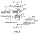
- FIG. 6 illustrating a routine which is invoked in the same manner as that of Fig. 5.
- an error state an open cover in this example
- an error processing is performed in ST26.
- An error flag associated with printing mechanism 20 is also set. If printing mechanism 20 is printing when the error state is detected, printing is stopped as a result of the error processing.
- known recovery processing such as detecting the home position of the carriage is performed.
- ST23 the printer waits for an error recovery command to be sent from the host device, and after it is received, printing is restarted in ST24 and the error flag is reset in ST25.
- the processing for setting the printer off-line is performed according to the flowchart in FIG. 4. That is, when the result in ST1 is that the wire dot printing mechanism is the selected printing mechanism, the error flag associated with this printing mechanism is checked in ST2. When the flag is set, the printer is set off-line in ST5. When the error flag is not set in ST2, the off-line state is canceled in ST4. That is, the on-line state is set instead.
- the host device is not notified of that state as an off-line state. That is, even if an open cover is detected in either thermal printing mechanism 10 or wire dot printing mechanism 20 and the associated error flag is set, no busy signal is output if the printer mechanism for which the error flag is set is not the selected printing mechanism.
- the state of each printing mechanism in the hybrid printer is detected, and error processing appropriate for the selected printing mechanism is quickly performed. Therefore, in addition to preventing problems specific to a particular printing mechanism such as a burned out print head, these embodiments allow the error processing optimum for the respective recording medium or paper to be performed.
- printing mechanism selector 71 selects thermal printing mechanism 10 in which case a busy signal is output only when a cause for a busy signal occurs in thermal printing mechanism 10.
- printing mechanism selector 71 selects wire dot printing mechanism 20 and a busy signal is output only when a cause for a busy signal occurs in wire dot printing mechanism 20. This makes it possible to efficiently utilize the printing mechanisms of the hybrid printer 1.
- hybrid printer 1 makes it possible to effectively utilize a plurality of printing mechanisms by allowing a printing mechanism to be used normally even if a problem has occurred in another printing mechanism as long as the other printing mechanism is not the selected one.
- the real-time commands it is possible to change the selection of a printing device even after a problem occurred in the previously selected printing device and caused a busy signal.
- the hybrid printer of the embodiments explained above allows the detection of the state of each printing mechanism separately, appropriate error processing can be performed for a printing mechanism. Also, since the cause of a busy signal can be judged and a busy signal output for only the selected printing mechanism, if a printing mechanism not giving a cause for a busy signal is selected it can receive data from the host device and perform printing processing. Therefore, even if one printing mechanism cannot be used for whatever reason, it is still possible to use the other printing mechanism(s), thus making it possible to take full advantage of the functions of the hybrid printer.
- the printing mechanism selection is realized by means of a control command (referred to as "paper selection command” herein) received from the host device and designating a recording medium to be printed and by referring to the look-up table shown and explained above.
- paper selection command a control command received from the host device and designating a recording medium to be printed and by referring to the look-up table shown and explained above.
- a preferred embodiment of the invention solves this problem by providing two types of paper selection command.
- a first type of these paper selection commands selects the recording medium to be printed on and, by the recording medium, the printing mechanism to used for the printing processing.
- the second type of paper selection command selects the recording medium and, by the recording medium, the printing mechanism whose status information is sent to the host device.
- a printing mechanism selected by the first type of paper selection command will be referred to as the "first selected” printing mechanism and a printing mechanism selected by the second type of paper selection command will be referred to as the "second selected” printing mechanism".
- the information which printing mechanism is the first selected one and which is the second selected one is stored in memory.
- two variables, FIRST and SECOND are stored to hold this information.
- both variables may be set independently, each in response to a respective one of the two types of paper selection command.
- both variables are set in accordance with the recording medium designated by that command. If subsequently the second type of paper selection command is received, the variable SECOND is set in accordance with the recording medium designated by this latter command while the variable FIRST remains unchanged.
- variable FIRST can be set and changed only by the first type of paper selection command while the variable SECOND is set and changed by each of the two types of command, i.e., reflects the last one of these two types of command.
- first type of paper selection command the first selected printing mechanism and the second selected printing mechanism are the same.
- the first selected printing mechanism and the second selected printing mechanism may be different ones.
- the second type of paper selection command may be also used to designate a recording medium for which control values, such as line spacing, margins etc., are to be set.
- control values such as line spacing, margins etc.
- the host device can get status information for one printing mechanism (the second selected printing mechanism) and then set or alter the control values to be used for controlling this printing mechanism to perform printing on the recording medium designated by the command while the other printing mechanism (the first selected one) is printing on another recording medium.
- step ST1 the selected printing mechanism is judged.
- the "selected” printing mechanism here means the “first selected” printing mechanism in the embodiment using two types of paper selection command. There may be cases, however, where it is desirable that the on-line/off-line state (as represented by absence/presence of the busy signal) represents the state of the printing mechanism whose status information is reported to the host device.
- the above mentioned second type of paper selection command not only select the printing mechanism whose status information is to be sent to the host device, but select this printing mechanism also as the one controlling the on-line/off-line state of the hybrid printer, i.e., the one judged to be the selected printing mechanism in step ST1 in Fig. 4.
Landscapes
- Engineering & Computer Science (AREA)
- General Engineering & Computer Science (AREA)
- Physics & Mathematics (AREA)
- General Physics & Mathematics (AREA)
- Theoretical Computer Science (AREA)
- Accessory Devices And Overall Control Thereof (AREA)
Claims (19)
- Imprimante hybride comprenant :une pluralité de mécanismes d'impression (10, 20) indépendants destinés à exécuter une impression basée sur des données reçues depuis un dispositif hôte (2), chaque mécanisme d'impression ayant sa propre tête d'impression (11, 24) et étant adapté pour imprimer sur un ou plusieurs types respectifs d'une pluralité de types de supports d'enregistrement (12, 25),un moyen de sélection (71) sensible à une instruction de commande prédéterminée incluse dans les données de façon à sélectionner l'un des mécanismes d'impression, caractérisée par :une pluralité de moyens de détection d'état (65, 66), associés chacun à l'un respectif des mécanismes d'impression afin de détecter des informations d'état relatives à ce mécanisme d'impression, etdes moyens de traitement d'état (51, 72, 73) sensibles au moyen de sélection afin de traiter les informations d'état dudit moyen de détection de la pluralité de moyens de détection d'état associé au mécanisme d'impression sélectionné par le moyen de sélection.
- Imprimante selon la revendication 1, dans laquelle le moyen de sélection (71) comprend une table de correspondance qui mémorise la correspondance entre les mécanismes d'impression (10, 20) et la pluralité de types de supports d'enregistrement (12, 25) et est sensible à une commande de sélection de support d'enregistrement pour sélectionner, en fonction de la table, le mécanisme d'impression adapté pour imprimer sur le support d'enregistrement sélectionné par la commande de sélection de support d'enregistrement.
- Imprimante selon la revendication 1 ou 2, dans laquelle les moyens de traitement d'état (51, 72, 73) comprennent un moyen d'indication d'état (51) destiné à communiquer au dispositif hôte les informations d'état relatives au mécanisme d'impression (10, 20) sélectionné.
- Imprimante selon la revendication 3, dans laquelle les informations d'état détectées par la pluralité de moyens de détection d'état (65, 66) comprennent un premier type d'état concernant uniquement l'un respectif des mécanismes d'impression (10, 20) et un deuxième type d'état concernant chaque mécanisme d'impression, dans laquelle le moyen d'indication d'état (51) est adapté pour communiquer au dispositif hôte le premier type d'état provenant de chaque moyen de la pluralité de moyens de détection et le deuxième type d'état provenant uniquement du moyen de détection associé au mécanisme d'impression sélectionné.
- Imprimante selon l'une quelconque des revendications précédentes, dans laquelle l'impression est exécutée par le mécanisme d'impression (10, 20) sélectionné.
- Imprimante selon l'une quelconque des revendications précédentes, dans laquelle les moyens de traitement d'état (51, 72, 73) comprennent en outre un moyen pour régler l'imprimante en état hors ligne en réponse à un état d'erreur détecté pour le mécanisme d'impression (10, 20) sélectionné et simultanément pour ne pas régler l'imprimante en état hors ligne en réponse à un état d'erreur détecté pour un mécanisme d'impression (10, 20) non sélectionné.
- Imprimante selon la revendication 3 ou 4, dans laquelle le moyen de sélection (71) est sensible à une première instruction de commande pour sélectionner un premier desdits mécanismes d'impression (10, 20) pour exécuter l'impression et sensible à une deuxième instruction de commande pour sélectionner un deuxième desdits mécanismes d'impression, dans laquelle les informations d'état communiquées par le moyen d'indication incluent les informations d'état relatives au premier mécanisme d'impression sélectionné quand aucun deuxième mécanisme d'impression n'a été sélectionné et relatives au deuxième mécanisme d'impression sélectionné quand un deuxième mécanisme d'impression a été sélectionné.
- Imprimante selon les revendications 6 et 7, dans laquelle le moyen destiné à régler l'imprimante en état hors ligne est sensible à un état d'erreur détecté pour le premier mécanisme d'impression (10, 20) sélectionné.
- Imprimante selon l'une quelconque des revendications précédentes, comprenant en outre un moyen de traitement d'erreur (72) sensible à un état d'erreur pour exécuter un traitement d'erreur par rapport et adapté au mécanisme d'impression (10, 20) pour lequel l'état d'erreur est détecté.
- Imprimante selon l'une quelconque des revendications 3 à 9, dans laquelle le moyen d'indication d'état (51) est un circuit d'interface qui présente un état hors ligne ou en ligne.
- Procédé pour commander une imprimante hybride comprenant une pluralité de mécanismes d'impression (10, 20) indépendants destinés à exécuter une impression basée sur des données reçues depuis un dispositif hôte (2), chaque mécanisme d'impression ayant sa propre tête d'impression (11, 24) et étant adapté pour imprimer sur un ou plusieurs types respectifs d'une pluralité de types de supports d'enregistrement (12, 25), le procédé comprenant l'étape consistant à :(a) sélectionner, en réponse à une instruction de commande prédéterminée incluse dans les données, l'un des mécanismes d'impression, et étant caractérisé par les étapes supplémentaires consistant à :(b) obtenir indépendamment pour chaque mécanisme d'impression les informations d'état relatives au mécanisme d'impression concerné, et(c) traiter les informations d'état correspondant uniquement audit mécanisme d'impression sélectionné par le moyen de sélection.
- Procédé selon la revendication 11, dans lequel l'étape (a) comprend(a1) la réception d'une instruction de commande de sélection de support d'enregistrement désignant un type de la pluralité de types de supports d'enregistrement, et(a2) la recherche, à partir d'une table de correspondance, qui stocke la correspondance entre les mécanismes d'impression (10, 20) et la pluralité de types de supports d'enregistrement (12, 25), du mécanisme d'impression correspondant au type désigné de support d'enregistrement et la sélection de ce mécanisme d'impression.
- Procédé selon la revendication 11 ou 12, dans lequel l'étape (c) comprend le fait de communiquer au dispositif hôte les informations d'état relatives au mécanisme d'impression (10, 20) sélectionné.
- Procédé selon la revendication 13, dans lequel l'étape (b) comprend le fait de détecter un premier type d'état concernant uniquement l'un respectif des mécanismes d'impression (10, 20) et un deuxième type d'état concernant chaque mécanisme d'impression, et l'étape (c) comprend le fait de communiquer au dispositif hôte le premier type d'état pour chacun des mécanismes d'impression respectifs et le deuxième type d'état uniquement pour le mécanisme d'impression sélectionné.
- Procédé selon l'une quelconque des revendications 11 à 14, dans lequel l'impression est exécutée par le mécanisme d'impression sélectionné.
- Procédé selon l'une quelconque des revendications 11 à 15, dans lequel l'étape (c) comprend en outre le réglage de l'imprimante en état hors ligne en réponse à un état d'erreur détecté pour le mécanisme d'impression (10, 20) sélectionné.
- Procédé selon la revendication 13 ou 14, dans lequel l'étape (a) comprend le fait de sélectionner, en réponse à une première instruction de commande, un premier desdits mécanismes d'impression (10, 20) pour exécuter l'impression et de sélectionner, en réponse à une deuxième instruction de commande, un deuxième desdits mécanismes d'impression, dans lequel l'étape (c) comprend le fait de communiquer au dispositif hôte les informations d'état relatives au premier mécanisme d'impression sélectionné quand aucun deuxième mécanisme d'impression n'a été sélectionné et relatives au deuxième mécanisme d'impression sélectionné quand un deuxième mécanisme d'impression a été sélectionné.
- Procédé selon les revendications 16 et 17, dans lequel le réglage de l'imprimante en état hors ligne est effectué en réponse à un état d'erreur détecté pour le mécanisme d'impression (10, 20) sélectionné.
- Procédé selon l'une quelconque des revendications 11 à 18, comprenant en outre une étape consistant à exécuter un traitement d'erreur par rapport et adapté au mécanisme d'impression (10, 20) pour lequel un état d'erreur est détecté à l'étape (b).
Applications Claiming Priority (3)
| Application Number | Priority Date | Filing Date | Title |
|---|---|---|---|
| JP232325/96 | 1996-09-02 | ||
| JP23232596 | 1996-09-02 | ||
| JP23232596 | 1996-09-02 |
Publications (3)
| Publication Number | Publication Date |
|---|---|
| EP0834828A2 EP0834828A2 (fr) | 1998-04-08 |
| EP0834828A3 EP0834828A3 (fr) | 1999-02-03 |
| EP0834828B1 true EP0834828B1 (fr) | 2004-03-03 |
Family
ID=16937435
Family Applications (1)
| Application Number | Title | Priority Date | Filing Date |
|---|---|---|---|
| EP97115166A Expired - Lifetime EP0834828B1 (fr) | 1996-09-02 | 1997-09-02 | Imprimante hybride équipée de plusieurs mécanismes d'impression, et sa méthode de contrôle |
Country Status (5)
| Country | Link |
|---|---|
| US (1) | US5911527A (fr) |
| EP (1) | EP0834828B1 (fr) |
| KR (1) | KR100484336B1 (fr) |
| CN (1) | CN1126023C (fr) |
| DE (1) | DE69727875T2 (fr) |
Families Citing this family (24)
| Publication number | Priority date | Publication date | Assignee | Title |
|---|---|---|---|---|
| JPH10138614A (ja) * | 1996-11-08 | 1998-05-26 | Star Micronics Co Ltd | プリンタ |
| GB9807632D0 (en) * | 1998-04-14 | 1998-06-10 | Ncr Int Inc | Printing apparatus and method |
| JP2002052796A (ja) * | 2000-08-07 | 2002-02-19 | Riso Kagaku Corp | 孔版印刷装置およびその制御方法 |
| JP4362977B2 (ja) * | 2001-01-16 | 2009-11-11 | セイコーエプソン株式会社 | デバイス状態監視装置 |
| KR100579350B1 (ko) * | 2001-01-26 | 2006-05-12 | 세이코 엡슨 가부시키가이샤 | 인쇄 시스템, 감열식 프린터, 인쇄 제어 방법 및 정보 기록 매체 |
| JP2003022170A (ja) * | 2001-07-06 | 2003-01-24 | Canon Inc | 分散印刷制御装置、分散印刷システム、分散印刷方法、コンピュータ読み取り可能な記録媒体、及びコンピュータプログラム |
| US20040080776A1 (en) * | 2002-10-28 | 2004-04-29 | Garcia Elias S. | Image forming devices, imaging forming systems and image forming device operational methods |
| US7011464B2 (en) * | 2003-03-06 | 2006-03-14 | Toshiba Tec Kabushiki Kaisha | Apparatus for detecting an end portion of a recording medium |
| JP4251029B2 (ja) * | 2003-07-28 | 2009-04-08 | セイコーエプソン株式会社 | 印刷装置及びその制御方法 |
| ITTO20030909A1 (it) * | 2003-11-17 | 2005-05-18 | Olivetti Tecnost S P A Ora Olivett I Spa | Dispositivo per stampare scontrini mediante due unita' di stampa, in particolare su carta termica, e relativo metodo di stampa. |
| US7275881B2 (en) | 2004-10-15 | 2007-10-02 | Sanford, L.P. | Control of dual printing mechanisms |
| PL2067627T3 (pl) | 2004-10-22 | 2011-07-29 | Sanford Lp | Drukarka |
| JP4424200B2 (ja) * | 2004-12-28 | 2010-03-03 | ブラザー工業株式会社 | 印刷装置 |
| US7669531B2 (en) * | 2005-02-28 | 2010-03-02 | Dimatix, Inc. | Printing systems and methods |
| KR100765758B1 (ko) * | 2005-09-12 | 2007-10-15 | 삼성전자주식회사 | 잉크 카트리지 조립체 및 이를 구비한 잉크젯 화상형성장치 |
| US8279475B2 (en) * | 2008-05-27 | 2012-10-02 | Bixolon Co., Ltd. | Printing apparatus and method for processing real-time command using the printing apparatus |
| US8019256B2 (en) * | 2008-07-21 | 2011-09-13 | Xerox Corporation | Multi-mode long life monochrome printing system |
| JP2012528741A (ja) * | 2009-06-04 | 2012-11-15 | オセ−テクノロジーズ・ベー・ヴエー | 画像処理装置上で文書を処理するための方法 |
| JP5691335B2 (ja) | 2010-09-17 | 2015-04-01 | セイコーエプソン株式会社 | 媒体処理装置、媒体処理装置の制御方法、及び、プログラム |
| JP6065761B2 (ja) * | 2013-06-20 | 2017-01-25 | セイコーエプソン株式会社 | 制御装置、および、制御装置の制御方法 |
| JP6380433B2 (ja) * | 2016-03-15 | 2018-08-29 | ブラザー工業株式会社 | 印刷装置 |
| CN110481174B (zh) * | 2019-07-11 | 2022-03-29 | 厦门汉印电子技术有限公司 | 打印控制方法、装置、打印机及计算机可读存储介质 |
| CN114610585A (zh) * | 2022-03-28 | 2022-06-10 | 刘东宇 | 自助报告打印机任务管理控制器 |
| CN115230340A (zh) * | 2022-07-27 | 2022-10-25 | 深圳诺优学科技有限公司 | 智能标识系统打印机 |
Family Cites Families (13)
| Publication number | Priority date | Publication date | Assignee | Title |
|---|---|---|---|---|
| JPS5862056A (ja) * | 1981-10-08 | 1983-04-13 | Canon Inc | 記録装置 |
| JPS6049973A (ja) * | 1983-08-31 | 1985-03-19 | Ricoh Co Ltd | 印字装置 |
| US4874264A (en) * | 1983-05-12 | 1989-10-17 | Ricoh Company, Ltd. | Selective magnetic attachment of a print head to a drive belt |
| JPS6151363A (ja) * | 1984-08-21 | 1986-03-13 | Brother Ind Ltd | 複合プリンタ |
| JPS6151378A (ja) * | 1984-08-21 | 1986-03-13 | Brother Ind Ltd | 複合プリンタのリボン送り装置 |
| JPS63179776A (ja) * | 1987-01-22 | 1988-07-23 | Nec Corp | 複合プリンタ |
| JPH01242282A (ja) * | 1988-03-25 | 1989-09-27 | Tokyo Electric Co Ltd | プリンタ制御装置 |
| JP2837702B2 (ja) * | 1988-11-14 | 1998-12-16 | 株式会社リコー | 画像形成システム |
| JP2520862B2 (ja) * | 1989-03-08 | 1996-07-31 | シーメンス ニクスドルフ インフオルマチオーンス ジステーメ アクチエンゲゼルシヤフト | 少なくとも2つの空間的に互いに分離された印刷ステ―ションを備えた印刷装置 |
| JPH0611565A (ja) * | 1992-03-16 | 1994-01-21 | Etr Electron Technol Rump Gmbh | 超音波距離測定装置 |
| JP3483044B2 (ja) * | 1993-11-16 | 2004-01-06 | セイコーエプソン株式会社 | 印刷装置、印刷システム、及びステータス変化検出方法 |
| US5452959A (en) * | 1994-08-26 | 1995-09-26 | Ko-Pack Corporation | Apparatus for printing characters onto both surfaces of a sheet material |
| CN100381941C (zh) * | 1995-02-22 | 2008-04-16 | 佳能株式会社 | 图象形成设备、图象形成系统以及向图象形成装置输出图象信息的设备 |
-
1997
- 1997-09-01 CN CN97120590A patent/CN1126023C/zh not_active Expired - Lifetime
- 1997-09-02 US US08/922,037 patent/US5911527A/en not_active Expired - Lifetime
- 1997-09-02 EP EP97115166A patent/EP0834828B1/fr not_active Expired - Lifetime
- 1997-09-02 DE DE69727875T patent/DE69727875T2/de not_active Expired - Lifetime
- 1997-09-02 KR KR1019970045466A patent/KR100484336B1/ko not_active Expired - Fee Related
Also Published As
| Publication number | Publication date |
|---|---|
| KR19980024251A (ko) | 1998-07-06 |
| US5911527A (en) | 1999-06-15 |
| EP0834828A3 (fr) | 1999-02-03 |
| CN1178938A (zh) | 1998-04-15 |
| EP0834828A2 (fr) | 1998-04-08 |
| KR100484336B1 (ko) | 2005-08-31 |
| DE69727875D1 (de) | 2004-04-08 |
| CN1126023C (zh) | 2003-10-29 |
| DE69727875T2 (de) | 2005-01-20 |
Similar Documents
| Publication | Publication Date | Title |
|---|---|---|
| EP0834828B1 (fr) | Imprimante hybride équipée de plusieurs mécanismes d'impression, et sa méthode de contrôle | |
| US5800081A (en) | Printing apparatus and a control method therefor | |
| EP0652533B1 (fr) | Détection de l'état de fonctionnement d'une imprimante | |
| US7869063B2 (en) | Printing apparatus, printer control method, printer control program, and printing system | |
| US6205363B1 (en) | Printer and control method for obtaining printer status | |
| US8077331B2 (en) | Printer and printer control method | |
| KR100255889B1 (ko) | 통신 단말 및 그 제어방법 | |
| US7503712B2 (en) | Printing apparatus for selecting the appropriate error state mode according to the application type and user desired print results | |
| US6132117A (en) | Printing apparatus, control method therefor and medium for storing the control method | |
| JP4924748B2 (ja) | プリンタ、及び受信データの処理方法 | |
| US5758041A (en) | Output control method and apparatus | |
| EP0583891B1 (fr) | Dispositif et méthode de sortie | |
| EP0545732B1 (fr) | Dispositif pour imprimer des données binaires organisées en pages | |
| JPH10333856A (ja) | 通信端末およびその制御方法、並びに当該制御プログラムが記録されたコンピュータ読み取り可能な記録媒体 | |
| JPH10119391A (ja) | 複数のプリンタ機構を備えた複合印刷装置およびその制御方法 | |
| JP4865140B2 (ja) | プリンタ、受信データの処理方法及びプログラム | |
| JP2002178617A (ja) | 印刷装置及びその制御方法並びに該印刷装置を用いた情報処理装置 | |
| JP2001282394A (ja) | 通信端末装置、その制御方法及びその記録媒体 | |
| JP2002200804A (ja) | 印刷装置及びその制御方法並びに該印刷装置を用いた情報処理装置 | |
| JPH10283131A (ja) | プリンタ | |
| HK1014283B (en) | A printing apparatus and a control method therefor | |
| JPH09263026A (ja) | 画像形成装置 | |
| HK1014280B (en) | Detection of the condition of a printer | |
| JP2000039973A (ja) | 印字装置および印字システム |
Legal Events
| Date | Code | Title | Description |
|---|---|---|---|
| PUAI | Public reference made under article 153(3) epc to a published international application that has entered the european phase |
Free format text: ORIGINAL CODE: 0009012 |
|
| AK | Designated contracting states |
Kind code of ref document: A2 Designated state(s): CH DE FR GB IT LI NL SE |
|
| AX | Request for extension of the european patent |
Free format text: AL;LT;LV;RO;SI |
|
| PUAL | Search report despatched |
Free format text: ORIGINAL CODE: 0009013 |
|
| AK | Designated contracting states |
Kind code of ref document: A3 Designated state(s): AT BE CH DE DK ES FI FR GB GR IE IT LI LU MC NL PT SE |
|
| AX | Request for extension of the european patent |
Free format text: AL;LT;LV;RO;SI |
|
| 17P | Request for examination filed |
Effective date: 19990730 |
|
| AKX | Designation fees paid |
Free format text: CH DE FR GB IT LI NL SE |
|
| GRAP | Despatch of communication of intention to grant a patent |
Free format text: ORIGINAL CODE: EPIDOSNIGR1 |
|
| GRAS | Grant fee paid |
Free format text: ORIGINAL CODE: EPIDOSNIGR3 |
|
| GRAA | (expected) grant |
Free format text: ORIGINAL CODE: 0009210 |
|
| AK | Designated contracting states |
Kind code of ref document: B1 Designated state(s): CH DE FR GB IT LI NL SE |
|
| REG | Reference to a national code |
Ref country code: GB Ref legal event code: FG4D |
|
| REG | Reference to a national code |
Ref country code: CH Ref legal event code: NV Representative=s name: E. BLUM & CO. PATENTANWAELTE Ref country code: CH Ref legal event code: EP |
|
| REF | Corresponds to: |
Ref document number: 69727875 Country of ref document: DE Date of ref document: 20040408 Kind code of ref document: P |
|
| REG | Reference to a national code |
Ref country code: SE Ref legal event code: TRGR |
|
| ET | Fr: translation filed | ||
| PLBE | No opposition filed within time limit |
Free format text: ORIGINAL CODE: 0009261 |
|
| STAA | Information on the status of an ep patent application or granted ep patent |
Free format text: STATUS: NO OPPOSITION FILED WITHIN TIME LIMIT |
|
| 26N | No opposition filed |
Effective date: 20041206 |
|
| REG | Reference to a national code |
Ref country code: CH Ref legal event code: PFA Owner name: SEIKO EPSON CORPORATION Free format text: SEIKO EPSON CORPORATION#4-1, NISHI-SHINJUKU 2-CHOME, SHINJUKU-KU#TOKYO 163 (JP) -TRANSFER TO- SEIKO EPSON CORPORATION#4-1, NISHI-SHINJUKU 2-CHOME, SHINJUKU-KU#TOKYO 163 (JP) |
|
| REG | Reference to a national code |
Ref country code: FR Ref legal event code: PLFP Year of fee payment: 20 |
|
| PGFP | Annual fee paid to national office [announced via postgrant information from national office to epo] |
Ref country code: NL Payment date: 20160810 Year of fee payment: 20 |
|
| PGFP | Annual fee paid to national office [announced via postgrant information from national office to epo] |
Ref country code: DE Payment date: 20160831 Year of fee payment: 20 Ref country code: CH Payment date: 20160914 Year of fee payment: 20 Ref country code: IT Payment date: 20160921 Year of fee payment: 20 Ref country code: GB Payment date: 20160831 Year of fee payment: 20 |
|
| PGFP | Annual fee paid to national office [announced via postgrant information from national office to epo] |
Ref country code: SE Payment date: 20160914 Year of fee payment: 20 Ref country code: FR Payment date: 20160816 Year of fee payment: 20 |
|
| REG | Reference to a national code |
Ref country code: DE Ref legal event code: R071 Ref document number: 69727875 Country of ref document: DE |
|
| REG | Reference to a national code |
Ref country code: NL Ref legal event code: MK Effective date: 20170901 |
|
| REG | Reference to a national code |
Ref country code: CH Ref legal event code: PL |
|
| REG | Reference to a national code |
Ref country code: GB Ref legal event code: PE20 Expiry date: 20170901 |
|
| REG | Reference to a national code |
Ref country code: SE Ref legal event code: EUG |
|
| PG25 | Lapsed in a contracting state [announced via postgrant information from national office to epo] |
Ref country code: GB Free format text: LAPSE BECAUSE OF EXPIRATION OF PROTECTION Effective date: 20170901 |