EP0545732B1 - Dispositif pour imprimer des données binaires organisées en pages - Google Patents
Dispositif pour imprimer des données binaires organisées en pages Download PDFInfo
- Publication number
- EP0545732B1 EP0545732B1 EP92311104A EP92311104A EP0545732B1 EP 0545732 B1 EP0545732 B1 EP 0545732B1 EP 92311104 A EP92311104 A EP 92311104A EP 92311104 A EP92311104 A EP 92311104A EP 0545732 B1 EP0545732 B1 EP 0545732B1
- Authority
- EP
- European Patent Office
- Prior art keywords
- data
- printing
- developed
- information
- Prior art date
- Legal status (The legal status is an assumption and is not a legal conclusion. Google has not performed a legal analysis and makes no representation as to the accuracy of the status listed.)
- Expired - Lifetime
Links
Images






Classifications
-
- G—PHYSICS
- G06—COMPUTING OR CALCULATING; COUNTING
- G06K—GRAPHICAL DATA READING; PRESENTATION OF DATA; RECORD CARRIERS; HANDLING RECORD CARRIERS
- G06K15/00—Arrangements for producing a permanent visual presentation of the output data, e.g. computer output printers
-
- G—PHYSICS
- G06—COMPUTING OR CALCULATING; COUNTING
- G06K—GRAPHICAL DATA READING; PRESENTATION OF DATA; RECORD CARRIERS; HANDLING RECORD CARRIERS
- G06K2215/00—Arrangements for producing a permanent visual presentation of the output data
- G06K2215/0002—Handling the output data
- G06K2215/0062—Handling the output data combining generic and host data, e.g. filling a raster
- G06K2215/0065—Page or partial page composition
-
- G—PHYSICS
- G06—COMPUTING OR CALCULATING; COUNTING
- G06K—GRAPHICAL DATA READING; PRESENTATION OF DATA; RECORD CARRIERS; HANDLING RECORD CARRIERS
- G06K2215/00—Arrangements for producing a permanent visual presentation of the output data
- G06K2215/0002—Handling the output data
- G06K2215/0077—Raster outputting to the print element(s)
-
- G—PHYSICS
- G06—COMPUTING OR CALCULATING; COUNTING
- G06K—GRAPHICAL DATA READING; PRESENTATION OF DATA; RECORD CARRIERS; HANDLING RECORD CARRIERS
- G06K2215/00—Arrangements for producing a permanent visual presentation of the output data
- G06K2215/0082—Architecture adapted for a particular function
- G06K2215/0088—Collated printing
Definitions
- the invention relates to a printing apparatus and, more particularly, to a printing apparatus in which data of a page unit is received from ahost computer, a character code or graphic data transmitted from the host computer is developed into a bit map, image data transmitted from the host computer is developed, and bit map information of the page unit is formed as output information and is printed and generated.
- the invention is applicable to a printing apparatus using an electrophotographic process such that the bit map information of the page unit is converted into the image signal and transferred from the developing means to the printer mechanism, the printer mechanism forms an image corresponding to the bit map information of the page unit onto a photo sensitive drum by a photo sensitive material such as a toner or the like by using a light emitting device such as laser beam, LED array, liquid crystal shutter, or the like synchronously with the image signal, the formed image is transferred to a paper (ordinary paper), and the visible image transferred to the paper (ordinary paper) is generated as a stable print result by using a fixing device at a high temperature and a high pressure.
- a photo sensitive material such as a toner or the like
- a light emitting device such as laser beam, LED array, liquid crystal shutter, or the like
- such a kind of printing apparatus is constructed by: a controller section for receiving print data from a host computer and processing and converting into an image signal and transmitting the image signal to a printer mechanism section (printer engine); and the printer mechanism section (printer engine) for forming a visible image onto a paper (ordinary paper) by using the electrophotographic process from the image signal transmitted from the controller section and generating.
- the controller section On the basis of the print data (character code/figure/image, printing position, size designation, etc.) received from the host computer, the controller section develops the print information of one page into an image memory as a bit map in accordance with the performance of the printer engine, converts the result of the development in the image memory into the image signal, and transfers the image signal to the printer engine, thereby obtaining a print output.
- the print data character code/figure/image, printing position, size designation, etc.
- the printer engine uses a general method such that on the basis of the control information from the controller, a feed conveying system in the printer engine is made operative, an image is formed onto a photo sensitive drum by a photo sensitive material such as a toner or the like by using a light emitting device such as laser beam, LED array, liquid crystal shutter, or the like from the image signal which is transmitted from the controller section, the formed image is transferred to the paper (ordinary paper) fed by the feed conveying system, and the visible image transferred to the paper (ordinary paper) is further obtained as a stable print result by using a fixing device at a high temperature and a high pressure.
- a feed conveying system in the printer engine is made operative, an image is formed onto a photo sensitive drum by a photo sensitive material such as a toner or the like by using a light emitting device such as laser beam, LED array, liquid crystal shutter, or the like from the image signal which is transmitted from the controller section, the formed image is transferred to the paper (ordinary paper) fed by the feed conveying system, and the visible
- the pre-print sheet in case of performing a printing process to a pre-print sheet, the pre-print sheet must be set into a cassette in accordance with a logic of the paper feed and delivery and transfer of the controller or a process of the printer engine.
- the pre-print sheet in case of printing onto a paper such as a pre-printed sheet, the pre-print sheet must be generally set into the sheet cassette in accordance with the paper feed, transfer, and delivery mechanism of the printing apparatus.
- the pre-print sheet in order to obtain a print result as shown by reference numeral 902 in Fig. 9B for a pre-print sheet as shown by reference numeral 901 in Fig. 9A, the pre-print sheet must be set to the sheet cassette as shown in Fig. 5. If the pre-print sheet is set as shown in Fig. 6, an erroneous print result as shown at 1002 in Fig. 10B will be obtained.
- the pre-print sheet must be turned back and set into the cassette.
- the invention is made to solve the above problems and it is concern of the invention to always obtain a correct print result for a pre-print sheet irrespective of the methods for paper feed/delivery and transfer of a printing apparatus by designating the right/reverse sides and the front/back directions of a sheet set to a cassette by a received command or an operation of an operator's console.
- EP-A-452 131 discloses an output apparatus which includes a memory for storing developed image data and a unit for identifying the area on a recording medium on which the developed image data is to be recorded,
- printing apparatus as set out in claim 1.
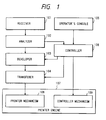
- Fig. 1 is a schematic block diagram showing a function construction of a printing apparatus in the invention and shows a function construction of a laser beam printer shown in Figs. 2 and 3, which will be explained hereinlater, and also shows a function construction of an ink jet printer shown in Fig. 22, which will be explained hereinlater.
- the printing apparatus to which the invention is applied is not limited to the laser beam printer or ink jet printer but can be also applied to a printing apparatus of another printing type.
- reference numeral 101 denotes receiver for receiving input data transmitted from a host computer.
- the input data comprises: print data including data such as character code, graphics, image, or the like which is used to actually perform a printing process, developing position information into a bit map memory, information indicative of a font pattern which is used, and the like; control data for a printing mechanism section (printer engine) 107; and the like.
- the control data denotes, for instance, control data such as to designate switching controls between the feed mode (cassette feed, manual feed) and the delivery mode and between the one-side printing mode and the both-side printing mode or the like and includes setting (front/back direction, right/reverse side, and the like) information of a pre-print sheet.
- the above data can be also expressed by a page describing language (PDL).
- PDL page describing language
- Reference numeral 102 denotes an analyzer for analyzing input data received by the receiver 101 and dividing into the print data and the control data.
- Reference numeral 103 denotes a developer for developing the print data divided by the analyzer 102 as output data into bit map information of at least one page.
- Reference numeral 104 denotes transfer means for transferring the bit map information developed by the developer 103 to a printer mechanism 108 of the printer engine 107.
- Reference numeral 105 denotes an operator's console for displaying a state of the printing apparatus or for designating setting (front/back direction, right/reverse side, and the like) information of a pre-print sheet for the printing apparatus by an operator.
- Reference numeral 106 denotes a controller for judging the setting information of the pre-print sheet set in a cassette on the basis of the control data divided by the analyzer 102 or the setting information of the pre-print sheet designated from the operator's console 105 and for controlling the developer 103, transfer means 104, and a controller mechanism 109 of the printer engine 107.
- the control data can be also expressed by a page describing language (PDL).
- PDL page describing language
- Reference numerals 101 to 106 denote functions in the controller of the printing apparatus.
- Reference numeral 107 denotes the actual printing mechanism section (printer engine); 108 the printer mechanism in the printer engine; and 109 the controller mechanism to control a feed conveying system (paper feed mode and delivering process) or the like in the printer engine.
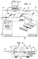
- Figs. 2 and 3 show general constructions in the printing apparatus.
- Reference numeral 201 in Fig. 2 denotes a host computer to transmit various kinds of print data and various kinds of control data to the printing apparatus.
- Reference numeral 202 in Fig. 2 denotes an example of the first printing apparatus to which the invention can be applied (a laser beam printer using a laser beam as a light emitting device is shown here); 203 a controller of the printing apparatus; and 204 a printing mechanism section (printer engine) of the printing apparatus.
- Reference numeral 205 in Fig. 2 denotes a control section to control the electrophotographic process, paper feed conveying system, and optical system and 206 indicates a video interface for receiving an image signal from the controller 203 in Fig. 2, for receiving control commands from the controller, and for transmitting a status of the printer engine to the controller.
- Reference numeral 207 in Fig. 2 denotes an optical system in the printer engine 204 in Fig. 2.
- Reference numeral 208 in Fig. 2 denotes an electrophotographic process or paper feed conveying system in the printer engine 204 in Fig. 2.
- Reference numeral 209 in Fig. 2 denotes an operator's console in the printing apparatus.
- Fig. 3 is a diagram showing the feed conveying system 208 in Fig. 2.
- Reference numeral 301 in Fig. 3 denotes a feed cassette.
- Reference numeral 209 in Fig. 3 denotes the operator's console.
- Reference numeral 303 in Fig. 3 denotes a rotary mirror to irradiate a laser beam onto a photo sensitive drum; 304 a photo sensitive drum; and 305 a fixing device.
- Reference numeral 306 in Fig. 3 denotes a sheet reversing unit in the both-side printing mode and 307 and 308 indicate discharge trays.
- An arrow in the diagram indicates the conveying direction of the sheet in the feed conveying system.
- Fig. 4 shows a block diagram of the controller 203 in Fig. 2.
- reference numeral 401 denotes a central processing unit (CPU) to control the whole controller and 402 indicates a program memory in which a program to control the controller has been stored.
- the program memory 402 is constructed by an ROM (read only memory) and stores various kinds of programs to execute processes in flowcharts shown in Figs. 16, 17, 18 and 19. That is, as shown in Fig. 20, a reception program 2001, an analysis program 2002, a development program 2003, a transfer program 2004, and a control program 2005 are stored in the program memory 402.
- Reference numeral 403 denotes a memory in which font information to develop a character code into a bit map has been stored.
- the memory 403 is constructed by an ROM (read only memory).
- Reference numeral 404 denotes a hardware circuit to transfer the bit map information in which the print data has been developed to an image signal generator 408.
- the hardware circuit 404 is constructed by a DMAC (direct memory access controller) or FIFO.
- Reference numeral 405 denotes a data input interface circuit to connect the host computer 201 and the controller 203.
- the I/F circuit 405 has a memory to temporarily store input data.
- Reference numeral 406 denotes a work memory which is necessary to make the various kinds of programs stored in the program memory 402 operative.
- the work memory 406 is constructed by an RAM (random access memory).
- the work memory 406 also includes a print data storage area 2101, a control data storage area 2102, and a print data development area 2103 of at least one page.
- Reference numeral 407 denotes a data output interface circuit to connect the controller 203 and the printer engine 204; 408 the image signal generator for generating the image signal from the bit map information which has been developed in the print data development area 2103 of at least one page synchronously with the printer engine 204; and 409 a console interface to connect the operator's console 209 and the controller 203.
- Reference numeral 410 denotes an internal bus to connect each of the above memories and each of the above circuits and the CPU 401.
- the flowchart of Fig. 16 shows a flow of the whole printing process.
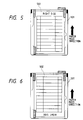
- Figs. 5 and 6 show positional relations between the feed cassette and the pre-print sheet.
- reference numeral 501 denotes a feed cassette and 502 indicates a pre-print sheet.
- Fig. 5 shows a state in which the direction of the pre-print sheet coincides with the feeding direction and such a state will be referred to as a "NORMAL" status hereinbelow.
- Fig. 6 shows a state in which the direction of the pre-print sheet and the feeding direction are opposite and such a state will be referred to as an "ABNORMAL" status hereinafter.
- control data can be also expressed by the page describing language (PDL).
- step S1601 the reception program 2001 discriminates whether the input data has been stored in the input data memory to temporarily store the input data in the data input interface circuit 405 or not. If there is the input data, step S1602 follows. If no input data exists, the processing routine is returned to the first step.
- step S1602 the analysis program 2002 divides the input data into the print data and the control data and respectively stores into the print data storage area 2101 and control data storage area 2102 in the work memory 406.
- step S1603 when the setting information of the pre-print sheet by the operation of the operator's console 209 is supplied through the console interface 409, a check is made in step S1604 to see if the printing apparatus is in the OFF-line mode or the ON-line mode.
- step S1604 When it is determined in step S1604 that the printing apparatus is in the OFF-line mode, the input control data is added and stored into the control data storage area 2102 in the work memory 406 in step S1605.
- step S1604 when it is decided in step S1604 that the printing apparatus is in the ON-line mode, the processing routine is returned to step S1601.
- the hardware can be also constructed so as to always rejecting the console operation in the case where the printing apparatus maintains the ON-line mode by combining the processes in steps S1603 and S1604.
- step S1606 a check is made to see if the printing is started or not on the basis of the paper delivery code in the control data.
- step S1606 When it is decided in step S1606 that the printing is not started yet, the processing routine is returned to step S1601.
- step S1606 when it is determined in step S1606 that the printing is started, developing and printing processes, which will be explained hereinlater, are executed in step S1607.
- step S1608 If all of the input data is not yet developed and printed in step S1608, the processing routine is returned to step S1601. If all of the input data was developed and printed, the processing routine is finished.
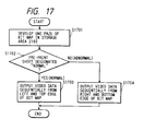
- step S1607 of the flowchart shown in Fig. 16 namely, processes regarding the pre-print sheet and the transferring direction of the image signal in the one-side printing mode will now be described with reference to the flowchart of Fig. 17.
- step S1701 the development program 2003 sequentially develops the bit map of one page into the print data development area 2103 of at least one page in the work memory 406 from the print data stored in the print data storage area 2101 in the work memory 406 by using the font information stored in the font memory 403.
- step S1702 the control program 2005 discriminates whether the pre-print sheet has been designated to the NORMAL status or not on the basis of the control data stored in the control data storage area 2102 in the work memory 406, thereby controlling the transfer program 2004.
- step S1703 follows and the transfer program 2004 sequentially reads out the bit map information from the left and top edge of the developed bit map through the hardware circuit DMAC 404 and data output interface 407 to transfer the bit map information in which the print data has been developed to the image signal generator 408.
- the read-out bit map information is supplied to the printer engine 107 as an image signal and printed.
- step S1704 follows and the transfer program 2004 sequentially reads out the bit map information from the:,right and bottom edge of the developed bit map through the hardware circuit DMAC 404 and data output interface 407 to transfer the bit map information in which the print data has been developed to the image signal generator 408.
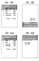
- the read-out bit map information is supplied to the printer engine 107 as an image signal and printed. That is, by sequentially reading out the bit map information as shown by 1302 in Fig. 13 from the developed bit map, the print result as shown by 902 in Fig. 9 is generated to the pre-print sheet as shown by 901 in Fig. 9.
- the developed bit map is set to the same direction as the setting direction of the pre-print sheet and the bit map information is read out.
- the bit map itself is developed in the same direction as the setting direction of the pre-print sheet and the bit map information is always read out from the left and top edge and is generated as an image signal.
- the developing and printing processes can be also executed on the basis of the page describing language (PDL).
- PDL page describing language
- Figs. 5, 6, 7, and 8 show the positional relation between the feed cassette and the pre-print sheet.
- Figs. 5 and 6 are as already described above.
- reference numeral 501 denotes the feed cassette and 502 indicates the pre-print sheet.
- Fig. 7 shows a state in which the pre-print sheet has been set into the same direction as that in Fig. 5 and the sheet has been turned over.
- Fig. 8 shows a state in which the pre-print sheet has been set into the same direction as that in Fig. 6 and the sheet has been turned over.
- control data can be also expressed by the page describing language (PDL).
- step S1801 the control program 2005 discriminates whether the pre-print sheet has been designated to the right side or not on the basis of the control data stored in the control data storage area 2102 in the work memory 406, thereby controlling the development program 2003.
- step S1802 follows and the development program 2003 sequentially develops the bit map for the right side page into the print data development area 2103 in the work memory 406 from the print data stored in the print data storage area 2101 in the work memory 406 by using the font information stored in the font memory 403.
- step S1803 follows and the development program 2003 sequentially develops the bit map for the reverse side page into the print data development area 2103 in the work memory 406 from the print data stored in the print data storage area 2101 in the work memory 406 by using the font information stored in the font memory 403.
- step S1804 the control program 2005 designates a tray to the sheet reversing unit.
- step S1805 the control program 2005 checks whether the pre-print sheet has been designated to the "NORMAL" status or not on the basis of the control data stored in the control data storage area 2102 in the work memory 406, thereby controlling the transfer program 2004.
- step S1806 follows and the transfer program 2004 sequentially reads out the bit map information from the left and top edge of the developed bit map through the hardware circuit DMAC 404 and the data output interface 407 to transfer the bit map information in which the print data has been developed to the image signal generator 408.
- the read-out bit map information is supplied to the printer engine 107 as an image signal and printed.
- step S1807 follows and the transfer program 2004 sequentially reads out the bit map information from the right and bottom edge of the developed bit map through the hardware circuit DMAC 404 and the data output interface 407 to transfer the bit map information in which the print data has been developed to the image signal generator 408.
- the readout bit map information is supplied to the printer engine 107 as an image signal and printed.
- the developed bit map is set to the same direction as the setting direction of the pre-print sheet and the bit map information is read out.
- the bit map information is read out.
- the above developing and printing processes can be also executed on the basis of the page describing language (PDL).
- PDL page describing language
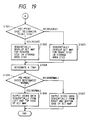
- step S1901 the control program 2005 checks whether the pre-print sheet has been designated to the right side or not on the basis of the control data stored in the control data storage area 2102 in the work memory 406, thereby controlling the development program 2003.
- step S1902 follows and the development program 2003 sequentially develops the bit map for the reverse side page into the print data development area 2103 in the work memory 406 from the print data stored in the print data storage area 2101 in the work memory 406 by using the font information stored in the font memory 403.
- step S1903 follows and the development program 2003 sequentially develops the bit map for the right side page into the print data development area 2103 in the work memory 407 from the print data stored in the print data storage area 2101 in the work memory 406 by using the font information stored in the font memory 403.
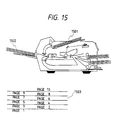
- step S1904 the control program 2005 designates a tray.
- a tray indicated by 1501 in Fig. 15 is designated.
- a tray shown by 1502 in Fig. 15 is designated.
- step S1905 the control program 2005 discriminates whether the pre-print sheet has been designated to the NORMAL status or not on the basis of the control data stored in the control data storage area 2102 in the work memory 406, thereby controlling the transfer program 2004.
- step S1906 follows and the transfer program 2004 sequentially reads out the bit map information from the left-and top edge of the developed bit map through the hardware circuit DMAC 404 and the data output interface 407 to transfer the bit map information in which the print data has been developed to the image signal generator 408.
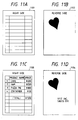
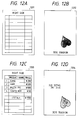
- the read-out bit map information is supplied to the pirnter engine 107 as an image signal and printed. That is, as shown in 1301 in Fig. 13, by sequentially reading out the bit map information from the developed bit map, the correct print result as shown by 1104 in Fig. 11 is generated to the pre-print sheet as shown by 1102 in Fig. 11.
- step S1907 follows and the transfer program 2004 sequentially reads out the bit map information from the right and bottom edge of the developed bit map through the hardware circuit DMAC 404 and the data output interface 407 to transfer the bit map information in which the print data has been developed to the image signal generator 408.
- the read-out bit map information is supplied to the printer engine 107 as an image signal and printed.
- the developed bit map is set to the same direction as the setting direction of the pre-print sheet and the bit map information is read out.
- the bit map itself is developed in the same direction as the setting direction of the pre-print sheet and the bit map information is always read out from the left and top edge and is generated as an image signal.
- the above developing and printing processes can be also executed on the basis of the page describing language (PDL).
- PDL page describing language
- the laser beam printer using the electrophotographic process has been assumed as a printer mechanism to which the invention can be applied.
- the invention can be also applied to an ink jet printer as shown in Fig. 22 so long as it is page printer for performing the printing process on a page unit basis irrespective of the kind of printer mechanism.
- the printing apparatus to which the invention is applied is not limited to the above laser beam printer or ink jet printer but the invention can be also obviously applied to printing apparatuses of the other printing systems.
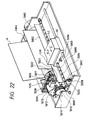
- Fig. 22 is an external view showing a structure of a second printing apparatus to which the invention can be applied and shows the case of, for instance, an ink jet printing apparatus (IJRA).
- IJRA ink jet printing apparatus
- a lead screw 5005 rotates through driving force transfer gears 5011 and 5009 interlockingly with the forward/reverse rotation of a driving motor 5013.
- a carriage HC is come into engagement with a spiral groove 5004 of the lead screw 5005.
- the carriage HC has a pin (not shown) and is reciprocatingly moved in the directions shown by arrows a and b.
- An ink jet cartridge IJC is mounted to the carriage HC.
- Reference numeral 5002 denotes a paper pressing plate to press a paper onto a platen 5000 in the moving direction of the carriage.
- Reference numerals 5007 and 5008 denote photo couplers each of which functions as home position detecting means for detecting the existence of a lever 5006 of the carriage in the region corresponding to the photo coupler and for performing the switching of the rotating direction of the motor 5013 or the like.
- Reference numeral 5016 denotes a member to indicate a cap member 5022 to cap the whole surface of a recording head; 5015 sucking means for sucking the inside of the cap and for performing a sucking recovery of the recording head through an opening 5023 in the cap; 5017 a cleaning blade which can be moved in the front/back directions by a member 5019; 5018 a main body supporting plate to support the cleaning blade 5017 and member 5019; and 5012 a lever to start the sucking of the sucking recovery.
- the lever 5012 is moved in association with the movement of a cam 5020 which is come into engagement with the carriage.
- the driving force from the driving motor is transferred and controlled by well-known transfer means such as clutch switching means or the like.
- the capping, cleaning, and sucking recovery are constructed in a manner such that a desired process can be executed at the corresponding position by the operation of the lead screw 5005 when the carriage reaches the hold position side region. However, it is sufficient to execute a desired operation at a well-known timing.
- the setting (front/back direction, right/reverse, and the like) of the pre-print sheet can be designated by a command which is transmitted from the host computer or by a console operation, the correct print result can be always obtained irrespective of the limitation of the printer mechanism, difference of the printing processes between the one-side printing mode and the both-side printing mode, and the like.
- the invention can be applied to a system comprising a plurality of equipment or an apparatus comprising one equipment.
- the invention can be also obviously applied to the case where the invention is accomplished by supplying a program to embody the invention to such a system or apparatus.
Landscapes
- Engineering & Computer Science (AREA)
- General Engineering & Computer Science (AREA)
- Physics & Mathematics (AREA)
- General Physics & Mathematics (AREA)
- Theoretical Computer Science (AREA)
- Record Information Processing For Printing (AREA)
- Accessory Devices And Overall Control Thereof (AREA)
Claims (14)
- Appareil d'impression capable d'imprimer recto verso sur une feuille d'impression et constitué d'un moyen de développement (163, 401) pour transformer des données d'impression reçues en information en mode point, données d'impression qui incluent des données pour imprimer recto verso sur une même feuille d'enregistrement et une mémoire de développement (406) pour stocker les données de points développées à imprimer sur la feuille d'impression et caractérisé en ce que l'appareil comprend, en outre, un moyen d'entrée (209, 405) grâce auquel une première et une seconde informations de désignation peuvent être introduites dans l'appareil, la première information de désignation désignant une orientation normale ou anormale de la feuille d'impression par rapport au sens d'alimentation et la seconde information de désignation désignant une orientation correcte ou inversée de la face de la feuille d'impression par rapport à l'unité d'impression ;un premier moyen de détermination (106, S1805, S1905) conçu pour déterminer, en fonction de la première information de désignation, le sens dans lequel des données d'impression reçues doivent être imprimées sur une feuille d'impression,un second moyen de détermination (106, S1801, S1901) conçu pour déterminer, en fonction de la seconde information de désignation, sur quelle face d'une feuille d'impression les données de points développées doivent être imprimées en premier ; etun moyen de commande (106, S1806, S1807, S1906, S1907) conçu pour commander le sens de développement des données d'impression dans la mémoire de développement ou le sens de lecture de données de points développées à partir de la mémoire de développement (406) en réponse à une sortie dudit premier moyen de détermination et pour commander le développement des données d'impression reçues, afin que des données de points concernant une des deux faces d'une feuille d'enregistrement soient développées avant les données de points de l'autre face d'après la sortie dudit second moyen de détermination.
- Appareil selon la revendication 1, dans lequel les données d'impression incluent un code de caractère, une information de position pour développer le code de caractère dans la mémoire de développement et une information donnant un profil de police utilisé au cours du développement.
- Appareil selon l'une ou l'autre des revendications précédentes, dans lequel ladite mémoire de développement a une capacité d'une page au moins.
- Appareil selon l'une quelconque des revendications précédentes, dans lequel lesdites première et seconde informations de désignation sont fixées par un ordinateur hôte.
- Appareil selon l'une quelconque des revendications précédentes, dans lequel lesdites première et seconde informations de désignation peuvent être entrées dans ledit moyen d'entrée à partir d'une console d'opérateur (209).
- Appareil selon la revendication 4 et la revendication 5 dans lequel, lorsque ledit moyen de commande contrôle l'ordre dans lequel est développée l'information de points par le moyen de développement, la préférence est donnée à l'information fixée par un ordinateur hôte.
- Appareil selon l'une quelconque des revendications précédentes, dans lequel ledit moyen de développement développe les données d'impression reçues dans la mémoire de développement en fonction d'un langage de description de page.
- Appareil selon l'une quelconque des revendications précédentes, dans lequel lesdites première et seconde informations de désignation sont incluses dans un langage de description de page.
- Procédé d'impression recto verso sur une feuille d'impression consistant à transformer (163, 401) les données d'impression reçues en information en mode point, données d'impression qui incluent des données pour imprimer sur les deux faces d'une même feuille d'enregistrement, à stocker les données de points développées dans une mémoire de développement (406), à imprimer les données de points développées et caractérisé par l'introduction d'une première et d'une seconde informations de désignation, la première information de désignation désignant une orientation normale ou anormale de la feuille d'impression par rapport au sens d'alimentation et la seconde information de désignation désignant une orientation correcte ou inversée du recto de la feuille d'impression par rapport à l'unité d'impression ;à utiliser un premier moyen de détermination (106, S1805, S1905) en réponse à la première information de désignation pour déterminer le sens dans lequel des données d'impression reçues doivent être imprimées sur une feuille d'impression,à utiliser un second moyen de détermination (106, S1801, S1901) en réponse à la seconde information de désignation pour déterminer sur quelle face d'une feuille d'impression les données de points développées doivent être imprimées en premier ; età utiliser un moyen de commande (106, S1806, S1807, S1906, S1907) pour commander le sens de développement des données d'impression dans la mémoire de développement ou le sens de lecture de données de points développées à partir de ladite mémoire de développement (406) en réponse à une sortie dudit premier moyen de détermination et pour commander le développement des données d'impression reçues pour que des données de points concernant une des deux faces d'une feuille d'enregistrement soient développées avant les données de points de l'autre face, d'après la sortie dudit second moyen de détermination.
- Procédé selon la revendication 9, dans lequel les données d'impression incluent un code de caractère, une information de position pour développer le code de caractère dans la mémoire de développement et une information donnant un profil de police de caractères utilisé au cours du développement.
- Procédé selon la revendication 9 ou la revendication 10, dans lequel lesdites première et seconde informations de désignation sont fixées par un ordinateur hôte.
- Procédé selon la revendication 11, dans lequel l'ordre dans lequel les informations de points sont développées par le moyen de développement est commandé, de préférence, par l'information fournie par un ordinateur hôte.
- Procédé selon l'une quelconque des revendications 9 à 12, dans lequel ledit moyen de développement développe les données d'impression reçues dans la mémoire de développement en fonction d'un langage de description de page.
- Procédé selon l'une quelconque des revendications 9 à 13, dans lequel lesdites première et seconde informations de désignation sont incluses dans un langage de description de page.
Applications Claiming Priority (2)
| Application Number | Priority Date | Filing Date | Title |
|---|---|---|---|
| JP3323052A JP2821296B2 (ja) | 1991-12-06 | 1991-12-06 | 印刷方法及び装置 |
| JP323052/91 | 1991-12-06 |
Publications (2)
| Publication Number | Publication Date |
|---|---|
| EP0545732A1 EP0545732A1 (fr) | 1993-06-09 |
| EP0545732B1 true EP0545732B1 (fr) | 1998-04-22 |
Family
ID=18150567
Family Applications (1)
| Application Number | Title | Priority Date | Filing Date |
|---|---|---|---|
| EP92311104A Expired - Lifetime EP0545732B1 (fr) | 1991-12-06 | 1992-12-04 | Dispositif pour imprimer des données binaires organisées en pages |
Country Status (4)
| Country | Link |
|---|---|
| US (1) | US5768485A (fr) |
| EP (1) | EP0545732B1 (fr) |
| JP (1) | JP2821296B2 (fr) |
| DE (1) | DE69225200T2 (fr) |
Families Citing this family (7)
| Publication number | Priority date | Publication date | Assignee | Title |
|---|---|---|---|---|
| JP3689502B2 (ja) * | 1996-10-04 | 2005-08-31 | キヤノン株式会社 | 印刷制御装置および印刷制御方法 |
| JP2000177196A (ja) * | 1998-12-15 | 2000-06-27 | Seiko Epson Corp | プリンタ装置、印字方法および記録媒体 |
| US7262873B1 (en) | 2000-07-05 | 2007-08-28 | Lexmark International, Inc. | Photoprinter access to remote data |
| JP3520500B2 (ja) * | 2000-07-26 | 2004-04-19 | セイコーエプソン株式会社 | プリンタ、プリンタの制御方法、そのためのプログラム、及び、そのプログラムを記録した記録媒体 |
| US7061630B2 (en) * | 2000-12-15 | 2006-06-13 | Xerox Corporation | System architecture and method for verifying process correctness in a document processing system |
| GB2412264A (en) * | 2004-03-20 | 2005-09-21 | Hewlett Packard Development Co | Improvements in and relating to multiple printing passes |
| JP5371640B2 (ja) | 2009-09-03 | 2013-12-18 | キヤノン株式会社 | 画像形成装置、制御方法、プログラム |
Family Cites Families (13)
| Publication number | Priority date | Publication date | Assignee | Title |
|---|---|---|---|---|
| JPS61225075A (ja) * | 1985-03-30 | 1986-10-06 | Toshiba Corp | 印字装置 |
| JPH0673972B2 (ja) * | 1987-01-24 | 1994-09-21 | 株式会社日立製作所 | レ−ザプリンタ制御装置 |
| JPH085213B2 (ja) * | 1987-03-04 | 1996-01-24 | ブラザー工業株式会社 | 印字装置 |
| JPH01196675A (ja) * | 1988-01-30 | 1989-08-08 | Toshiba Corp | パターンデータ生成方式 |
| US4992957A (en) * | 1988-03-17 | 1991-02-12 | Seiko Epson Corporation | Printer and method for utilizing character codes and control codes within a printer |
| US5220645A (en) * | 1989-03-07 | 1993-06-15 | Canon Kabushiki Kaisha | Output apparatus |
| JP2647534B2 (ja) * | 1990-04-12 | 1997-08-27 | キヤノン株式会社 | 出力装置 |
| JPH0468638A (ja) * | 1990-07-04 | 1992-03-04 | Ricoh Co Ltd | 文書処理装置 |
| US5293466A (en) * | 1990-08-03 | 1994-03-08 | Qms, Inc. | Method and apparatus for selecting interpreter for printer command language based upon sample of print job transmitted to printer |
| US5165014A (en) * | 1990-09-12 | 1992-11-17 | Hewlett-Packard Company | Method and system for matching the software command language of a computer with the printer language of a printer |
| DE4139488A1 (de) * | 1990-11-30 | 1992-08-13 | Kanzaki Paper Mfg Co Ltd | Drucker |
| JP2661416B2 (ja) * | 1991-06-29 | 1997-10-08 | ブラザー工業株式会社 | 印字システム |
| US5222200A (en) * | 1992-01-08 | 1993-06-22 | Lexmark International, Inc. | Automatic printer data stream language determination |
-
1991
- 1991-12-06 JP JP3323052A patent/JP2821296B2/ja not_active Expired - Fee Related
-
1992
- 1992-12-03 US US07/984,840 patent/US5768485A/en not_active Expired - Lifetime
- 1992-12-04 DE DE69225200T patent/DE69225200T2/de not_active Expired - Fee Related
- 1992-12-04 EP EP92311104A patent/EP0545732B1/fr not_active Expired - Lifetime
Also Published As
| Publication number | Publication date |
|---|---|
| JP2821296B2 (ja) | 1998-11-05 |
| DE69225200D1 (de) | 1998-05-28 |
| DE69225200T2 (de) | 1998-08-27 |
| US5768485A (en) | 1998-06-16 |
| JPH05155071A (ja) | 1993-06-22 |
| EP0545732A1 (fr) | 1993-06-09 |
Similar Documents
| Publication | Publication Date | Title |
|---|---|---|
| US6606466B2 (en) | Print control apparatus indicating appropriate paper cassette for printing and method of same | |
| US6055361A (en) | Printer control with monitor function | |
| US20020048034A1 (en) | Printer apparatus, printer system and control method therefor | |
| EP0834828B1 (fr) | Imprimante hybride équipée de plusieurs mécanismes d'impression, et sa méthode de contrôle | |
| US5678000A (en) | Printer control apparatus | |
| US6353484B2 (en) | Output control apparatus and method and storage medium storing computer readable program | |
| EP0550158B1 (fr) | Appareil d'impression et procédé de contrÔle d'impression | |
| EP0573983B1 (fr) | Appareil de traitement de données et appareil de sortie de données | |
| EP0545732B1 (fr) | Dispositif pour imprimer des données binaires organisées en pages | |
| US6099181A (en) | Printing control apparatus, printing method with the printing control apparatus, and storage medium storing a computer readable program | |
| US6903832B2 (en) | Output control apparatus, output control method and memory medium storing program readable by computer | |
| US5758041A (en) | Output control method and apparatus | |
| EP0902357B1 (fr) | Procédé de sortie et dispositif | |
| EP0802502B1 (fr) | Contrôle de formation d'image basé sur le changement de l'état des moyens de formation d'image | |
| EP0651317B1 (fr) | Méthode et appareil de sortie pour estimer la qualité d'image avant de sortir | |
| EP0583891B1 (fr) | Dispositif et méthode de sortie | |
| US5889930A (en) | Output method and apparatus | |
| US6192208B1 (en) | Printing apparatus, control method for the same, and computer-readable storage medium storing printing-apparatus control program | |
| JPH11115280A (ja) | プリンタ | |
| JPH079703A (ja) | 印刷装置 | |
| US6397265B1 (en) | Print control apparatus for communicating with a selected external apparatus to control a printer | |
| JPH07302178A (ja) | 印刷装置およびその制御方法 | |
| JP3195097B2 (ja) | 出力制御方法および装置 | |
| JP2871981B2 (ja) | 印刷装置及びその制御方法 | |
| JP3281465B2 (ja) | 印刷装置及びその制御方法及びその状態表示方法 |
Legal Events
| Date | Code | Title | Description |
|---|---|---|---|
| PUAI | Public reference made under article 153(3) epc to a published international application that has entered the european phase |
Free format text: ORIGINAL CODE: 0009012 |
|
| AK | Designated contracting states |
Kind code of ref document: A1 Designated state(s): DE FR GB IT |
|
| 17P | Request for examination filed |
Effective date: 19931022 |
|
| 17Q | First examination report despatched |
Effective date: 19960404 |
|
| GRAG | Despatch of communication of intention to grant |
Free format text: ORIGINAL CODE: EPIDOS AGRA |
|
| GRAG | Despatch of communication of intention to grant |
Free format text: ORIGINAL CODE: EPIDOS AGRA |
|
| GRAH | Despatch of communication of intention to grant a patent |
Free format text: ORIGINAL CODE: EPIDOS IGRA |
|
| GRAH | Despatch of communication of intention to grant a patent |
Free format text: ORIGINAL CODE: EPIDOS IGRA |
|
| GRAA | (expected) grant |
Free format text: ORIGINAL CODE: 0009210 |
|
| AK | Designated contracting states |
Kind code of ref document: B1 Designated state(s): DE FR GB IT |
|
| ITF | It: translation for a ep patent filed | ||
| REF | Corresponds to: |
Ref document number: 69225200 Country of ref document: DE Date of ref document: 19980528 |
|
| ET | Fr: translation filed | ||
| PLBE | No opposition filed within time limit |
Free format text: ORIGINAL CODE: 0009261 |
|
| 26N | No opposition filed | ||
| REG | Reference to a national code |
Ref country code: GB Ref legal event code: IF02 |
|
| PGFP | Annual fee paid to national office [announced via postgrant information from national office to epo] |
Ref country code: GB Payment date: 20041122 Year of fee payment: 13 |
|
| PGFP | Annual fee paid to national office [announced via postgrant information from national office to epo] |
Ref country code: FR Payment date: 20041220 Year of fee payment: 13 |
|
| PGFP | Annual fee paid to national office [announced via postgrant information from national office to epo] |
Ref country code: DE Payment date: 20050217 Year of fee payment: 13 |
|
| PG25 | Lapsed in a contracting state [announced via postgrant information from national office to epo] |
Ref country code: IT Free format text: LAPSE BECAUSE OF NON-PAYMENT OF DUE FEES Effective date: 20051204 Ref country code: GB Free format text: LAPSE BECAUSE OF NON-PAYMENT OF DUE FEES Effective date: 20051204 |
|
| PG25 | Lapsed in a contracting state [announced via postgrant information from national office to epo] |
Ref country code: DE Free format text: LAPSE BECAUSE OF NON-PAYMENT OF DUE FEES Effective date: 20060701 |
|
| GBPC | Gb: european patent ceased through non-payment of renewal fee |
Effective date: 20051204 |
|
| PG25 | Lapsed in a contracting state [announced via postgrant information from national office to epo] |
Ref country code: FR Free format text: LAPSE BECAUSE OF NON-PAYMENT OF DUE FEES Effective date: 20060831 |
|
| REG | Reference to a national code |
Ref country code: FR Ref legal event code: ST Effective date: 20060831 |