EP0834855A1 - Verfahren und vorrichtung für rollende bildschirmanzeige - Google Patents
Verfahren und vorrichtung für rollende bildschirmanzeige Download PDFInfo
- Publication number
- EP0834855A1 EP0834855A1 EP97917405A EP97917405A EP0834855A1 EP 0834855 A1 EP0834855 A1 EP 0834855A1 EP 97917405 A EP97917405 A EP 97917405A EP 97917405 A EP97917405 A EP 97917405A EP 0834855 A1 EP0834855 A1 EP 0834855A1
- Authority
- EP
- European Patent Office
- Prior art keywords
- bar
- shaped display
- display elements
- image data
- dots
- Prior art date
- Legal status (The legal status is an assumption and is not a legal conclusion. Google has not performed a legal analysis and makes no representation as to the accuracy of the status listed.)
- Granted
Links
Images


Classifications
-
- G—PHYSICS
- G09—EDUCATION; CRYPTOGRAPHY; DISPLAY; ADVERTISING; SEALS
- G09G—ARRANGEMENTS OR CIRCUITS FOR CONTROL OF INDICATING DEVICES USING STATIC MEANS TO PRESENT VARIABLE INFORMATION
- G09G3/00—Control arrangements or circuits, of interest only in connection with visual indicators other than cathode-ray tubes
- G09G3/20—Control arrangements or circuits, of interest only in connection with visual indicators other than cathode-ray tubes for presentation of an assembly of a number of characters, e.g. a page, by composing the assembly by combination of individual elements arranged in a matrix no fixed position being assigned to or needed to be assigned to the individual characters or partial characters
-
- G—PHYSICS
- G09—EDUCATION; CRYPTOGRAPHY; DISPLAY; ADVERTISING; SEALS
- G09G—ARRANGEMENTS OR CIRCUITS FOR CONTROL OF INDICATING DEVICES USING STATIC MEANS TO PRESENT VARIABLE INFORMATION
- G09G3/00—Control arrangements or circuits, of interest only in connection with visual indicators other than cathode-ray tubes
- G09G3/004—Control arrangements or circuits, of interest only in connection with visual indicators other than cathode-ray tubes to give the appearance of moving signs
-
- G—PHYSICS
- G09—EDUCATION; CRYPTOGRAPHY; DISPLAY; ADVERTISING; SEALS
- G09G—ARRANGEMENTS OR CIRCUITS FOR CONTROL OF INDICATING DEVICES USING STATIC MEANS TO PRESENT VARIABLE INFORMATION
- G09G3/00—Control arrangements or circuits, of interest only in connection with visual indicators other than cathode-ray tubes
- G09G3/20—Control arrangements or circuits, of interest only in connection with visual indicators other than cathode-ray tubes for presentation of an assembly of a number of characters, e.g. a page, by composing the assembly by combination of individual elements arranged in a matrix no fixed position being assigned to or needed to be assigned to the individual characters or partial characters
- G09G3/22—Control arrangements or circuits, of interest only in connection with visual indicators other than cathode-ray tubes for presentation of an assembly of a number of characters, e.g. a page, by composing the assembly by combination of individual elements arranged in a matrix no fixed position being assigned to or needed to be assigned to the individual characters or partial characters using controlled light sources
- G09G3/30—Control arrangements or circuits, of interest only in connection with visual indicators other than cathode-ray tubes for presentation of an assembly of a number of characters, e.g. a page, by composing the assembly by combination of individual elements arranged in a matrix no fixed position being assigned to or needed to be assigned to the individual characters or partial characters using controlled light sources using electroluminescent panels
- G09G3/32—Control arrangements or circuits, of interest only in connection with visual indicators other than cathode-ray tubes for presentation of an assembly of a number of characters, e.g. a page, by composing the assembly by combination of individual elements arranged in a matrix no fixed position being assigned to or needed to be assigned to the individual characters or partial characters using controlled light sources using electroluminescent panels semiconductive, e.g. using light-emitting diodes [LED]
Definitions
- This invention relates to a method of and an apparatus for scrolling displaying characters or a graphic form on a light emitting cell array wherein light emitting cells such as high luminance LEDs (light emitting diodes) are arranged two-dimensionally.
- light emitting cells such as high luminance LEDs (light emitting diodes) are arranged two-dimensionally.
- a character train is scrolling displayed on a display panel of a limited size.
- character train data of the bit map type wherein one character is composed of 16 x 16 dots are successively produced and displayed by scrolling on a display panel of the dot matrix type wherein sixteen (16) dots are arranged in a column and a number of dots greater than at least several times as large as sixteen (16) are arranged in a row.
- the size of a display panel is increased by increasing the number of light emitting cells without increasing the distances between the light emitting cells very much.
- the definition of display data is increased by constructing one character with 32 x 32 dots or the like.
- a large number of light emitting cells are mounted on a circuit board and accommodated in a flat panel type case together with a drive circuit.
- the display panel has a rigid body and is not so flexible as to allow it to be folded freely (although it may be divided into several parts), divided into small parts or contracted or expanded. While a display panel of a very small size can be carried entirely (some display panels for advertisement of a store are portable), most of display panels of the type described are installed fixedly at predetermined locations. This apparatus form is considered to be one of obstacles to expansion in application.
- the present invention has been made in view of the conventional problems described above, and particularly, in order to attain the following and other objects:
- the scrolling display method and apparatus of the present invention includes the following features:
- the scrolling display apparatus comprises data distribution means for specifying image data for w columns of one frame to be displayed subsequently from among entire image data produced in the form of a bit map and stored in a memory in accordance with a frame address and for selecting image data for n columns at intervals from the image data for w columns of one frame and distributing the selected image data to the bar-shaped display elements, light emission driving means for controlling and driving the m light emitting cells of each of the bar-shaped display elements in accordance with the image data of m dots for one column received from the data distribution means at a predetermined timing, and frame shifting means for successively updating the frame address to successively shift the frame to be specified from within the entire image data in a scrolling direction.
- the data distribution means includes means for storing a standard value set corresponding to a standard arrangement distance of the bar-shaped display elements as the interval control variable, and means for storing a correction value set for a particular one of the bar-shaped display elements which is arranged in a displaced condition from the standard arrangement distance, and the data distribution means selectively extracts image data for one column to be distributed to each of the bar-shaped display elements based on the standard value and the correction value.
- the scrolling display apparatus comprises, as a man-machine interface, means for arbitrarily setting and inputting the standard value, and means for setting and inputting the correction value in a corresponding relationship to an identifier of a pertaining one of the bar-shaped display elements.
- the data distribution means includes means for storing, as the interval control variable, position data set proportionally corresponding to the arrangement position of each of the bar-shaped display elements from an origin, and selectively extracts image data for one column to be distributed to each of the bar-shaped display elements based on the position data.
- the scrolling display apparatus comprises, as a man-machine interface, means for setting and inputting the position data in a corresponding relationship to an identifier of each of the bar-shaped display elements.
- the data distribution means includes means for storing, as the interval control variable, distance data set proportionally corresponding to the distance of each of the bar-shaped display elements from an adjacent one of the bar-shaped display elements, and selectively extracts image data for one column to be distributed to each of the bar-shaped display elements based on the distance data.
- the scrolling display apparatus comprises, as a man-machine interface, means for setting and inputting the distance data in a corresponding relationship to an identifier of each of the bar-shaped display elements.
- the arrangement distances of the ten (10) bar-shaped display elements B1 to B10 are sufficiently rough, and an average distance of the same is approximately six times as large as the distance between the light emitting cells C of one of the bar-shaped display elements Bi .
- w is 5.5 times as large as n.
- the ten (10) bar-shaped display elements B1 to B10 which compose the physical screen described above are distributed and arranged substantially uniformly in average in the imaginary screen.
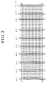
- bit map screen data wherein one column includes sixteen (16) dots and one row includes fifty five (55) dots (an image of a character train of "AVIX"), are expanded on the imaginary screen to display the data as seen in FIG.3 , actually those image data for ten (10) columns selected at intervals from among the image data for fifty five (55) columns are distributed to the ten (10) bar-shaped display elements B1 to B10 and the sixteen (16) light emitting cells C of each of the bar-shaped display elements Bi are controlled in accordance with data of sixteen (16) dots for each column.
- the column distances in selection at intervals depend upon an interval control variable which can be set arbitrarily in accordance with the arrangement distances of the bar-shaped display elements B1 to B10 distributed and arranged on the imaginary screen.
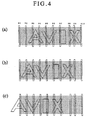
- bit map image data to be expanded on the imaginary screen are successively shifted in a direction of a row, data processing for controlling and driving the light emitting cells C of the bar-shaped display elements B1 to B10 in accordance with image data selected at intervals in such a manner as described above is repeated so that, for example, as seen in FIG. 4 , a scrolling image of a dot density wherein one column includes sixteen (16) dots and one row includes fifty five (55) dots may be visually observed by an after-image effect of a person who watches the imaginary screen.
- each of the bar-shaped display elements Bi wherein sixteen (16) light emitting cells C are arranged linearly has a drive circuit DSi of sixteen (16) bits provided therefor.
- the drive circuit DSi includes a shift register 6 of sixteen (16) bits, a latch circuit 7 of sixteen (16) bits and a driver 8 of sixteen (16) bits formed as a unitary member.
- Image data of the bit map type of a size wherein one column includes sixteen (16) bits and one row has a free length are stored in an image memory 3 of a central control unit 2 .
- image data data of sixteen (16) bits of each column is referred to as column data, and the individual column data are successively numbered as D1 , D2 , D3 , ... (a general term is represented as Dj ).
- Dj a general term is represented as .
- the image memory 3 has a construction of sixteen (16) bits for one word, and column data Dj is stored in an address j .
- a processor 4 of the central control unit 2 read accesses the image memory 3 in the following manner.
- Column data Dj of sixteen (16) bits read out parallel from the image memory 3 are converted into serial data by a parallel/serial conversion shift register 5 and inputted to the (16 x 10) bit shift register wherein the n 16-bit shift register 6 are connected in series as described above.
- column data for ten (10) columns in series from the central control unit 2 is converted into serial data by a parallel/serial conversion shift register 5 and inputted to the (16 x 10) bit shift register wherein the n 16-bit shift register 6 are connected in series as described above.
- a latch signal is provided from the central control unit 2 to the drive circuits DSi to transfer the data of the shift registers 6 to the latch circuits 7 , and the light emitting cells C are driven with the data by the driver 8 . Simultaneously, the data of the shift registers 6 are updated. Scrolling displaying is performed by repeating the operations described above.
- FIG. 2 which illustrates the relationship between the physical screen and the imaginary screen described above, except the eighth (8th) bar-shaped display element B8 , all of the other bar-shaped display units are arranged at intervals of six (6) dots on the imaginary screen.
- the particular bar-shaped display element B8 is arranged at a location displaced by two (2) dots rightwardly from the standard arrangement position at the 6-bit distance.
- the distance between the bar-shaped display elements B8 and B19 is larger by two (2) dots than the standard value "6" and corresponds to eight (8) bits.
- the distance between the bar-shaped display elements B8 and B21 is smaller by two (2) dots than the standard value "6" and corresponds to four (4) dots.
- They are the set contents of "standard value: 6" and "correction value: B8 +2" regarding the interval control variable described hereinabove.
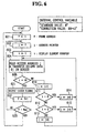
- a control procedure as the data distribution means by the processor 4 is illustrated in a flow chart of FIG. 6 . It is assumed that, in this operation example, the contents mentioned above are set as the interval control variable.
- the image memory 3 is read accessed with the address j indicated by the address pointer j , and column data Dj thus read out is transferred in series in such a manner as described hereinabove. In the description till now, the column data D1 is transferred in series.
- step 613 in which six (6) is added to the value of the address pointer j .
- the added value six (6) is the value prescribed by the "standard value: 6" of the interval control variable.
- step 604 in which the image memory 3 is read accessed with the address j which has increased by six (6) and column data Dj thus read out is transferred in series. In the description till now, column data D7 is transferred in series.
- step 621 column data for ten (10) columns are outputted in order of D1 -> D7 -> D13 -> D19 -> D25 -> D31 -> D37 -> D45 -> D49 -> D55 , and they are latched by the latch circuits 7 of the ten (10) bar-shaped display elements B1 to B10 and displayed simultaneously.
- the ten (10) bar-shaped display elements B1 to B10 are driven to display in the following relationship:
- next step 622 the value of the frame address f is incremented by one.
- next step 623 it is checked whether or not the incremented value of f is a final value Max .
- image data for fifty five (55) columns of one frame to be displayed subsequently are specified in accordance with the frame address f , and image data for ten (10) columns are selected at intervals from the image data for fifty five (55) columns of one frame and distributed to the ten (10) bar-shaped display elements B1 to B10 .
- the sixteen (16) light emitting cells C are controlled and driven at a predetermined timing in accordance with the image data Di of sixteen (16) bits for one column distributed thereto.
- the frame address f is successively updated so that the frame to be specified from within the entire image data is successively shifted in the scrolling direction.
- a scrolling image of a density wherein one column includes sixteen (16) bits and one row includes fifty five (55) dots is visually observed by an after-image effect of a person who watches the imaginary screen.
- step 623 If the frame address f becomes equal to the final value Max as a result of scrolling of the image, then the processing returns from step 623 to first step 601, in which the frame address f is initialized to one (1) to thereafter repeat the processing described above. It is to be noted that, if a series of images are scrolling displayed once or a plurality of times, then different images can be scrolling displayed successively by a different process in which the bit map data of a display object area of the image memory 3 are rewritten or the display object area is switched to another storage area for bit map data of another image.
- FIG.7 An example wherein the manner of arrangement of the bar-shaped display elements B1 to B10 of FIG.2 is modified a little is shown in FIG.7 .
- the bar-shaped display elements B1 to B7 are arranged at intervals of six (6) dots, and an 8-bit distance is provided between the bar-shaped display elements B7 and B8 .
- This is same as that in FIG.2 , and what is different is that a standard six (6) dot distance is provided between the bar-shaped display elements B8 and B9 .
- a six (6) dot distance is provided between the bar-shaped display elements B9 and B10 .
- the setting method may be prescribed such that the distance between the bar-shaped display element B8 and the succeeding bar-shaped display element B9 may be returned to the standard six (6) bit distance.
- the dot construction of the imaginary screen described above exhibits an increase of two (2) columns and includes 16 dots x 57 dots.
- the algorithm for data distribution control must be modified a little from that of FIG.6 .
- the processing in step 612 and step 615 is omitted, and column data later by six (6) columns than column data distributed for B8 is distributed for B9 .
- the method of determination of the interval control variable and the algorithm for data distribution control such that they match each other, when it is tried to install a large number of bar-shaped display elements at a site in any of various situations to work the present invention, even if the distances between the bar-shaped display elements are not necessarily be fixed, an image of a correct aspect ratio over the entire screen can be displayed without distorting the displayed image.
- the central control unit 2 which serves as the center of the present system can be realized by adding required hardware and software to an ordinary personal computer. Since an ordinary personal computer includes a keyboard and a display unit, a man-machine interface for arbitrarily setting the interval control variable may be implemented making use of this. In short, a system may be constructed such that a setting screen for the interval control variable is displayed on the display unit and a suitable numerical value is written in the screen by inputting from the keyboard.
- the central control unit 2 is constructed as an exclusive machine in such a form that it does not have an advanced man-machine interface resource such as a keyboard or a display unit of a personal computer.
- the system is constructed such that several kinds of digital switches are provided and a suitable numerical value or the like is set using the switches.
Landscapes
- Engineering & Computer Science (AREA)
- Computer Hardware Design (AREA)
- General Physics & Mathematics (AREA)
- Theoretical Computer Science (AREA)
- Physics & Mathematics (AREA)
- Control Of Indicators Other Than Cathode Ray Tubes (AREA)
- Control Of El Displays (AREA)
- Devices For Indicating Variable Information By Combining Individual Elements (AREA)
- Lubricants (AREA)
- Metal Rolling (AREA)
- Controls And Circuits For Display Device (AREA)
- Radar Systems Or Details Thereof (AREA)
- Magnetic Resonance Imaging Apparatus (AREA)
Applications Claiming Priority (4)
| Application Number | Priority Date | Filing Date | Title |
|---|---|---|---|
| JP9378796 | 1996-04-16 | ||
| JP93787/96 | 1996-04-16 | ||
| JP09378796A JP3810124B2 (ja) | 1996-04-16 | 1996-04-16 | 間隔が局所的に異なる多数の棒状表示器の配列によってスクリーンが形成されたスクロール表示装置 |
| PCT/JP1997/001315 WO1997039438A1 (en) | 1996-04-16 | 1997-04-16 | Scroll display method and apparatus |
Publications (3)
| Publication Number | Publication Date |
|---|---|
| EP0834855A1 true EP0834855A1 (de) | 1998-04-08 |
| EP0834855A4 EP0834855A4 (de) | 1999-06-16 |
| EP0834855B1 EP0834855B1 (de) | 2003-06-11 |
Family
ID=14092137
Family Applications (1)
| Application Number | Title | Priority Date | Filing Date |
|---|---|---|---|
| EP97917405A Expired - Lifetime EP0834855B1 (de) | 1996-04-16 | 1997-04-16 | Verfahren und vorrichtung für rollende bildschirmanzeige |
Country Status (11)
| Country | Link |
|---|---|
| US (1) | US6069595A (de) |
| EP (1) | EP0834855B1 (de) |
| JP (1) | JP3810124B2 (de) |
| KR (1) | KR100461942B1 (de) |
| CN (1) | CN1114186C (de) |
| AT (1) | ATE242908T1 (de) |
| CA (1) | CA2224561C (de) |
| DE (1) | DE69722740T2 (de) |
| ES (1) | ES2201286T3 (de) |
| TW (1) | TW394913B (de) |
| WO (1) | WO1997039438A1 (de) |
Families Citing this family (17)
| Publication number | Priority date | Publication date | Assignee | Title |
|---|---|---|---|---|
| US6965205B2 (en) | 1997-08-26 | 2005-11-15 | Color Kinetics Incorporated | Light emitting diode based products |
| US6777891B2 (en) | 1997-08-26 | 2004-08-17 | Color Kinetics, Incorporated | Methods and apparatus for controlling devices in a networked lighting system |
| US7132804B2 (en) * | 1997-12-17 | 2006-11-07 | Color Kinetics Incorporated | Data delivery track |
| JP4040747B2 (ja) * | 1998-04-27 | 2008-01-30 | アビックス株式会社 | 発光輝度制御系に特徴を有する表示装置およびランプユニット |
| US7303300B2 (en) | 2000-09-27 | 2007-12-04 | Color Kinetics Incorporated | Methods and systems for illuminating household products |
| US7598681B2 (en) | 2001-05-30 | 2009-10-06 | Philips Solid-State Lighting Solutions, Inc. | Methods and apparatus for controlling devices in a networked lighting system |
| US7358929B2 (en) * | 2001-09-17 | 2008-04-15 | Philips Solid-State Lighting Solutions, Inc. | Tile lighting methods and systems |
| US20040248648A1 (en) * | 2003-06-09 | 2004-12-09 | Rothschild Wayne H. | Gaming machine with alterable display mechanism |
| WO2006062437A1 (fr) * | 2004-11-25 | 2006-06-15 | OBSCHESTVO S OGRANICHENNOY OTVESTVENNOSTIU 'DiS PLUS' LTD | Procede de formation d'une image matricielle mobile et dispositif a message defilant a diodes lumineuses |
| RU2288511C1 (ru) * | 2005-03-11 | 2006-11-27 | Общество с ограниченной ответственностью "ДиС ПЛЮС" | Светодиодная бегущая строка для отображения алфавитно-цифровой и графической информации |
| US7543956B2 (en) * | 2005-02-28 | 2009-06-09 | Philips Solid-State Lighting Solutions, Inc. | Configurations and methods for embedding electronics or light emitters in manufactured materials |
| US8001487B2 (en) | 2006-04-12 | 2011-08-16 | Laas & Sonder Pty Ltd | Method and system for organizing and displaying data |
| US7928968B2 (en) * | 2006-08-07 | 2011-04-19 | Art Ware Co., Ltd. | Apparatus for displaying advertisement image |
| RU2556385C1 (ru) * | 2014-04-23 | 2015-07-10 | Иван Иванович Михайличенко | Устройство для создания и отображения алфавитно-цифровой и графической информации |
| CN105869571A (zh) * | 2016-06-14 | 2016-08-17 | 苏州微控智芯半导体科技有限公司 | 一种led控制系统 |
| US20210350743A1 (en) * | 2019-12-04 | 2021-11-11 | American Future Technology | Method of using a dynamic light field system |
| CN111627355B (zh) * | 2020-07-09 | 2025-04-11 | 深圳市九洲光电科技有限公司 | Led显示屏的拼接系统、装置和方法 |
Family Cites Families (10)
| Publication number | Priority date | Publication date | Assignee | Title |
|---|---|---|---|---|
| WO1988007249A1 (en) * | 1987-03-20 | 1988-09-22 | Colour Cells Pty. Ltd. | Display with pseudo-colour pixels |
| JP2648629B2 (ja) * | 1989-08-15 | 1997-09-03 | アビックス株式会社 | スキャン型表示装置 |
| GB8908322D0 (en) * | 1989-04-13 | 1989-06-01 | Stellar Communicat Ltd | Display |
| JPH0412277A (ja) * | 1990-05-01 | 1992-01-16 | Abitsukusu Kk | センサー内蔵スキャン型表示装置 |
| JPH0485489A (ja) * | 1990-07-26 | 1992-03-18 | Komatsu Ltd | シールド掘進機の方向制御装置 |
| JPH0485489U (de) * | 1990-11-30 | 1992-07-24 | ||
| JP2802049B2 (ja) * | 1994-10-25 | 1998-09-21 | アビックス株式会社 | スクロール表示装置 |
| JP2852358B2 (ja) * | 1995-10-20 | 1999-02-03 | 双葉電子工業株式会社 | 表示装置 |
| JP3542861B2 (ja) * | 1995-11-10 | 2004-07-14 | アビックス株式会社 | 建物内部から窓越しに外部の人に向けて大画面のスクロール表示を行う方法および装置 |
| US5900850A (en) * | 1996-08-28 | 1999-05-04 | Bailey; James Tam | Portable large scale image display system |
-
1996
- 1996-04-16 JP JP09378796A patent/JP3810124B2/ja not_active Expired - Lifetime
-
1997
- 1997-04-15 TW TW086104844A patent/TW394913B/zh not_active IP Right Cessation
- 1997-04-16 DE DE69722740T patent/DE69722740T2/de not_active Expired - Fee Related
- 1997-04-16 KR KR1019970709423A patent/KR100461942B1/ko not_active Expired - Fee Related
- 1997-04-16 AT AT97917405T patent/ATE242908T1/de not_active IP Right Cessation
- 1997-04-16 EP EP97917405A patent/EP0834855B1/de not_active Expired - Lifetime
- 1997-04-16 US US08/973,532 patent/US6069595A/en not_active Expired - Lifetime
- 1997-04-16 CN CN97190561A patent/CN1114186C/zh not_active Expired - Lifetime
- 1997-04-16 ES ES97917405T patent/ES2201286T3/es not_active Expired - Lifetime
- 1997-04-16 WO PCT/JP1997/001315 patent/WO1997039438A1/ja not_active Ceased
- 1997-04-16 CA CA002224561A patent/CA2224561C/en not_active Expired - Fee Related
Also Published As
| Publication number | Publication date |
|---|---|
| CN1114186C (zh) | 2003-07-09 |
| CN1194708A (zh) | 1998-09-30 |
| JP3810124B2 (ja) | 2006-08-16 |
| ES2201286T3 (es) | 2004-03-16 |
| JPH09281922A (ja) | 1997-10-31 |
| CA2224561C (en) | 2005-04-05 |
| CA2224561A1 (en) | 1997-10-23 |
| HK1016312A1 (en) | 1999-10-29 |
| WO1997039438A1 (en) | 1997-10-23 |
| TW394913B (en) | 2000-06-21 |
| DE69722740T2 (de) | 2003-12-24 |
| EP0834855A4 (de) | 1999-06-16 |
| ATE242908T1 (de) | 2003-06-15 |
| US6069595A (en) | 2000-05-30 |
| KR100461942B1 (ko) | 2005-05-20 |
| KR19990022953A (ko) | 1999-03-25 |
| DE69722740D1 (de) | 2003-07-17 |
| EP0834855B1 (de) | 2003-06-11 |
Similar Documents
| Publication | Publication Date | Title |
|---|---|---|
| US6069595A (en) | Scroll display method and apparatus | |
| US3921164A (en) | Character generator for a high resolution dot matrix display | |
| KR100246945B1 (ko) | 표시장치의 계조표시구동방법 | |
| KR19980026935A (ko) | 불규칙 어드레싱에 의한 표시 시스템의 계조 조정 방법 | |
| KR100472515B1 (ko) | 어드레스기간과 유지기간의 혼합 방식으로 계조성을표현하는 패널구동방법 및 그 장치 | |
| KR100490550B1 (ko) | 계조성 구현을 위한 패널구동방법 및 그 장치 | |
| KR100490542B1 (ko) | 어드레스기간과 유지기간의 혼합 방식으로 동작하는패널구동방법 및 그 장치 | |
| JP2002311921A (ja) | 表示装置およびその駆動方法 | |
| CN114694564A (zh) | 用于有源矩阵显示器的驱动方法 | |
| KR100490555B1 (ko) | 어드레스기간과 유지기간의 혼합 방식으로 계조성을표현하는 패널구동방법 및 그 장치 | |
| JPH02893A (ja) | 表示装置およびその作動方法 | |
| US6864870B2 (en) | Liquid crystal display controller with improved dithering and frame rate control and method thereof | |
| US6014120A (en) | LED display controller and method of operation | |
| GB2070836A (en) | Driving multiplexed liquid crystal display | |
| US20040227774A1 (en) | Control program for image processing device | |
| US20070040765A1 (en) | Method for driving display panel | |
| CA2231010C (en) | Image data storing method and image data storing device | |
| KR100502352B1 (ko) | 어드레스기간과 유지기간의 혼합 방식으로 동작하는패널구동방법 및 그 장치 | |
| HK1016312B (en) | Scrolling display method and apparatus | |
| KR100307597B1 (ko) | 펄스폭 구동 방식의 디스플레이 장치를 위한 화상 데이터 저장 방법 및 이에 적합한 독출 방법 | |
| JPH06348237A (ja) | 液晶表示装置の列信号形成方法 | |
| KR100599659B1 (ko) | 플라즈마 표시 장치 및 그 화상 처리 방법 | |
| JP2004279595A (ja) | 画像表示システム、電気光学装置、画像処理装置及び画像処理装置制御プログラム | |
| KR100490556B1 (ko) | 어드레스기간과 유지기간의 혼합 방식으로 계조성을표현하는 패널구동방법 및 그 장치 | |
| CN116453458A (zh) | 一种微显示芯片数字驱动方法 |
Legal Events
| Date | Code | Title | Description |
|---|---|---|---|
| PUAI | Public reference made under article 153(3) epc to a published international application that has entered the european phase |
Free format text: ORIGINAL CODE: 0009012 |
|
| 17P | Request for examination filed |
Effective date: 19971218 |
|
| AK | Designated contracting states |
Kind code of ref document: A1 Designated state(s): AT BE CH DE DK ES FI FR GB GR IE IT LI LU MC NL PT SE |
|
| A4 | Supplementary search report drawn up and despatched |
Effective date: 19990504 |
|
| AK | Designated contracting states |
Kind code of ref document: A4 Designated state(s): AT BE CH DE DK ES FI FR GB GR IE IT LI LU MC NL PT SE |
|
| RIC1 | Information provided on ipc code assigned before grant |
Free format text: 6G 09G 3/00 A |
|
| 17Q | First examination report despatched |
Effective date: 20010316 |
|
| GRAH | Despatch of communication of intention to grant a patent |
Free format text: ORIGINAL CODE: EPIDOS IGRA |
|
| GRAH | Despatch of communication of intention to grant a patent |
Free format text: ORIGINAL CODE: EPIDOS IGRA |
|
| GRAA | (expected) grant |
Free format text: ORIGINAL CODE: 0009210 |
|
| AK | Designated contracting states |
Designated state(s): AT BE CH DE DK ES FI FR GB GR IE IT LI LU MC NL PT SE |
|
| PG25 | Lapsed in a contracting state [announced via postgrant information from national office to epo] |
Ref country code: NL Free format text: LAPSE BECAUSE OF FAILURE TO SUBMIT A TRANSLATION OF THE DESCRIPTION OR TO PAY THE FEE WITHIN THE PRESCRIBED TIME-LIMIT Effective date: 20030611 Ref country code: LI Free format text: LAPSE BECAUSE OF FAILURE TO SUBMIT A TRANSLATION OF THE DESCRIPTION OR TO PAY THE FEE WITHIN THE PRESCRIBED TIME-LIMIT Effective date: 20030611 Ref country code: FI Free format text: LAPSE BECAUSE OF FAILURE TO SUBMIT A TRANSLATION OF THE DESCRIPTION OR TO PAY THE FEE WITHIN THE PRESCRIBED TIME-LIMIT Effective date: 20030611 Ref country code: CH Free format text: LAPSE BECAUSE OF FAILURE TO SUBMIT A TRANSLATION OF THE DESCRIPTION OR TO PAY THE FEE WITHIN THE PRESCRIBED TIME-LIMIT Effective date: 20030611 Ref country code: AT Free format text: LAPSE BECAUSE OF FAILURE TO SUBMIT A TRANSLATION OF THE DESCRIPTION OR TO PAY THE FEE WITHIN THE PRESCRIBED TIME-LIMIT Effective date: 20030611 |
|
| REG | Reference to a national code |
Ref country code: GB Ref legal event code: FG4D |
|
| REG | Reference to a national code |
Ref country code: CH Ref legal event code: EP |
|
| REG | Reference to a national code |
Ref country code: IE Ref legal event code: FG4D |
|
| REF | Corresponds to: |
Ref document number: 69722740 Country of ref document: DE Date of ref document: 20030717 Kind code of ref document: P |
|
| PG25 | Lapsed in a contracting state [announced via postgrant information from national office to epo] |
Ref country code: SE Free format text: LAPSE BECAUSE OF FAILURE TO SUBMIT A TRANSLATION OF THE DESCRIPTION OR TO PAY THE FEE WITHIN THE PRESCRIBED TIME-LIMIT Effective date: 20030911 Ref country code: PT Free format text: LAPSE BECAUSE OF FAILURE TO SUBMIT A TRANSLATION OF THE DESCRIPTION OR TO PAY THE FEE WITHIN THE PRESCRIBED TIME-LIMIT Effective date: 20030911 Ref country code: GR Free format text: LAPSE BECAUSE OF FAILURE TO SUBMIT A TRANSLATION OF THE DESCRIPTION OR TO PAY THE FEE WITHIN THE PRESCRIBED TIME-LIMIT Effective date: 20030911 Ref country code: DK Free format text: LAPSE BECAUSE OF FAILURE TO SUBMIT A TRANSLATION OF THE DESCRIPTION OR TO PAY THE FEE WITHIN THE PRESCRIBED TIME-LIMIT Effective date: 20030911 |
|
| NLV1 | Nl: lapsed or annulled due to failure to fulfill the requirements of art. 29p and 29m of the patents act | ||
| REG | Reference to a national code |
Ref country code: CH Ref legal event code: PL |
|
| ET | Fr: translation filed | ||
| REG | Reference to a national code |
Ref country code: ES Ref legal event code: FG2A Ref document number: 2201286 Country of ref document: ES Kind code of ref document: T3 |
|
| PG25 | Lapsed in a contracting state [announced via postgrant information from national office to epo] |
Ref country code: LU Free format text: LAPSE BECAUSE OF NON-PAYMENT OF DUE FEES Effective date: 20040416 Ref country code: IE Free format text: LAPSE BECAUSE OF NON-PAYMENT OF DUE FEES Effective date: 20040416 |
|
| PLBE | No opposition filed within time limit |
Free format text: ORIGINAL CODE: 0009261 |
|
| STAA | Information on the status of an ep patent application or granted ep patent |
Free format text: STATUS: NO OPPOSITION FILED WITHIN TIME LIMIT |
|
| PG25 | Lapsed in a contracting state [announced via postgrant information from national office to epo] |
Ref country code: MC Free format text: LAPSE BECAUSE OF NON-PAYMENT OF DUE FEES Effective date: 20040430 |
|
| 26N | No opposition filed |
Effective date: 20040312 |
|
| REG | Reference to a national code |
Ref country code: IE Ref legal event code: MM4A |
|
| PGFP | Annual fee paid to national office [announced via postgrant information from national office to epo] |
Ref country code: FR Payment date: 20060410 Year of fee payment: 10 |
|
| PGFP | Annual fee paid to national office [announced via postgrant information from national office to epo] |
Ref country code: GB Payment date: 20060412 Year of fee payment: 10 |
|
| PGFP | Annual fee paid to national office [announced via postgrant information from national office to epo] |
Ref country code: DE Payment date: 20060413 Year of fee payment: 10 |
|
| PGFP | Annual fee paid to national office [announced via postgrant information from national office to epo] |
Ref country code: IT Payment date: 20060430 Year of fee payment: 10 |
|
| PGFP | Annual fee paid to national office [announced via postgrant information from national office to epo] |
Ref country code: ES Payment date: 20060523 Year of fee payment: 10 |
|
| PGFP | Annual fee paid to national office [announced via postgrant information from national office to epo] |
Ref country code: BE Payment date: 20060616 Year of fee payment: 10 |
|
| GBPC | Gb: european patent ceased through non-payment of renewal fee |
Effective date: 20070416 |
|
| BERE | Be: lapsed |
Owner name: *AVIX INC. Effective date: 20070430 |
|
| PG25 | Lapsed in a contracting state [announced via postgrant information from national office to epo] |
Ref country code: DE Free format text: LAPSE BECAUSE OF NON-PAYMENT OF DUE FEES Effective date: 20071101 |
|
| PG25 | Lapsed in a contracting state [announced via postgrant information from national office to epo] |
Ref country code: BE Free format text: LAPSE BECAUSE OF NON-PAYMENT OF DUE FEES Effective date: 20070430 |
|
| PG25 | Lapsed in a contracting state [announced via postgrant information from national office to epo] |
Ref country code: GB Free format text: LAPSE BECAUSE OF NON-PAYMENT OF DUE FEES Effective date: 20070416 |
|
| REG | Reference to a national code |
Ref country code: ES Ref legal event code: FD2A Effective date: 20070417 |
|
| PG25 | Lapsed in a contracting state [announced via postgrant information from national office to epo] |
Ref country code: FR Free format text: LAPSE BECAUSE OF NON-PAYMENT OF DUE FEES Effective date: 20070430 |
|
| PG25 | Lapsed in a contracting state [announced via postgrant information from national office to epo] |
Ref country code: ES Free format text: LAPSE BECAUSE OF NON-PAYMENT OF DUE FEES Effective date: 20070417 |
|
| PG25 | Lapsed in a contracting state [announced via postgrant information from national office to epo] |
Ref country code: IT Free format text: LAPSE BECAUSE OF NON-PAYMENT OF DUE FEES Effective date: 20070416 |