EP0835030A2 - Caméra de télévision en couleur - Google Patents
Caméra de télévision en couleur Download PDFInfo
- Publication number
- EP0835030A2 EP0835030A2 EP97307811A EP97307811A EP0835030A2 EP 0835030 A2 EP0835030 A2 EP 0835030A2 EP 97307811 A EP97307811 A EP 97307811A EP 97307811 A EP97307811 A EP 97307811A EP 0835030 A2 EP0835030 A2 EP 0835030A2
- Authority
- EP
- European Patent Office
- Prior art keywords
- sensor
- camera
- stripes
- colour
- image
- Prior art date
- Legal status (The legal status is an assumption and is not a legal conclusion. Google has not performed a legal analysis and makes no representation as to the accuracy of the status listed.)
- Granted
Links
Images


Classifications
-
- H—ELECTRICITY
- H04—ELECTRIC COMMUNICATION TECHNIQUE
- H04N—PICTORIAL COMMUNICATION, e.g. TELEVISION
- H04N23/00—Cameras or camera modules comprising electronic image sensors; Control thereof
- H04N23/80—Camera processing pipelines; Components thereof
- H04N23/84—Camera processing pipelines; Components thereof for processing colour signals
-
- H—ELECTRICITY
- H04—ELECTRIC COMMUNICATION TECHNIQUE
- H04N—PICTORIAL COMMUNICATION, e.g. TELEVISION
- H04N25/00—Circuitry of solid-state image sensors [SSIS]; Control thereof
- H04N25/10—Circuitry of solid-state image sensors [SSIS]; Control thereof for transforming different wavelengths into image signals
- H04N25/11—Arrangement of colour filter arrays [CFA]; Filter mosaics
- H04N25/13—Arrangement of colour filter arrays [CFA]; Filter mosaics characterised by the spectral characteristics of the filter elements
- H04N25/131—Arrangement of colour filter arrays [CFA]; Filter mosaics characterised by the spectral characteristics of the filter elements including elements passing infrared wavelengths
-
- H—ELECTRICITY
- H04—ELECTRIC COMMUNICATION TECHNIQUE
- H04N—PICTORIAL COMMUNICATION, e.g. TELEVISION
- H04N25/00—Circuitry of solid-state image sensors [SSIS]; Control thereof
- H04N25/10—Circuitry of solid-state image sensors [SSIS]; Control thereof for transforming different wavelengths into image signals
- H04N25/11—Arrangement of colour filter arrays [CFA]; Filter mosaics
- H04N25/13—Arrangement of colour filter arrays [CFA]; Filter mosaics characterised by the spectral characteristics of the filter elements
- H04N25/133—Arrangement of colour filter arrays [CFA]; Filter mosaics characterised by the spectral characteristics of the filter elements including elements passing panchromatic light, e.g. filters passing white light
-
- H—ELECTRICITY
- H04—ELECTRIC COMMUNICATION TECHNIQUE
- H04N—PICTORIAL COMMUNICATION, e.g. TELEVISION
- H04N25/00—Circuitry of solid-state image sensors [SSIS]; Control thereof
- H04N25/10—Circuitry of solid-state image sensors [SSIS]; Control thereof for transforming different wavelengths into image signals
- H04N25/11—Arrangement of colour filter arrays [CFA]; Filter mosaics
- H04N25/13—Arrangement of colour filter arrays [CFA]; Filter mosaics characterised by the spectral characteristics of the filter elements
- H04N25/135—Arrangement of colour filter arrays [CFA]; Filter mosaics characterised by the spectral characteristics of the filter elements based on four or more different wavelength filter elements
Definitions
- This invention relates to cameras.
- the invention is particularly applicable to cameras which produce colour video outputs (including false colour) such as may be fed to a colour display.
- the invention is also particularly applicable to such cameras in which a single radiation-sensitive sensor is used to produce the colour video outputs. Typically the sensor is scanned in a raster or sampled as in a solid state array.
- US-A-2 733 291 and US-A-3 378 633 disclose the concept of exposing monochrome light-sensitive devices (a vidicon in the case of the former and cine film in the case of the latter) to produce colour television outputs, each exposing the light-sensitive device through a filter consisting of stripes of two colours which repeat in the scanning direction at different frequencies.
- a tuned circuit is used to select the respective colour components in the output.
- the filter consists of alternate clear and cyan vertical stripes, overlying alternate clear and yellow stripes inclined relative to the vertical stripes. This provides a grouping of four elemental colour areas which is repeated over the entire area of the filter and is imaged over the entire area of each frame of the cine film.
- the light-sensitive device produces a signal corresponding to the full luminance signal.
- cyan which passes green and blue light
- yellow which passes red and green light
- the light-sensitive device images the green and blue, and green and red components of the scene, respectively. It is sufficient for the repetition frequency of the yellow and cyan stripes in the direction in which the cine film is ultimately scanned in order to produce signals for a colour television receiver to be different (for example, by making one set of stripes vertical and the other set of dimensionally identical stripes inclined), for it to be possible to extract the components in the output of the scanned cine film by means of tuned circuits. Sufficient information is provided for a low resolution luminance component to be produced, in addition to three components corresponding to the primary colours (red, green and blue).
- a disadvantage of the use of tuned circuits to extract the individual components in the output ofthe video waveform is that only modest pictures are produced due to cross-talk (cross-luma and cross-chroma).
- the geometrical distortion produced by an image intensifier is such that it would be impossible to predict the colour sequence for each line of the solid state imager based upon the sequence of elemental colour areas in the filter.
- GB-A-2 135 853 uses vertical stripes, the respective colour information appears in the video bandwidth in the form of harmonics of the line frequency (which contains luminance information) and hence there is no way of separating the chrominance information and the luminance information, necessitating severe filtering of the bandwidth to produce a luminance signal.
- Koubek uses obliquely orientated stripes, so the chrominance information is interleaved with the harmonics of the line frequency in the video bandwidth, and a comb filter is used to separate the chrominance and luminance information. This results in a luminance signal which is free of the shading pattern of the filter and thus has a bandwidth commensurate with the video bandwidth.
- the system relies on using a linear scan camera tube (i.e. good geometry). If the stripe pattern on the target became distorted, the bandwidth of the chrominance signals would increase and would no longer interleave the line harmonics.
- the invention provides a camera comprising a sensor for receiving radiation forming an image of a scene, filter means positioned in the path of radiation incident on the sensor, the filter means being arranged to pass different spectral regions in different spatial regions, so that different spatial regions of the sensor are exposed to radiation of different spectral regions, decoding means for producing separate outputs from the sensor corresponding to the different spectral regions, the decoding means being arranged to use stored signals derived from the sensor output corresponding to exposure of the sensor through the filter means by radiation of reference spectral regions, and a circuit for using the outputs corresponding to the different spectral regions to remove visibility of the different spectral regions from the sensor output, to permit high resolution to be attained.
- the colour outputs are used to remove the filter pattern from the sensor output, thereby providing an improved bandwidth luminance signal.
- the storage of signals derived from the sensor output when illuminated by radiation of reference spectral regions enables the sensor output for an actual scene to be decoded accurately and avoids the need to predict which spatial areas of the sensor correspond to which spectral regions based upon geometrical considerations as well as avoiding the need for tuned circuits.
- the colour outputs must of course be reasonably free from luminance cross-talk
- One way of achieving this is to use a stripe filter the lines of which are orientated obliquely to the lines of the image.
- the invention is not restricted to visible radiation and extends, for example, to I-R radiation for thermal imaging as well.
- the colour components fed to the display could be for the same colour components as for a video camera, but could be arranged to correspond, by the use of suitable spectral filters, to particular infra-red frequency bands.
- the image would be a false colour image, but having two or more images corresponding to different infra-red frequency bands could make an object easier to identify if displayed as false colours.
- the camera includes a waveform generator for generating pulses derived from the stored signals which are applied to sample and hold means which receive a signal derived from the sensor output.
- sample and hold means may be provided for each spectral region.
- the stored signal may be square waveforms derived from the sensor output, for example, programmed into a memory used by the waveform generator.
- the sensor may include a CCD array, each spatial region which corresponds to a different spectral region including at least one, preferably at least four pixels.
- a stripe filter for visible radiation
- there could be two sets of stripes for example, yellow alternating with clear inclined at an angle to one side of vertical, with the other set, for example, cyan alternating with clear, inclined at the same or different angle to the other side of vertical.
- the invention is particularly applicable to a sensor which includes an image intensifier, for example, in order to provide a genuine colour image of a night-time scene.
- the invention is also applicable to sensors which respond in the infra-red or ultra-violet, in which case the camera would generate a false colour output.
- the camera produces colour video outputs.
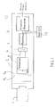
- the camera has a lens 1 mounted in a casing 2, which contains a sensor comprising a CCD array 3 coupled by optical fibres 4 to the phosphors on the output surface of an image intensifier 5 at the focal plane of which filter means F 3 , F 4 is cemented (the position of the filters has been exploded for clarity in Figures 1 and 2), the front part of the image intensifier also including a fibre optic coupling.
- F 1 is a correction filter which converts the spectral response of the sensor (i.e. the intensifier) to nominally photopic.
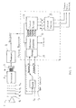
- the output of the CCD 3 undergoes processing in circuit 11 to produce a raw video output and then subsequent colour processing in circuit 12 to produce colour video outputs.
- the CCD 3 and the image intensifier 5 being electro-optic devices, the spatial pattern of the colours of the filter means F 3 , F 4 imaged onto the CCD 3 will not change with age or temperature and remains fixed once the camera has been manufactured.
- the colour processing uses stored signals based upon the response of the sensor to reference colours. These signals are generated after manufacture of each camera by means of test circuit 13. Once the signals have been stored, the test circuit is disconnected and the camera needs no further adjustment. If the intensifier were to be replaced over the lifetime of the camera, the manufacturer would have to reconnect the test circuit to programme in new stored signals.
- the CCD 3 is a solid state device in the form of an array, a certain number of pixels to each line and a certain number of lines in the array.
- the scene is imaged in normal video fashion in frames, each consisting of two consecutive interlaced fields.
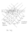
- the filter F 3 consists of diagonal yellow (Ye) stripes, the width and the spacing of which are equal to each other. In other words, between the stripes the filter is transparent (indicated W for white in the drawings).
- the filter F 4 consists of similarly arranged cyan (Cy) stripes spaced by transparent stripes. When the two filters are superimposed, a repeating pattern of four elemental colours is formed, as in the prior arrangements noted earlier.
- the kth pixel receives light from the image which has passed through the cyan filter, and so does the k+1 th pixel.
- the next pixel, the k+2 th partly receives imaging light through the cyan filter, and partly receives light through the transparent (white) filter.
- the k+3 rd and k+4 th pixels receive imaging light through the transparent filter.
- the next pixel (k+5 th ) receives imaging light partly through the transparent filter and partly through the yellow filter, while the next two pixels receive light through the yellow filter.
- the pixels of the n th line receive cyan, white, yellow and green, in a repeating sequence, as shown in Figure 4e.
- the effect of the pixels which receive light from two filter areas can be reduced by taking the average of two lines for each of the yellow cyan and green signals.
- the sequence of colours regularly repeats.
- the sequence of colours exposed on the pixels again regularly repeats, but the sequence is now different.
- the k th , k+1 th and k+2 th pixels receive light from the scene exposed through a cyan filter, the next two pixels, the k+3 rd and the k+4 th lie at the intersection of four filters, while the next four receive light through the yellow filter.
- the sequence for row n+1 is cyan, yellow, green.
- each line for this hypothetical situation of no distortion, the pixels of each line are illuminated by areas of light, the colour of which varies in a fixed repeating sequence.
- the raw video consisting of consecutive lines of each field is decoded in the sense of identifying those parts of a line which correspond to the scene viewed through each one of the four colours by using stored signals which are representative of the raw video output when the regularly repeating stripes are illuminated with primary reference colours.
- the camera is first imaged on a uniform primary blue scene. Cyan, which is a combination of blue and green, will be transparent to the blue, whereas yellow, which consists of red and green light, does not pass blue light, and so the result will be (referring to Figure 4f) blue regions which extend diagonally from the top of the drawing to the left of the drawing interspersed with similarly inclined dark regions. The blue stripes will result in the approximate sinusoidal variation shown for the fragment of one line in Figure 4a.
- the raw video from the CCD 3 is stored for a complete frame. What happens is that the approximately sinusoidal modulation passes through a slicer circuit 14 which produces waveform A from Figure 4a and waveform B from Figure 4c. These two waveforms are programmed into a memory 15 in the camera, each for a complete frame.
- the waveform generator 16 employs combinational logic on waveforms 4a and 4b to produce four waveforms, each containing just the pulses corresponding to one of the four colours i.e. yellow, green, cyan or white ( Figure 4e). For example, logic "and” produces the pulses corresponding to white illumination, logic “not-or” produces an output corresponding to green illumination, and so on.
- the memory contains, for each line of each frame, pulse trains which indicate the precise points in time at which the raw video corresponds to illumination by the respective colour.
- the memory may be a preprogrammed memory i.e. PROM or EPROM (which selects parts of the waveform according to spatial location). This is used then to separate out the colour components from the raw video from an actual scene.
- the raw video for one particular colour of the actual scene enters the sample and hold, which is controlled by pulses for that colour which are generated by the waveform generator using combinational logic from waveforms A and B in the memory.
- One line of the scene may be as shown in Figure 6a and the pulses which occur at the times when that line of the CCD are illuminated by one of the four colours shown in Figure 6b.
- the output of the sample and hold is as illustrated schematically in Figure 6c.
- the low resolution luminance signal leaving box 11 (Processing) would represent the grey scale intensity of the scene, but would have the stripe pattern visible on it, forming a pattern as in Fig 4g, but with various grey levels for the cyan, yellow and green areas.
- the matrix addition circuitry 10 removes the visibility of this stripe pattern from the raw video signal, producing a luminance signal having a bandwidth occupying a significant proportion of the video bandwidth.
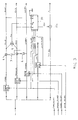
- the matrix addition circuitry 10 is gated by the cyan, yellow and green pulses to produce the appropriate ⁇ c for the appropriate part of the raw video waveform.
- ⁇ c is added to the raw video at those instants to reflect the fact that the raw video is considerably reduced in intensity because the red and blue components have been stopped.
- ⁇ c is zero when the white pulses arrive at the matrix addition circuitry.
- the action of the sample and hold circuits convert the incoming modulated waveforms into continuous waveform components of cyan, yellow and green without any discontinuities (i.e. gaps).
- the action of the adders 6, 7 produces the full set of primary signals, red, blue (and green), which are also continuous waveforms.
- the matrix addition circuitry 10 may include a clipping circuit to restrict ⁇ c to 30% input white (Y) level at times when cyan is subtracted. Then if a noise spike is generated in the matrix addition circuitry 10, the noise spike is limited. Similarly, ⁇ c can be restricted to 10% (of Y) at times when yellow is subtracted (see Figures 7 and 8).
- the corrected luminance signal may be further improved by passage through a comb filter to remove residual colour energy.
- the luminance comb "stop bands" occur at frequency locations which are in between line harmonics. These locations depend on stripe angle and geometry errors.
- the benefit of the colour separation technique described is that significant suppression is achieved with poor geometry sensors. Further inclusion of a comb filter enables even better suppression and reduction of noise (both random and static). Poor geometry sensors could not use comb filters without the colour separator herein described.
- the camera used for producing colour should have the following features, crystal timing, unity gamma, and good modulation at the highest stripe spatial frequency (i.e. 50% at 3.7MHz).
- the red, green, blue and luminance signals pass from the Colour Decode 17 into Colour Encode 18.
- Gamma correction is performed in this circuit, and a high pass filtered version of the luminance signal is added to each of the low resolution red, green and blue channels to produce three high resolution outputs (known as "mixed high” processing).
- the output of Colour Encode 18 is in three groups. The first group is three channels of red, green and blue video outputs together with synchronising waveforms.
- the second group is two channels of the luminance signal (Y) and the chrominance signal (C).
- the third group of channels is a single channel which is used to encode either PAL, NTSC or SECAM.
- Outgoing video from the decoder is T.V. standard encoded to suit external equipment (i.e. TV displays, video recording, r.f. links etc.).
- the waveform generator 16 is also responsible for generating TV pulses such as synchronisation pulses, blanking pulses and clamping pulses etc.
- a typical resolution of the CCD array could be around 600 pixels by 600 lines.
- the maximum frequency which can be resolved along the lines would correspond to alternate black and white values i.e. 300 periods in 52 ⁇ s i.e. a maximum frequency of around 6MHz.
- the response of the intensifier falls as the frequency increases and, for this reason, a typical frequency for, say, the cyan stripe is 3MHz. This would correspond to two pixels for the cyan stripes, alternating with two for the interposed transparent stripes.
- Defocus filter F 2 reduces alias disturbance of scene detail, and may be a lenticule, birefringent plate, Savart plate or cylindrical lens. For surveillance use (i.e. long focal length lenses, zoom lenses etc) this filter can be omitted.
- the shading errors of the intensifier are a fixed signature of the sensor and can thus be optically corrected.
- the shading errors can be measured (see the roll-off at the end of the line in Figure 4a), and an inverse profile pattern can be produced (by for example a computer line transparency printer). It is beneficial to perform shading correction optically using filter F 5 rather than electronically as this avoids errors from scenes of low contrast.
- the innovations are the method of deriving the sample patterns, the method of storing the sample patterns, the method of removing colour errors from luminance signals (i.e. Ac cancellation), the method of removing luma errors from chroma signals (i.e. colour separation) and the method to remove shading.
- improved luma cross-talk i.e. the rejection of colour signals onto the luma channel will be constant over the total area of the picture
- improved chroma cross-talk the rejection of colour cross-talk of one colour onto another will be constant over the total picture area (colour shading will not arise or "constant luminance" will exist)
- the rejection performance will not degrade with either temperature or age (a feature of intensifiers)
- the technique can be implemented by totally digital techniques (i.e. low cost, small size and stable performance); the intensified colour pattern can be small in size, low on power and low cost; improved rejection can be achieved by adding further filtering by using one or two TV line comb filters; white highlights in the scene or dark parts ofa scene will not be coloured "green” i.e.
- the system has a desirable "fade-to-grey" feature; choice of striped filters is not dependent upon compromising performance e.g. stripe angles could be ⁇ 45° for NTSC systems, ⁇ 22.5° for PAL systems or even between ⁇ 20° to ⁇ 30°.
- the pitch stripe frequency can be the same for both colours (cyan and yellow). This allows the stripe frequency to be low (e.g. 2.5 MHz), thereby allowing the use of poor resolution modulation transfer function sensors such as intensifiers; the colour beat pattern i.e.
- intensifier types for use with this technique are: first generation; second generation; or electron bombarded CCD.
- Intensifiers with a cover glass e.g. third generation
- the relay lens puts the filter at the focus of the relay lens which is itself focuses at the focus of the intensifier. All sensors should have a linear transfer function i.e. unity gamma.
- the camera is not limited to use with an intensifier, and could be used on a CCD without the intensifier. Further, types of solid state sensor other than CCD could be used.
- the invention is applicable to wavelengths outside the visible range, for example the infra-red range where the filters F 3 and F 4 will correspond to particular infra-red spectral regions in the way that the yellow and cyan stripes correspond to particular visible regions, resulting in a false colour picture where objects emitting in three different frequency ranges are separately shown.
Landscapes
- Engineering & Computer Science (AREA)
- Multimedia (AREA)
- Signal Processing (AREA)
- Physics & Mathematics (AREA)
- Spectroscopy & Molecular Physics (AREA)
- Color Television Image Signal Generators (AREA)
Applications Claiming Priority (2)
| Application Number | Priority Date | Filing Date | Title |
|---|---|---|---|
| GBGB9620838.4A GB9620838D0 (en) | 1996-10-02 | 1996-10-02 | A camera |
| GB9620838 | 1996-10-02 |
Publications (3)
| Publication Number | Publication Date |
|---|---|
| EP0835030A2 true EP0835030A2 (fr) | 1998-04-08 |
| EP0835030A3 EP0835030A3 (fr) | 2000-03-15 |
| EP0835030B1 EP0835030B1 (fr) | 2003-09-10 |
Family
ID=10801031
Family Applications (1)
| Application Number | Title | Priority Date | Filing Date |
|---|---|---|---|
| EP97307811A Expired - Lifetime EP0835030B1 (fr) | 1996-10-02 | 1997-10-02 | Caméra de télévision en couleur |
Country Status (5)
| Country | Link |
|---|---|
| US (1) | US6633333B1 (fr) |
| EP (1) | EP0835030B1 (fr) |
| JP (1) | JPH10200905A (fr) |
| DE (1) | DE69724725T2 (fr) |
| GB (2) | GB9620838D0 (fr) |
Cited By (1)
| Publication number | Priority date | Publication date | Assignee | Title |
|---|---|---|---|---|
| EP1694057A3 (fr) * | 2005-02-21 | 2010-05-05 | E2V Technologies (UK) Limited | Caméra couleur a faible niveau de lumière |
Families Citing this family (8)
| Publication number | Priority date | Publication date | Assignee | Title |
|---|---|---|---|---|
| GB9620838D0 (en) * | 1996-10-02 | 1996-11-20 | Marconi Gec Ltd | A camera |
| US7057647B1 (en) * | 2000-06-14 | 2006-06-06 | E-Watch, Inc. | Dual-mode camera system for day/night or variable zoom operation |
| GB2341029B (en) * | 1998-08-29 | 2002-12-31 | Marconi Gec Ltd | Cameras |
| US6515764B1 (en) * | 1998-12-18 | 2003-02-04 | Xerox Corporation | Method and apparatus for detecting photocopier tracking signatures |
| US7698450B2 (en) | 2000-11-17 | 2010-04-13 | Monroe David A | Method and apparatus for distributing digitized streaming video over a network |
| TWI309531B (en) * | 2006-01-19 | 2009-05-01 | Realtek Semiconductor Corp | Waveform generator and related method thereof |
| KR100877069B1 (ko) * | 2007-04-23 | 2009-01-09 | 삼성전자주식회사 | 이미지 촬상 장치 및 방법 |
| DE202007019236U1 (de) | 2007-11-02 | 2011-11-09 | Valentina Anzupowa | Farbteiler-Bildwandler-Gruppe mit teildurchlässigen Spiegeln und Mosaikfarbfiltern |
Family Cites Families (26)
| Publication number | Priority date | Publication date | Assignee | Title |
|---|---|---|---|---|
| GB1410765A (en) * | 1971-10-08 | 1975-10-22 | Emi Ltd | Colour television cameras |
| CH556625A (de) * | 1972-09-06 | 1974-11-29 | Siemens Ag | Einroehren-farbfernsehkamera mit farbstreifenfiltern. |
| US4064532A (en) * | 1974-09-18 | 1977-12-20 | Sony Corporation | Solid state color camera |
| US4065785A (en) * | 1976-06-28 | 1977-12-27 | Texas Instruments Incorporated | Single sensor time encoded color imaging system |
| US4107732A (en) * | 1976-06-28 | 1978-08-15 | Texas Instruments Incorporated | Two sensor time encoded color imaging system |
| US4141036A (en) * | 1977-03-10 | 1979-02-20 | General Electric Company | Solid state color camera |
| GB2014397B (en) * | 1978-02-10 | 1982-08-18 | Hitachi Ltd | Solid-state colour imaging device |
| JPS5911309B2 (ja) * | 1978-03-03 | 1984-03-14 | 日本ビクター株式会社 | カラ−テレビジヨン信号発生装置 |
| US4288812A (en) * | 1979-11-19 | 1981-09-08 | Rca Corporation | Color filter |
| JPS56116783U (fr) * | 1980-02-04 | 1981-09-07 | ||
| GB2086179B (en) * | 1980-10-08 | 1984-09-19 | Victor Company Of Japan | Color television camera having a color separation crossing striped filter |
| US4404587A (en) * | 1981-12-04 | 1983-09-13 | Rca Corporation | Electrical compensation for misregistration of striped color filter in a color imager with discrete sampling elements |
| JPH0620316B2 (ja) * | 1982-05-17 | 1994-03-16 | 株式会社日立製作所 | 撮像光学系 |
| JPS59153392A (ja) | 1983-02-22 | 1984-09-01 | Victor Co Of Japan Ltd | カラ−撮像装置 |
| US4591900A (en) * | 1983-03-14 | 1986-05-27 | Rca Corporation | Encoding pattern for single chip CCD camera processing scheme |
| US4630105A (en) * | 1984-07-31 | 1986-12-16 | Rca Corporation | Symmetric color encoding shift pattern for a solid-state imager camera and decoding scheme therefor |
| KR900004964B1 (ko) | 1984-10-06 | 1990-07-12 | 니뽕 빅터 가부시끼 가이샤 | 칼라 촬상장치 |
| US4855816A (en) | 1984-10-23 | 1989-08-08 | Victor Company Of Japan, Ltd. | Color imaging apparatus including phase control system for maintaining start positions of scanning lines equal to start positions of reference values thereof |
| KR900002386B1 (ko) | 1984-10-23 | 1990-04-13 | 니뽕 빅터 가부시끼가이샤 | 칼라 촬상장치 |
| EP0180946B1 (fr) | 1984-11-02 | 1991-06-19 | Victor Company Of Japan, Limited | Appareil de prises de vues en couleur |
| EP0274820B1 (fr) | 1986-10-15 | 1992-04-15 | Victor Company Of Japan, Limited | Caméra de télévision en couleurs |
| US5457494A (en) * | 1988-11-21 | 1995-10-10 | Canon Kabushiki Kaisha | Image pickup signal processing apparatus |
| DE3936930C1 (fr) * | 1989-11-06 | 1990-05-17 | Proxitronic Funk Gmbh & Co Kg, 6140 Bensheim, De | |
| JPH05304679A (ja) * | 1992-04-27 | 1993-11-16 | Sony Corp | カラーカメラの信号処理回路におけるレベルバランス回路 |
| US5541653A (en) * | 1993-07-27 | 1996-07-30 | Sri International | Method and appartus for increasing resolution of digital color images using correlated decoding |
| GB9620838D0 (en) * | 1996-10-02 | 1996-11-20 | Marconi Gec Ltd | A camera |
-
1996
- 1996-10-02 GB GBGB9620838.4A patent/GB9620838D0/en active Pending
-
1997
- 1997-10-01 US US08/942,538 patent/US6633333B1/en not_active Expired - Lifetime
- 1997-10-02 GB GB9720896A patent/GB2318012B/en not_active Revoked
- 1997-10-02 EP EP97307811A patent/EP0835030B1/fr not_active Expired - Lifetime
- 1997-10-02 DE DE69724725T patent/DE69724725T2/de not_active Expired - Fee Related
- 1997-10-02 JP JP9306300A patent/JPH10200905A/ja active Pending
Cited By (1)
| Publication number | Priority date | Publication date | Assignee | Title |
|---|---|---|---|---|
| EP1694057A3 (fr) * | 2005-02-21 | 2010-05-05 | E2V Technologies (UK) Limited | Caméra couleur a faible niveau de lumière |
Also Published As
| Publication number | Publication date |
|---|---|
| DE69724725D1 (de) | 2003-10-16 |
| GB9620838D0 (en) | 1996-11-20 |
| GB2318012A (en) | 1998-04-08 |
| JPH10200905A (ja) | 1998-07-31 |
| DE69724725T2 (de) | 2004-08-19 |
| EP0835030A3 (fr) | 2000-03-15 |
| GB9720896D0 (en) | 1997-12-03 |
| US6633333B1 (en) | 2003-10-14 |
| EP0835030B1 (fr) | 2003-09-10 |
| GB2318012B (en) | 2000-05-24 |
Similar Documents
| Publication | Publication Date | Title |
|---|---|---|
| CN1177467C (zh) | 具有红外校正功能的彩色成像系统及其成像方法 | |
| US4967264A (en) | Color sequential optical offset image sampling system | |
| US4163247A (en) | Color television camera with time multiplexing of luminance and chrominance information | |
| JPS63155893A (ja) | 映像信号の形成装置 | |
| JPS6359587B2 (fr) | ||
| GB2107151A (en) | Television systems and subsystems therefor | |
| EP0835030B1 (fr) | Caméra de télévision en couleur | |
| US20030151685A1 (en) | Digital video camera having only two CCDs | |
| US4107732A (en) | Two sensor time encoded color imaging system | |
| KR100841895B1 (ko) | 이미지 센서 및 컬러 카메라 | |
| EP0449325B1 (fr) | Filtre optique passe-bas | |
| EP1035729A2 (fr) | Méthode et dispositif de capture d'image | |
| US6356672B1 (en) | Method and apparatus for reducing the color registration artifact of image capture devices | |
| SU1277913A3 (ru) | Способ оптико-электронной передачи цветного изображени | |
| WO1992013423A1 (fr) | Capteurs d'images en couleurs a solide utilisant une configuration de filtres couleurs a decalage de trames | |
| JPH0316837B2 (fr) | ||
| US3840696A (en) | Single tube color television camera with recovery of index signal for elemental color component separation | |
| US3619489A (en) | Shadowing system for color encoding camera | |
| US3651250A (en) | Television camera utilizing a parallel-striped color encoding filter | |
| US3757033A (en) | Shadowing system for color encoding camera | |
| US3647947A (en) | Chrominance signal generator having a patterned filter | |
| JPH0250675B2 (fr) | ||
| US3745237A (en) | Color television camera equipment having a reference filter and a color filter assembly interposed between the camera and subject | |
| JPS6362492A (ja) | カラ−画像用固体撮像素子 | |
| JPH0528037B2 (fr) |
Legal Events
| Date | Code | Title | Description |
|---|---|---|---|
| PUAI | Public reference made under article 153(3) epc to a published international application that has entered the european phase |
Free format text: ORIGINAL CODE: 0009012 |
|
| AK | Designated contracting states |
Kind code of ref document: A2 Designated state(s): CH DE FR GB IT LI NL SE |
|
| AX | Request for extension of the european patent |
Free format text: AL;LT;LV;RO;SI |
|
| PUAL | Search report despatched |
Free format text: ORIGINAL CODE: 0009013 |
|
| AK | Designated contracting states |
Kind code of ref document: A3 Designated state(s): AT BE CH DE DK ES FI FR GB GR IE IT LI LU MC NL PT SE |
|
| AX | Request for extension of the european patent |
Free format text: AL;LT;LV;RO;SI |
|
| RIC1 | Information provided on ipc code assigned before grant |
Free format text: 7H 04N 9/04 A, 7H 04N 9/077 B |
|
| RTI1 | Title (correction) |
Free format text: COLOUR TV CAMERA |
|
| 17P | Request for examination filed |
Effective date: 20000719 |
|
| 17Q | First examination report despatched |
Effective date: 20000830 |
|
| AKX | Designation fees paid |
Free format text: CH DE FR GB IT LI NL SE |
|
| RAP1 | Party data changed (applicant data changed or rights of an application transferred) |
Owner name: BAE SYSTEMS ELECTRONICS LTD. |
|
| GRAG | Despatch of communication of intention to grant |
Free format text: ORIGINAL CODE: EPIDOS AGRA |
|
| GRAG | Despatch of communication of intention to grant |
Free format text: ORIGINAL CODE: EPIDOS AGRA |
|
| GRAH | Despatch of communication of intention to grant a patent |
Free format text: ORIGINAL CODE: EPIDOS IGRA |
|
| GRAH | Despatch of communication of intention to grant a patent |
Free format text: ORIGINAL CODE: EPIDOS IGRA |
|
| GRAA | (expected) grant |
Free format text: ORIGINAL CODE: 0009210 |
|
| AK | Designated contracting states |
Kind code of ref document: B1 Designated state(s): CH DE FR GB IT LI NL SE |
|
| PG25 | Lapsed in a contracting state [announced via postgrant information from national office to epo] |
Ref country code: LI Free format text: LAPSE BECAUSE OF FAILURE TO SUBMIT A TRANSLATION OF THE DESCRIPTION OR TO PAY THE FEE WITHIN THE PRESCRIBED TIME-LIMIT Effective date: 20030910 Ref country code: IT Free format text: LAPSE BECAUSE OF FAILURE TO SUBMIT A TRANSLATION OF THE DESCRIPTION OR TO PAY THE FEE WITHIN THE PRESCRIBED TIME-LIMIT;WARNING: LAPSES OF ITALIAN PATENTS WITH EFFECTIVE DATE BEFORE 2007 MAY HAVE OCCURRED AT ANY TIME BEFORE 2007. THE CORRECT EFFECTIVE DATE MAY BE DIFFERENT FROM THE ONE RECORDED. Effective date: 20030910 Ref country code: CH Free format text: LAPSE BECAUSE OF FAILURE TO SUBMIT A TRANSLATION OF THE DESCRIPTION OR TO PAY THE FEE WITHIN THE PRESCRIBED TIME-LIMIT Effective date: 20030910 |
|
| REG | Reference to a national code |
Ref country code: GB Ref legal event code: FG4D |
|
| REG | Reference to a national code |
Ref country code: CH Ref legal event code: EP |
|
| REF | Corresponds to: |
Ref document number: 69724725 Country of ref document: DE Date of ref document: 20031016 Kind code of ref document: P |
|
| PGFP | Annual fee paid to national office [announced via postgrant information from national office to epo] |
Ref country code: CH Payment date: 20031017 Year of fee payment: 7 |
|
| REG | Reference to a national code |
Ref country code: GB Ref legal event code: 732E |
|
| PG25 | Lapsed in a contracting state [announced via postgrant information from national office to epo] |
Ref country code: SE Free format text: LAPSE BECAUSE OF FAILURE TO SUBMIT A TRANSLATION OF THE DESCRIPTION OR TO PAY THE FEE WITHIN THE PRESCRIBED TIME-LIMIT Effective date: 20031210 |
|
| REG | Reference to a national code |
Ref country code: CH Ref legal event code: PL |
|
| ET | Fr: translation filed | ||
| PLBE | No opposition filed within time limit |
Free format text: ORIGINAL CODE: 0009261 |
|
| STAA | Information on the status of an ep patent application or granted ep patent |
Free format text: STATUS: NO OPPOSITION FILED WITHIN TIME LIMIT |
|
| 26N | No opposition filed |
Effective date: 20040614 |
|
| REG | Reference to a national code |
Ref country code: FR Ref legal event code: TP |
|
| REG | Reference to a national code |
Ref country code: FR Ref legal event code: CD Ref country code: FR Ref legal event code: CA |
|
| NLS | Nl: assignments of ep-patents |
Owner name: E2V TECHNOLOGIES LIMITED |
|
| NLT1 | Nl: modifications of names registered in virtue of documents presented to the patent office pursuant to art. 16 a, paragraph 1 |
Owner name: E2V TECHNOLOGIES (UK) LIMITED |
|
| PGFP | Annual fee paid to national office [announced via postgrant information from national office to epo] |
Ref country code: NL Payment date: 20081005 Year of fee payment: 12 |
|
| PGFP | Annual fee paid to national office [announced via postgrant information from national office to epo] |
Ref country code: DE Payment date: 20081014 Year of fee payment: 12 |
|
| PGFP | Annual fee paid to national office [announced via postgrant information from national office to epo] |
Ref country code: FR Payment date: 20081014 Year of fee payment: 12 |
|
| REG | Reference to a national code |
Ref country code: NL Ref legal event code: V1 Effective date: 20100501 |
|
| REG | Reference to a national code |
Ref country code: FR Ref legal event code: ST Effective date: 20100630 |
|
| PG25 | Lapsed in a contracting state [announced via postgrant information from national office to epo] |
Ref country code: NL Free format text: LAPSE BECAUSE OF NON-PAYMENT OF DUE FEES Effective date: 20100501 Ref country code: FR Free format text: LAPSE BECAUSE OF NON-PAYMENT OF DUE FEES Effective date: 20091102 Ref country code: DE Free format text: LAPSE BECAUSE OF NON-PAYMENT OF DUE FEES Effective date: 20100501 |
|
| PGFP | Annual fee paid to national office [announced via postgrant information from national office to epo] |
Ref country code: GB Payment date: 20120926 Year of fee payment: 16 |
|
| GBPC | Gb: european patent ceased through non-payment of renewal fee |
Effective date: 20131002 |
|
| PG25 | Lapsed in a contracting state [announced via postgrant information from national office to epo] |
Ref country code: GB Free format text: LAPSE BECAUSE OF NON-PAYMENT OF DUE FEES Effective date: 20131002 |