EP0835178B1 - Controleur de soudage - Google Patents
Controleur de soudage Download PDFInfo
- Publication number
- EP0835178B1 EP0835178B1 EP19960915804 EP96915804A EP0835178B1 EP 0835178 B1 EP0835178 B1 EP 0835178B1 EP 19960915804 EP19960915804 EP 19960915804 EP 96915804 A EP96915804 A EP 96915804A EP 0835178 B1 EP0835178 B1 EP 0835178B1
- Authority
- EP
- European Patent Office
- Prior art keywords
- weld
- horn
- force
- welding
- measuring
- Prior art date
- Legal status (The legal status is an assumption and is not a legal conclusion. Google has not performed a legal analysis and makes no representation as to the accuracy of the status listed.)
- Expired - Lifetime
Links
- 238000003466 welding Methods 0.000 title claims abstract description 90
- 239000000463 material Substances 0.000 claims abstract description 5
- 238000000034 method Methods 0.000 claims description 19
- 230000004044 response Effects 0.000 claims description 13
- 238000006073 displacement reaction Methods 0.000 abstract description 9
- 230000001276 controlling effect Effects 0.000 description 7
- 239000012530 fluid Substances 0.000 description 6
- 230000008569 process Effects 0.000 description 6
- 230000008859 change Effects 0.000 description 5
- 230000007246 mechanism Effects 0.000 description 5
- 229910000831 Steel Inorganic materials 0.000 description 4
- 238000013461 design Methods 0.000 description 4
- 229920003023 plastic Polymers 0.000 description 4
- 239000004033 plastic Substances 0.000 description 4
- 239000010959 steel Substances 0.000 description 4
- 230000005291 magnetic effect Effects 0.000 description 3
- 230000000007 visual effect Effects 0.000 description 3
- PXHVJJICTQNCMI-UHFFFAOYSA-N Nickel Chemical compound [Ni] PXHVJJICTQNCMI-UHFFFAOYSA-N 0.000 description 2
- 230000001133 acceleration Effects 0.000 description 2
- 230000003247 decreasing effect Effects 0.000 description 2
- 239000004744 fabric Substances 0.000 description 2
- 239000000155 melt Substances 0.000 description 2
- 230000001105 regulatory effect Effects 0.000 description 2
- RTAQQCXQSZGOHL-UHFFFAOYSA-N Titanium Chemical compound [Ti] RTAQQCXQSZGOHL-UHFFFAOYSA-N 0.000 description 1
- 230000004913 activation Effects 0.000 description 1
- XAGFODPZIPBFFR-UHFFFAOYSA-N aluminium Chemical compound [Al] XAGFODPZIPBFFR-UHFFFAOYSA-N 0.000 description 1
- 229910052782 aluminium Inorganic materials 0.000 description 1
- 238000013459 approach Methods 0.000 description 1
- 238000010276 construction Methods 0.000 description 1
- 230000007423 decrease Effects 0.000 description 1
- 230000001419 dependent effect Effects 0.000 description 1
- 230000000694 effects Effects 0.000 description 1
- 230000008713 feedback mechanism Effects 0.000 description 1
- 229940090441 infed Drugs 0.000 description 1
- 238000005304 joining Methods 0.000 description 1
- WABPQHHGFIMREM-UHFFFAOYSA-N lead(0) Chemical compound [Pb] WABPQHHGFIMREM-UHFFFAOYSA-N 0.000 description 1
- 238000004519 manufacturing process Methods 0.000 description 1
- 238000005259 measurement Methods 0.000 description 1
- 239000000203 mixture Substances 0.000 description 1
- 238000012544 monitoring process Methods 0.000 description 1
- 229910052759 nickel Inorganic materials 0.000 description 1
- 230000010355 oscillation Effects 0.000 description 1
- 238000004023 plastic welding Methods 0.000 description 1
- 229920000642 polymer Polymers 0.000 description 1
- 230000003134 recirculating effect Effects 0.000 description 1
- 238000007789 sealing Methods 0.000 description 1
- 239000010936 titanium Substances 0.000 description 1
- 229910052719 titanium Inorganic materials 0.000 description 1
Images

Classifications
-
- B—PERFORMING OPERATIONS; TRANSPORTING
- B29—WORKING OF PLASTICS; WORKING OF SUBSTANCES IN A PLASTIC STATE IN GENERAL
- B29C—SHAPING OR JOINING OF PLASTICS; SHAPING OF MATERIAL IN A PLASTIC STATE, NOT OTHERWISE PROVIDED FOR; AFTER-TREATMENT OF THE SHAPED PRODUCTS, e.g. REPAIRING
- B29C66/00—General aspects of processes or apparatus for joining preformed parts
- B29C66/90—Measuring or controlling the joining process
- B29C66/96—Measuring or controlling the joining process characterised by the method for implementing the controlling of the joining process
-
- B—PERFORMING OPERATIONS; TRANSPORTING
- B29—WORKING OF PLASTICS; WORKING OF SUBSTANCES IN A PLASTIC STATE IN GENERAL
- B29C—SHAPING OR JOINING OF PLASTICS; SHAPING OF MATERIAL IN A PLASTIC STATE, NOT OTHERWISE PROVIDED FOR; AFTER-TREATMENT OF THE SHAPED PRODUCTS, e.g. REPAIRING
- B29C65/00—Joining or sealing of preformed parts, e.g. welding of plastics materials; Apparatus therefor
- B29C65/02—Joining or sealing of preformed parts, e.g. welding of plastics materials; Apparatus therefor by heating, with or without pressure
- B29C65/08—Joining or sealing of preformed parts, e.g. welding of plastics materials; Apparatus therefor by heating, with or without pressure using ultrasonic vibrations
-
- B—PERFORMING OPERATIONS; TRANSPORTING
- B29—WORKING OF PLASTICS; WORKING OF SUBSTANCES IN A PLASTIC STATE IN GENERAL
- B29C—SHAPING OR JOINING OF PLASTICS; SHAPING OF MATERIAL IN A PLASTIC STATE, NOT OTHERWISE PROVIDED FOR; AFTER-TREATMENT OF THE SHAPED PRODUCTS, e.g. REPAIRING
- B29C66/00—General aspects of processes or apparatus for joining preformed parts
- B29C66/90—Measuring or controlling the joining process
- B29C66/92—Measuring or controlling the joining process by measuring or controlling the pressure, the force, the mechanical power or the displacement of the joining tools
- B29C66/922—Measuring or controlling the joining process by measuring or controlling the pressure, the force, the mechanical power or the displacement of the joining tools by measuring the pressure, the force, the mechanical power or the displacement of the joining tools
- B29C66/9221—Measuring or controlling the joining process by measuring or controlling the pressure, the force, the mechanical power or the displacement of the joining tools by measuring the pressure, the force, the mechanical power or the displacement of the joining tools by measuring the pressure, the force or the mechanical power
-
- B—PERFORMING OPERATIONS; TRANSPORTING
- B29—WORKING OF PLASTICS; WORKING OF SUBSTANCES IN A PLASTIC STATE IN GENERAL
- B29C—SHAPING OR JOINING OF PLASTICS; SHAPING OF MATERIAL IN A PLASTIC STATE, NOT OTHERWISE PROVIDED FOR; AFTER-TREATMENT OF THE SHAPED PRODUCTS, e.g. REPAIRING
- B29C66/00—General aspects of processes or apparatus for joining preformed parts
- B29C66/90—Measuring or controlling the joining process
- B29C66/92—Measuring or controlling the joining process by measuring or controlling the pressure, the force, the mechanical power or the displacement of the joining tools
- B29C66/924—Measuring or controlling the joining process by measuring or controlling the pressure, the force, the mechanical power or the displacement of the joining tools by controlling or regulating the pressure, the force, the mechanical power or the displacement of the joining tools
- B29C66/9241—Measuring or controlling the joining process by measuring or controlling the pressure, the force, the mechanical power or the displacement of the joining tools by controlling or regulating the pressure, the force, the mechanical power or the displacement of the joining tools by controlling or regulating the pressure, the force or the mechanical power
-
- B—PERFORMING OPERATIONS; TRANSPORTING
- B29—WORKING OF PLASTICS; WORKING OF SUBSTANCES IN A PLASTIC STATE IN GENERAL
- B29C—SHAPING OR JOINING OF PLASTICS; SHAPING OF MATERIAL IN A PLASTIC STATE, NOT OTHERWISE PROVIDED FOR; AFTER-TREATMENT OF THE SHAPED PRODUCTS, e.g. REPAIRING
- B29C66/00—General aspects of processes or apparatus for joining preformed parts
- B29C66/90—Measuring or controlling the joining process
- B29C66/92—Measuring or controlling the joining process by measuring or controlling the pressure, the force, the mechanical power or the displacement of the joining tools
- B29C66/924—Measuring or controlling the joining process by measuring or controlling the pressure, the force, the mechanical power or the displacement of the joining tools by controlling or regulating the pressure, the force, the mechanical power or the displacement of the joining tools
- B29C66/9261—Measuring or controlling the joining process by measuring or controlling the pressure, the force, the mechanical power or the displacement of the joining tools by controlling or regulating the pressure, the force, the mechanical power or the displacement of the joining tools by controlling or regulating the displacement of the joining tools
-
- B—PERFORMING OPERATIONS; TRANSPORTING
- B29—WORKING OF PLASTICS; WORKING OF SUBSTANCES IN A PLASTIC STATE IN GENERAL
- B29C—SHAPING OR JOINING OF PLASTICS; SHAPING OF MATERIAL IN A PLASTIC STATE, NOT OTHERWISE PROVIDED FOR; AFTER-TREATMENT OF THE SHAPED PRODUCTS, e.g. REPAIRING
- B29C66/00—General aspects of processes or apparatus for joining preformed parts
- B29C66/90—Measuring or controlling the joining process
- B29C66/93—Measuring or controlling the joining process by measuring or controlling the speed
- B29C66/932—Measuring or controlling the joining process by measuring or controlling the speed by measuring the speed
-
- B—PERFORMING OPERATIONS; TRANSPORTING
- B29—WORKING OF PLASTICS; WORKING OF SUBSTANCES IN A PLASTIC STATE IN GENERAL
- B29C—SHAPING OR JOINING OF PLASTICS; SHAPING OF MATERIAL IN A PLASTIC STATE, NOT OTHERWISE PROVIDED FOR; AFTER-TREATMENT OF THE SHAPED PRODUCTS, e.g. REPAIRING
- B29C66/00—General aspects of processes or apparatus for joining preformed parts
- B29C66/90—Measuring or controlling the joining process
- B29C66/93—Measuring or controlling the joining process by measuring or controlling the speed
- B29C66/934—Measuring or controlling the joining process by measuring or controlling the speed by controlling or regulating the speed
- B29C66/93441—Measuring or controlling the joining process by measuring or controlling the speed by controlling or regulating the speed the speed being non-constant over time
-
- B—PERFORMING OPERATIONS; TRANSPORTING
- B29—WORKING OF PLASTICS; WORKING OF SUBSTANCES IN A PLASTIC STATE IN GENERAL
- B29C—SHAPING OR JOINING OF PLASTICS; SHAPING OF MATERIAL IN A PLASTIC STATE, NOT OTHERWISE PROVIDED FOR; AFTER-TREATMENT OF THE SHAPED PRODUCTS, e.g. REPAIRING
- B29C66/00—General aspects of processes or apparatus for joining preformed parts
- B29C66/90—Measuring or controlling the joining process
- B29C66/95—Measuring or controlling the joining process by measuring or controlling specific variables not covered by groups B29C66/91 - B29C66/94
- B29C66/951—Measuring or controlling the joining process by measuring or controlling specific variables not covered by groups B29C66/91 - B29C66/94 by measuring or controlling the vibration frequency and/or the vibration amplitude of vibrating joining tools, e.g. of ultrasonic welding tools
- B29C66/9511—Measuring or controlling the joining process by measuring or controlling specific variables not covered by groups B29C66/91 - B29C66/94 by measuring or controlling the vibration frequency and/or the vibration amplitude of vibrating joining tools, e.g. of ultrasonic welding tools by measuring their vibration frequency
-
- B—PERFORMING OPERATIONS; TRANSPORTING
- B29—WORKING OF PLASTICS; WORKING OF SUBSTANCES IN A PLASTIC STATE IN GENERAL
- B29C—SHAPING OR JOINING OF PLASTICS; SHAPING OF MATERIAL IN A PLASTIC STATE, NOT OTHERWISE PROVIDED FOR; AFTER-TREATMENT OF THE SHAPED PRODUCTS, e.g. REPAIRING
- B29C66/00—General aspects of processes or apparatus for joining preformed parts
- B29C66/90—Measuring or controlling the joining process
- B29C66/95—Measuring or controlling the joining process by measuring or controlling specific variables not covered by groups B29C66/91 - B29C66/94
- B29C66/951—Measuring or controlling the joining process by measuring or controlling specific variables not covered by groups B29C66/91 - B29C66/94 by measuring or controlling the vibration frequency and/or the vibration amplitude of vibrating joining tools, e.g. of ultrasonic welding tools
- B29C66/9516—Measuring or controlling the joining process by measuring or controlling specific variables not covered by groups B29C66/91 - B29C66/94 by measuring or controlling the vibration frequency and/or the vibration amplitude of vibrating joining tools, e.g. of ultrasonic welding tools by controlling their vibration amplitude
-
- B—PERFORMING OPERATIONS; TRANSPORTING
- B29—WORKING OF PLASTICS; WORKING OF SUBSTANCES IN A PLASTIC STATE IN GENERAL
- B29C—SHAPING OR JOINING OF PLASTICS; SHAPING OF MATERIAL IN A PLASTIC STATE, NOT OTHERWISE PROVIDED FOR; AFTER-TREATMENT OF THE SHAPED PRODUCTS, e.g. REPAIRING
- B29C66/00—General aspects of processes or apparatus for joining preformed parts
- B29C66/90—Measuring or controlling the joining process
- B29C66/95—Measuring or controlling the joining process by measuring or controlling specific variables not covered by groups B29C66/91 - B29C66/94
- B29C66/954—Measuring or controlling the joining process by measuring or controlling specific variables not covered by groups B29C66/91 - B29C66/94 by measuring or controlling the thickness of the parts to be joined
-
- B—PERFORMING OPERATIONS; TRANSPORTING
- B29—WORKING OF PLASTICS; WORKING OF SUBSTANCES IN A PLASTIC STATE IN GENERAL
- B29C—SHAPING OR JOINING OF PLASTICS; SHAPING OF MATERIAL IN A PLASTIC STATE, NOT OTHERWISE PROVIDED FOR; AFTER-TREATMENT OF THE SHAPED PRODUCTS, e.g. REPAIRING
- B29C66/00—General aspects of processes or apparatus for joining preformed parts
- B29C66/90—Measuring or controlling the joining process
- B29C66/96—Measuring or controlling the joining process characterised by the method for implementing the controlling of the joining process
- B29C66/961—Measuring or controlling the joining process characterised by the method for implementing the controlling of the joining process involving a feedback loop mechanism, e.g. comparison with a desired value
-
- B—PERFORMING OPERATIONS; TRANSPORTING
- B29—WORKING OF PLASTICS; WORKING OF SUBSTANCES IN A PLASTIC STATE IN GENERAL
- B29C—SHAPING OR JOINING OF PLASTICS; SHAPING OF MATERIAL IN A PLASTIC STATE, NOT OTHERWISE PROVIDED FOR; AFTER-TREATMENT OF THE SHAPED PRODUCTS, e.g. REPAIRING
- B29C66/00—General aspects of processes or apparatus for joining preformed parts
- B29C66/80—General aspects of machine operations or constructions and parts thereof
- B29C66/82—Pressure application arrangements, e.g. transmission or actuating mechanisms for joining tools or clamps
- B29C66/824—Actuating mechanisms
- B29C66/8242—Pneumatic or hydraulic drives
-
- B—PERFORMING OPERATIONS; TRANSPORTING
- B29—WORKING OF PLASTICS; WORKING OF SUBSTANCES IN A PLASTIC STATE IN GENERAL
- B29C—SHAPING OR JOINING OF PLASTICS; SHAPING OF MATERIAL IN A PLASTIC STATE, NOT OTHERWISE PROVIDED FOR; AFTER-TREATMENT OF THE SHAPED PRODUCTS, e.g. REPAIRING
- B29C66/00—General aspects of processes or apparatus for joining preformed parts
- B29C66/80—General aspects of machine operations or constructions and parts thereof
- B29C66/83—General aspects of machine operations or constructions and parts thereof characterised by the movement of the joining or pressing tools
- B29C66/836—Moving relative to and tangentially to the parts to be joined, e.g. transversely to the displacement of the parts to be joined, e.g. using a X-Y table
-
- B—PERFORMING OPERATIONS; TRANSPORTING
- B29—WORKING OF PLASTICS; WORKING OF SUBSTANCES IN A PLASTIC STATE IN GENERAL
- B29C—SHAPING OR JOINING OF PLASTICS; SHAPING OF MATERIAL IN A PLASTIC STATE, NOT OTHERWISE PROVIDED FOR; AFTER-TREATMENT OF THE SHAPED PRODUCTS, e.g. REPAIRING
- B29C66/00—General aspects of processes or apparatus for joining preformed parts
- B29C66/90—Measuring or controlling the joining process
- B29C66/91—Measuring or controlling the joining process by measuring or controlling the temperature, the heat or the thermal flux
-
- B—PERFORMING OPERATIONS; TRANSPORTING
- B29—WORKING OF PLASTICS; WORKING OF SUBSTANCES IN A PLASTIC STATE IN GENERAL
- B29C—SHAPING OR JOINING OF PLASTICS; SHAPING OF MATERIAL IN A PLASTIC STATE, NOT OTHERWISE PROVIDED FOR; AFTER-TREATMENT OF THE SHAPED PRODUCTS, e.g. REPAIRING
- B29C66/00—General aspects of processes or apparatus for joining preformed parts
- B29C66/90—Measuring or controlling the joining process
- B29C66/91—Measuring or controlling the joining process by measuring or controlling the temperature, the heat or the thermal flux
- B29C66/912—Measuring or controlling the joining process by measuring or controlling the temperature, the heat or the thermal flux by measuring the temperature, the heat or the thermal flux
- B29C66/9121—Measuring or controlling the joining process by measuring or controlling the temperature, the heat or the thermal flux by measuring the temperature, the heat or the thermal flux by measuring the temperature
-
- B—PERFORMING OPERATIONS; TRANSPORTING
- B29—WORKING OF PLASTICS; WORKING OF SUBSTANCES IN A PLASTIC STATE IN GENERAL
- B29C—SHAPING OR JOINING OF PLASTICS; SHAPING OF MATERIAL IN A PLASTIC STATE, NOT OTHERWISE PROVIDED FOR; AFTER-TREATMENT OF THE SHAPED PRODUCTS, e.g. REPAIRING
- B29C66/00—General aspects of processes or apparatus for joining preformed parts
- B29C66/90—Measuring or controlling the joining process
- B29C66/92—Measuring or controlling the joining process by measuring or controlling the pressure, the force, the mechanical power or the displacement of the joining tools
- B29C66/929—Measuring or controlling the joining process by measuring or controlling the pressure, the force, the mechanical power or the displacement of the joining tools characterized by specific pressure, force, mechanical power or displacement values or ranges
-
- B—PERFORMING OPERATIONS; TRANSPORTING
- B29—WORKING OF PLASTICS; WORKING OF SUBSTANCES IN A PLASTIC STATE IN GENERAL
- B29C—SHAPING OR JOINING OF PLASTICS; SHAPING OF MATERIAL IN A PLASTIC STATE, NOT OTHERWISE PROVIDED FOR; AFTER-TREATMENT OF THE SHAPED PRODUCTS, e.g. REPAIRING
- B29C66/00—General aspects of processes or apparatus for joining preformed parts
- B29C66/90—Measuring or controlling the joining process
- B29C66/93—Measuring or controlling the joining process by measuring or controlling the speed
- B29C66/939—Measuring or controlling the joining process by measuring or controlling the speed characterised by specific speed values or ranges
-
- B—PERFORMING OPERATIONS; TRANSPORTING
- B29—WORKING OF PLASTICS; WORKING OF SUBSTANCES IN A PLASTIC STATE IN GENERAL
- B29C—SHAPING OR JOINING OF PLASTICS; SHAPING OF MATERIAL IN A PLASTIC STATE, NOT OTHERWISE PROVIDED FOR; AFTER-TREATMENT OF THE SHAPED PRODUCTS, e.g. REPAIRING
- B29C66/00—General aspects of processes or apparatus for joining preformed parts
- B29C66/90—Measuring or controlling the joining process
- B29C66/94—Measuring or controlling the joining process by measuring or controlling the time
- B29C66/944—Measuring or controlling the joining process by measuring or controlling the time by controlling or regulating the time
-
- B—PERFORMING OPERATIONS; TRANSPORTING
- B29—WORKING OF PLASTICS; WORKING OF SUBSTANCES IN A PLASTIC STATE IN GENERAL
- B29C—SHAPING OR JOINING OF PLASTICS; SHAPING OF MATERIAL IN A PLASTIC STATE, NOT OTHERWISE PROVIDED FOR; AFTER-TREATMENT OF THE SHAPED PRODUCTS, e.g. REPAIRING
- B29C66/00—General aspects of processes or apparatus for joining preformed parts
- B29C66/90—Measuring or controlling the joining process
- B29C66/94—Measuring or controlling the joining process by measuring or controlling the time
- B29C66/949—Measuring or controlling the joining process by measuring or controlling the time characterised by specific time values or ranges
-
- B—PERFORMING OPERATIONS; TRANSPORTING
- B29—WORKING OF PLASTICS; WORKING OF SUBSTANCES IN A PLASTIC STATE IN GENERAL
- B29C—SHAPING OR JOINING OF PLASTICS; SHAPING OF MATERIAL IN A PLASTIC STATE, NOT OTHERWISE PROVIDED FOR; AFTER-TREATMENT OF THE SHAPED PRODUCTS, e.g. REPAIRING
- B29C66/00—General aspects of processes or apparatus for joining preformed parts
- B29C66/90—Measuring or controlling the joining process
- B29C66/96—Measuring or controlling the joining process characterised by the method for implementing the controlling of the joining process
- B29C66/967—Measuring or controlling the joining process characterised by the method for implementing the controlling of the joining process involving special data inputs or special data outputs, e.g. for monitoring purposes
- B29C66/9672—Measuring or controlling the joining process characterised by the method for implementing the controlling of the joining process involving special data inputs or special data outputs, e.g. for monitoring purposes involving special data inputs, e.g. involving barcodes, RFID tags
-
- B—PERFORMING OPERATIONS; TRANSPORTING
- B29—WORKING OF PLASTICS; WORKING OF SUBSTANCES IN A PLASTIC STATE IN GENERAL
- B29C—SHAPING OR JOINING OF PLASTICS; SHAPING OF MATERIAL IN A PLASTIC STATE, NOT OTHERWISE PROVIDED FOR; AFTER-TREATMENT OF THE SHAPED PRODUCTS, e.g. REPAIRING
- B29C66/00—General aspects of processes or apparatus for joining preformed parts
- B29C66/90—Measuring or controlling the joining process
- B29C66/96—Measuring or controlling the joining process characterised by the method for implementing the controlling of the joining process
- B29C66/967—Measuring or controlling the joining process characterised by the method for implementing the controlling of the joining process involving special data inputs or special data outputs, e.g. for monitoring purposes
- B29C66/9674—Measuring or controlling the joining process characterised by the method for implementing the controlling of the joining process involving special data inputs or special data outputs, e.g. for monitoring purposes involving special data outputs, e.g. special data display means
Definitions
- the present invention relates to ultrasonic welding systems. More particularly, the present invention relates to continuous motion and plunge welding systems.
- Plunge welding is the most common use of ultrasonic energy for plastic welding.
- two plastic parts to be joined are placed directly below the ultrasonic horn.
- the horn plunges, (travels down) and transmits ultrasonic vibrations into the top part.
- the vibrations travel through the top part to the joint area or interface of the two parts.
- vibrational energy is converted to heat due to intermolecular friction that melts and fuses the two plastic parts.
- the vibrations stop the two parts solidify under force producing a weld at the joining surface.
- Continuous ultrasonic welding is a process typically used for sealing fabrics and films.
- the ultrasonic horn In the continuous mode, typically the ultrasonic horn is stationary and the film or fabric is moved beneath it.
- Scan welding is a type of continuous welding in which the plastic part is scanned beneath a stationary horn or group of horns.
- traverse welding a type of continuous welding
- both the table and the material being welded remain stationary with respect to each other while moving underneath the horn or while the horn moves over it.
- Known continuous welding systems provide constant weld amplitude, force, and weld speeds during welding and are designed for welding constant volumes, areas, and material thicknesses. For applications in which the weld surface area or weld volume are not constant, overwelding and underwelding occurs.
- Known methods of compensation include using mechanical stops, cam followers, and sacrificial weld areas. Sacrificial weld areas are areas that are included in the welding process to balance the weld energies and forces but are typically not required for product performance. Other methods include altering the product design or the orientation of the parts as they are introduced to the welder to provide a more constant weld area.
- No known equipment can alter all of the primary weld variables of amplitude, force, and speed during a continuous welding process as a function of part position, weld depth, or other external or internal control variables.
- Varying weld surface area, varying part thickness, and varying part composition frequently are encountered when continuously scan welding multiple parts. Accurate weld horn-to-part positioning, a programmable weld horn force, a programmable weld dwell time, a programmable weld amplitude, or any combination of these, are required to make consistent welds.
- a continuous motion device such as a rotary anvil or a traversing table on which the part is welded must be capable of rapid acceleration and deceleration.
- the force applied to the part by the welding horn must be capable of being rapidly varied.
- Branson Ultrasonics Corporation Danbury, Connecticut, sells a welder power supply (Model No. 900 BA/900 MA Series Advanced Power Supply) in which amplitude can be changed by external input.
- U.S. -A- 4,973,876 describes a power supply for regulating amplitude by maintaining a constant amplitude versus load or line voltage. This reference also discusses increasing amplitude during the start-up of ultrasonic energy to help large ultrasonic horns to start oscillation easily.
- U.S. -A- 5,199,630 discusses an amplitude control system for plunge welding where the amplitude of the horn is measured using a sensor. A comparator determines how much the measured value deviates from the desired value. Then the comparator sends a signal to the power supply to correct the deviation. This deviation is corrected by either adjusting the input voltage to the transducer which produces the amplitude or by correcting the speed of the infed wire to make ultrasonic wire connections of electrical circuits to metallic lead frame strips.
- the Michaeli and Korte article discusses a two-step switchover from high to low welding force for a plunge welding operation to control the melt flow between parts to achieve optimum tensile strength. This uses a solenoid valve that is too slow for high speed scan welding applications.
- DE-A-3313918 discusses monitoring the energy and weld displacement curves and adjusting force to obtain the desired energy and displacement in plunge welding.
- the welding distance is measured by an electric motion pickup and is compared to a predetermined set point.
- the curve matching technique is used. [In curve matching, this reference discusses that weld displacement and weld energy for an ideal condition is predetermined and programmed into a computer. For the weld trials, the weld energy and weld displacement are compared to the predetermined values or curves. As the welding is done in the plunge mode, weld displacement and weld energy curves are plotted with respect to weld time.
- DD-A-281 038 discusses a method of regulating weld force for a plunge weld using a load cell to measure the force on the part which is to be welded and a processor to measure the actual force with a preset value.
- the processor switches solenoids and flow control valves to regulate the weld force.
- a second load cell determines the weld depth. This reference does not discuss scan or continuous welding. Also, this reference does not discuss any changes or profiling of the amplitude of vibration simultaneously with force.
- the welding system according to DE-A-42 06 584 is provided with a temperature measuring device measuring the temperature of the weld as well as of the horn.
- the temperature data is compared to a characteristics map (or template map) to determing welding parameters. After this, the information is sent to a control unit and an intermediate control system to eventually control the welding device.
- a method of controlling the power of a welding unit in which the distance of an ultrasonic horn from an anvil is controlled so that the welding unit power will coincide with a predetermined control value.
- a method and a device for ultrasonic welding are known, wherein the speed of the movement of the ultrasonic horn and its force are controlled according to a predetermined timing profile.
- the present invention is a method and apparatus for welding parts by bringing a part into contact with a horn by providing relative motion between the part and the horn.
- the horn applies high frequency energy to the part.
- the weld force, weld speed, horn position, and any combination of the weld force, weld speed, weld amplitude, and horn position can be programmed and varied during welding. For example, these variables can be programmed versus part position for a continuous weld or versus time for a plunge weld.
- varying these parameters can be accomplished to control weld intensity without requiring using mechanical stops, cam followers, or sacrificial weld areas.
- the parameters can be varied during welding as a function of one or more external preprogrammed or measured inputs to enable welding areas of different energy requirements. Examples of these inputs include temperature, weld velocity, force, frequency, position, weld volume, and weld energy.
- This invention can be used to weld non-uniform weld areas and part geometry, and non-random thicknesses where the weld pattern can not be changed to provide uniform force per unit area. This unit could also be used to provide controlled non-uniform weld intensity if desired.
- the system could be used to sense the weld quality and automatically adjust in real time one or more weld parameters in response to the sensed weld quality to obtain the desired weld level. Sensing the weld quality and adjusting the parameters can be done by measuring incoming part thickness and automatically adjusting, measuring and controlling weld thickness; measuring and controlling weld temperature during welding; and measuring part frequency; and measuring energy feedback.
- This system is useful for applications in which sacrificial weld areas, part orientation, and table or product design changes are not desired, do not function well, or are expensive. This system yields increased production rates, lower assembly costs, lower reject rates, and higher part quality.
- a plunge welding system of this invention includes varying at least the horn position, the weld force, the anvil position, or any two of the weld force, horn position, and the weld amplitude during welding.
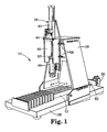
- Figure 1 is a perspective view of a welding system of the present invention.
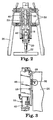
- Figure 2 is a front view of the welder of the welding system of Figure 1 with parts broken away.
- Figure 3 is a side view of the spring plunger of the welding system of Figure 1.
- Figure 4 is a schematic view of the welding system of Figure 1.
- the invention can provide an ultrasonic weld using either continuous welding, plunge welding, or a combination of both.
- the system can vary (also known as profile) and control the weld amplitude, weld force, table speed, table position, weld horn speed, and weld horn position simultaneously for a continuous or plunge weld. These parameters can be varied in any combination, in accordance with a preset profile, and in response to other external inputs.
- Figure 4 shows the relationship between the major system components of the welding system.
- the direction of travel of the part in the horizontal plane is along the X axis.
- the Y axis is perpendicular to the X axis in the horizontal plane.
- the Z axis is perpendicular to the X and Y axes in the vertical plane.
- the welding system 10 shown in Figures 1-4, includes a traversing table 12, a controller 14, and an adapter 48.
- the adapter 48 encloses a converter 18, and a booster 20, which is attached to a horn 22.
- the ultrasonic stack (converter 18, booster 20, and horn 22) is driven by an ultrasonic power supply 23.
- the system 10 precisely controls key process parameters for accurate positioning of the sonic horn during welding processes.
- the controller 14 allows a user to control the horn 22 and part velocity, horn (weld) force, horn and part position, and weld amplitude of the sonic energy vibrations to preset profiles or in response to part requirements.
- the controller 14 also allows the user to program trigger (enable or disable) the sonic energy as a function of horn force, horn or table position, time, or an external input such as temperature or frequency. This enables the welding of areas having different energy requirements, such as welding volumes, surface areas, and material thicknesses.
- Variable force in the Z direction can be achieved by using variable pneumatic force control (slow response) or varying the horn position using, for example, a stepper motor and drive mechanism, magnetics, piezoelectrics, lead screws, hydraulics, or combinations of these.
- the Z axis motion can be accomplished by moving an anvil (not shown) which can be mounted on the traversing table 12.
- Variable speed in the X, Y, and Z directions can be achieved by using variable pneumatic force control (slow response) or varying the position of the traversing table using a stepper motor and drive mechanism, magnetics, piezoelectrics, lead screws or hydraulics, or combinations of these.
- the amplitude is the easiest to change rapidly. Amplitude changes can be made electrically using commercially available welders. In many power supplies the amplitude can be varied by controlling the DC supply voltage within the power supply. Rapid changes of the weld speed and the weld force are more difficult to obtain than changes in weld amplitude.
- the system response be such that part speeds in the X-Y plane of 30 m/min (100 ft/min) can be used.
- Hydraulic, piezoelectric, magnetic systems, or combinations of these, can meet these requirements.
- the weld amplitude, displacement (horn-to-part position), weld speed, and weld force can vary as a function of the part position for continuous or scan welding, or as a function of time for plunge welding, to achieve a desired weld.
- the desired weld can have consistent or varying quality.
- the controller can be programmed using other external input signals to adjust automatically any or all weld parameters to obtain the desired weld level.
- Some controlling methods include measuring incoming product thickness and automatically adjusting; measuring and controlling thickness of the weld itself; measuring and controlling weld temperature during welding; and measuring part frequency and energy feedback. Design data for the part weld area can be input from 3D modeling techniques.
- FIGS 1-4 show an example of a system that has been made, but do not limit the scope of the invention to the specifications given.
- the horn 22 is an acoustical tool generally made of aluminum, titanium, or sintered steel that can resonate at sonic or ultrasonic frequencies when driven by a commercially available ultrasonic power supply 23.
- the horn 22 can weld ultrasonically or otherwise and can operate using continuous or plunge welding. (The horn 22 will be described as providing ultrasonic energy throughout this description.)
- a rotary or traversing table 12 can move relative to the horn 22 to weld continuous or intermittent webs or piece parts. Alternatively, the table could be stationary while moving the horn.
- the welding stack is mounted in the adapter 48 perpendicular to the traversing table 12 in the Z direction, imparts ultrasonic vibration to the parts to be welded, and moves in the Z direction.
- the converter 18 is a piezoelectric device which converts electrical energy into mechanical energy or vice versa.
- the booster 20 is a mechanical resonator, located between the converter 18 and the horn 22, which amplifies or deamplifies the amplitude of vibration.
- the horn 22 is mounted perpendicular to the traversing table 12 using a frame 26.
- the traversing table 12 moves along the X axis on a base plate 28 and is controlled using a table actuator 30, such as a hydraulic servo-controlled drive mechanism, such as an MTS Series 247 actuator, with a maximum stroke of 71.1 cm (28 in) to control table position from 0 cm (0 in)(home position) to 66.40 cm (26.14 in).
- An MTS TemposonicsTM displacement transducer serves as a position sensor 32 and provides an electrical feedback signal that indicates the actuator 30 position.
- the traversing table 12, to which an anvil can be attached is an electroless nickel plated, steel table having a regular grid pattern of mounting holes in the top surface.
- any anvil that is used is selected based on the size of the part being welded.
- Four linear bearings (not shown) are mounted under the table 12 and ride on rails rigidly attached to the base plate 28.
- the base plate 28 is a machined 10.2 cm (4 in) thick steel plate.
- the table 12 moves in the X-Y plane.
- Accelerometers 34, 36 are mounted on the table 12 and base plate 28 for stability and inertial force cancellation.
- the frame 26 is a steel plate weldment of box-type construction mounted to the sides of the base plate 28 using a pivot centered at the table top surface and along the Z axis.
- the frame 26, including the Z axis actuator 38, can be tilted ⁇ 5° along the X axis.
- the Z axis actuator 38 includes a Z axis hydraulic cylinder, attached to a actuator housing 40, a servo valve assembly 42, an accumulator 44, and a Z actuator mounting bracket 46 attached to the Z axis actuator 38.
- the Z axis hydraulic cylinder has a maximum stroke of about 25.4 cm (10 in) to control the Z axis position from about 26.09 cm (10.272 in)(fully retracted) to about 0.616 cm (0.241 in)(below the table).
- a linear variable differential transformer is mounted inside the Z axis cylinder piston rod to provide an electrical feedback signal that indicates its position.
- the servovalve 42 converts a control signal from the controller 14 to control the direction and amount of fluid flow to the Z axis actuator 38 to control the movement of the Z axis cylinder piston and rod.
- the ultrasonic horn 22, booster 20, and converter assembly 18 is mounted into an adapter 48 which rides on recirculating Z guide bearings and rails 50 mounted to the Z actuator mounting bracket.
- a load cell 52 is mounted between the adapter 48 and the Z axis cylinder piston rod. The load cell 52 provides the force feedback to the controller 14.
- An accelerometer 54 is also mounted on the adapter 48 for stability and inertial force cancellation.
- the hydraulic power supply 24 provides pressurized hydraulic fluid at 81.4 l/min (21 gal/min) and 20.7 MN (3000 psi) to the servovalve 42.
- a reservoir holds the hydraulic fluid
- a pump pressurizes the hydraulic fluid
- a motor runs the pump
- a heat exchanger cools the hydraulic fluid
- sensors monitor the level, pressure, and temperature of the hydraulic fluid, all in a known manner. Accumulators provide higher peak flow, as required.
- the Z actuator mounting bracket 46 can be adjusted ⁇ 12.7 cm (5 in) along the Z axis.
- a hand-retractable spring plunger 56 mounted on the back of the frame 26 facilitates positioning of the assembly by snapping into one of three detent positions (spaced 11.4 cm (4.5 in) apart) along the frame 26, although it can be positioned at any desired elevation.
- the Z actuator mounting bracket 46 can be adjusted up to ⁇ 2.54 cm ( ⁇ 1 in) and can be tilted up to ⁇ 2° along the Y axis. To move the Z actuator mounting bracket 46, the assembly is slid on the frame 26 until it is in the desired position, and then it is locked in position using clamps 58.
- the angle of the horn 22 relative to the table 12 top surface can be adjusted to improve alignment between the part and the horn 22.
- the welding stack enclosed in the adapter 48 can be adjusted in the Z direction up to 5° from perpendicular relative to the Y axis and 2° from perpendicular relative to the X axis. Rotation around the X axis is accomplished by pivoting the bracket on the frame 26 and around the Y axis is accomplished by tilting the frame 26.
- the Z axis actuator 38 can operate in a force mode with position limits or in a position mode with force limits.
- the actuator 38 can move this adapter 48 assembly rapidly to provide the set point weld force or position versus time values, table position in the X direction, or other input.
- the controller 14 uses a closed loop circuit to monitor and control the weld force on the part during welding.
- the same drive system which provides the part position output drives the variable force system, which profiles the force as desired, in the Z direction. This allows modifying position, force, or both, to achieve a uniform weld force across the weld zone to achieve a strong, uniform weld, regardless of non-uniform weld areas, part geometry, and non-random thicknesses. Alternatively, any desired weld intensity profile can be attained.
- the controller 14 can display the set point force and position profile and actual response profile after the weld.
- the system can operate at traversing speeds of 0 to 137 m/min (450 (ft/min).
- the traversing mechanism can accelerate the traversing table 12 from 0 to 61 m/min (200 ft/min) within 0.625 cm (0.25 in) or less of table travel at a maximum anvil weight of 667 N (150 lb) and a maximum weld drag force of 578 N (130 16).
- the hydraulic servo-controlled table actuator 30 provides fast response to a speed versus position profile of the table in the X direction.
- the position accuracy is measured by the position sensor 32.
- the position sensor 32 measures the table position in the X direction.
- the sensor 32 is used for feedback control of the speed and position of the table 12.
- the controller 14 can control movement of the traversing table 12 throughout the length of the travel in a predefined manner in a set point speed profile.
- the set point speed profile includes individual speed set points along the travel length of the table.
- the system allows programming of the weld variables at every 0.00254 cm (0.001 in) increment or every 1 millisecond.
- the controller 14 can provide a visual indication of the set point speed profile.
- the controller 14 has a feedback mechanism which provides feedback for closed loop control of the speed of the traversing table 12. The feedback is also used to collect real time data for a visual indication of the actual speed profile.
- a fast response drive mechanism allows the weld force to be continuously variable from 0 to 4448 N (1000 lb). With an identical specimen and identical program conditions, the weld force is repeatable within the following limits: 0 to 445 N ⁇ 13.5 N (100 lb ⁇ 3 lb), and 445 to 4448 N (100 to 1000 lb), ⁇ 3%.
- the weld force can be increased or decreased by a factor of at least 5 in 12.5 milliseconds or less.
- the welding system 10 can profile the Z axis in the position or force mode.
- the horn 22 When the weld part exerts an upward force on the horn 22 greater than the weld force set point value, the horn 22 "floats" at the set point force on the part, as long as the horn 22 is above the preset Z axis position.
- the resulting force errors are no more than 157.6 N for each cm/sec (90 lb for each in/sec) of disturbance, neglecting inertial effects of the ultrasonic stack and its mountings.
- Transducers measure the force and position of the horn 22 with respect to the part. It is used for a feedback control of force and position in the Z direction.
- the controller 14 corrects any deviations measured by the force and position transducer.
- the controller 14 can display the set point force and position profile and the actual response profile after the weld.
- An ultrasonic power supply 23 drives the welding stack at the desired frequency.
- An interface between the controller 14 and the ultrasonic power supply 23 provides a signal to the ultrasonic power supply 23 to profile the weld amplitude during welding.
- the vibration of the horn 22 can be measured and feedback control can regulate the amplitude to the desired set point profile.
- the controller 14 enters, stores, displays, plots, and retrieves set point data profiles and the actual response data profiles.
- the controlled set points and recorded measurements include table speed command, table speed feedback, X axis position command, X axis position feedback, horn weld amplitude profile, Z axis position command, Z axis position feedback, Z axis force command, Z axis force feedback, and other external inputs, including energy, power, and temperature.
- the controller 14 commands the force/position actuator, amplitude, and speed/position actuator.
- the controller 14 provides sufficient multiple set points to enter the desired profiles.
- the weld speed, weld force, Z position, and weld amplitude profiles can be created by locating the part at a given position and entering the desired weld speed, weld force, and weld amplitude set points to create the desired profiles.
- the controller 14 provides an amplitude output in the range of -10 to 10 volts DC. This controls the weld amplitude throughout the length of travel in a predefined manner in the form of a set point amplitude profile for continuous welding or throughout the weld cycle for plunge welding.
- the controller 14 provides and plots a variable amplitude profile as a function of time, position, or external input and can provide a visual indication of the set point amplitude profile.
- the welding system 10 can provide and plot a variable force, amplitude, and horn position profile as a function of time, or other external inputs, while the table remains stationary for plunge welding.
- the descent rate of the Z axis actuator is programmable from full acceleration down to 0.25 cm/sec (0.1 in/sec).
- a switch closure is actuated when a preset force from the load cell is sensed.
- Force adjustment is adjustable every millisecond during the weld cycle. The incremental force change occurs in ramp fashion, moving from one position to another with a defined slope.
- the force adjustments can be changed as a function of time or can be controlled by external inputs, such as a momentary pulse or switch closure.
- the speed at which the horn approaches the part can be adjusted according to a position versus time profile.
- an internal timer signal can be activated to determine the time that the system remains in the force versus time mode. After the elapsed time, the actuator retracts at a programmable rate.
- the weld duration can also be determined by horn position, weld velocity, weld force, weld time, or other external inputs such as power, energy, frequency, and temperature. Also, within a given cycle, multiple weld durations can be achieved.
- this invention profiles amplitude, force, and speed of the table according to the part design during scan welding.
- the amplitude is changed during welding by an external signal.
- the present invention does not measure amplitude and has no comparator in the loop to correct any deviation.
- the amplitude follows a set point profile during a weld. If amplitude deviates from the set point profile, then for the next weld, the force, speed of the table, or input voltage is changed to get the desired set point values.
- the present invention also profiles force, position, and speed changes during scan welding. The change of amplitude is linked to changes in force and speed or position of the part.
- U.S. -A- 5,199,630 maintains a constant amplitude, rather than changing the amplitude during welding, as the polymer changes its state.
- this invention increases or decreases force for both weld time or speed and position and hold time for scan and plunge welding modes.
- the apparatus can profile force, Z position, and amplitude as a function of time (plunge welding), and also can profile force, amplitude, weld position, and speed of the part for scan welding. All parameters (force, amplitude, position, and speed) are interrelated and will be changed in a decreasing or increasing manner depending on the part.
- the force change as a function of position is achieved in 12.5 milliseconds or less.
- the invention permits rapid parameter changes which are critical to high speed bonding.
Landscapes
- Engineering & Computer Science (AREA)
- Mechanical Engineering (AREA)
- Lining Or Joining Of Plastics Or The Like (AREA)
Abstract
Claims (4)
- Un procédé de soudage de pièces comprenant les étapes consistant à:amener en contact une pièce et un cornet (22) en communiquant entre la pièce et le cornet (22) un mouvement relatif généralement parallèle à une surface de travail du cornet (22),appliquer du cornet (22) à la pièce une énergie de haute fréquence,modifier au cours du soudage, en utilisant un réglage à rétroaction en temps réel, les paramètres de soudage, c'est-à-dire la force de soudure, la vitesse de soudure, l'amplitude de soudure, la position de la pièce, et la position du cornet, en fonction d'une ou plusieurs entrées externes préprogrammées ou mesurées, selon les besoins, y compris la température, la rapidité de soudure, la force, la position de la pièce, la fréquence, le volume de soudure et l'énergie de soudure, afin de souder ainsi des zones pour lesquelles les exigences d'énergie sont différentes, etajuster automatiquement en temps réel les paramètres de soudure en utilisant un réglage à rétroaction, en réponse aux entrées mesurées, afin d'obtenir le niveau de soudure souhaité,dans lequel l'étape de modification comprend des modifications de l'amplitude de soudure, de la force de soudure, de la position du cornet et de la vitesse de soudure afin de régler l'intensité de soudure sans exiger ni arrêts mécaniques, ni contrecames, ni zones de soudure sacrificielles.
- Le procédé selon la revendication 1, dans lequel l'étape d'ajustement comprend au moins l'une des étapes suivantes: mesurer l'épaisseur de la pièce entrante et ajuster, mesurer et régler automatiquement l'épaisseur de soudure; mesurer et régler la température de soudure pendant le soudage; mesurer la fréquence de pièce; mesurer l'énergie de soudure; et régler la qualité de soudure.
- Un appareil à souder de pièces comprenant:un cornet (22) à haute fréquence,un moyen (30) de communication d'un mouvement relatif entre le cornet (22) et la pièce à souder,un moyen (14) destiné à modifier au cours du soudage, en utilisant un réglage à rétroaction en temps réel, les paramètres de soudage, c'est-à-dire la force de soudure, la vitesse de soudure, l'amplitude de soudure, la position de la pièce, et la position du cornet, selon les besoins, afin de souder des zones à volumes, superficies et épaisseurs de matière de soudage différents, en fonction d'une ou plusieurs entrées externes préprogrammées ou mesurées, selon les besoins, y compris la température, la rapidité de soudure, la force, la position de la pièce, la fréquence, le volume de soudure et l'énergie de soudure, afin de souder ainsi des zones pour lesquelles les exigences d'énergie sont différentes, etun moyen (14) d'ajustement automatique qui utilise un réglage à rétroaction en temps réel des paramètres de soudure, en réponse aux entrées mesurées, afin d'obtenir le niveau de soudure souhaité,dans lequel le moyen de modification (14) modifie l'amplitude de soudure, la force de soudure, la position du cornet et la vitesse de soudure afin de régler l'intensité de soudure sans exiger ni arrêts mécaniques, ni contre-cames, ni zones de soudure sacrificielles.
- L'appareil selon la revendication 3, dans lequel le moyen d'ajustement comprend au moins l'une des capacités suivantes: mesurer l'épaisseur de la pièce entrante et ajuster, mesurer et régler automatiquement l'épaisseur de soudure; mesurer et régler la température de soudure pendant le soudage; mesurer la fréquence de pièce; mesurer l'énergie de soudure; et régler la qualité de soudure.
Applications Claiming Priority (3)
| Application Number | Priority Date | Filing Date | Title |
|---|---|---|---|
| US49448495A | 1995-06-26 | 1995-06-26 | |
| US494484 | 1995-06-26 | ||
| PCT/US1996/006905 WO1997001432A1 (fr) | 1995-06-26 | 1996-05-15 | Controleur de soudage |
Publications (2)
| Publication Number | Publication Date |
|---|---|
| EP0835178A1 EP0835178A1 (fr) | 1998-04-15 |
| EP0835178B1 true EP0835178B1 (fr) | 2001-08-16 |
Family
ID=23964683
Family Applications (1)
| Application Number | Title | Priority Date | Filing Date |
|---|---|---|---|
| EP19960915804 Expired - Lifetime EP0835178B1 (fr) | 1995-06-26 | 1996-05-15 | Controleur de soudage |
Country Status (4)
| Country | Link |
|---|---|
| EP (1) | EP0835178B1 (fr) |
| JP (1) | JPH11509487A (fr) |
| DE (1) | DE69614544T2 (fr) |
| WO (1) | WO1997001432A1 (fr) |
Families Citing this family (23)
| Publication number | Priority date | Publication date | Assignee | Title |
|---|---|---|---|---|
| DE19803638A1 (de) | 1998-02-02 | 1999-08-05 | Kuesters Eduard Maschf | Vorrichtung zum Bearbeiten einer Materialbahn mit Ultraschall |
| US6036796A (en) * | 1998-06-26 | 2000-03-14 | Branson Electronics | Closed-loop ultrasonic welding method and apparatus |
| JP2001048125A (ja) * | 1999-08-02 | 2001-02-20 | Furukawa Mfg Co Ltd | 包材の溶着温度コントロル方法及び装置 |
| DE10301433B4 (de) * | 2003-01-16 | 2008-05-29 | Fraunhofer-Gesellschaft zur Förderung der angewandten Forschung e.V. | Ultraschallschweißanlage und Verfahren zur Erfassung der Position von Sonotroden zu Bauteilaufnahmen |
| JP4203446B2 (ja) * | 2004-05-25 | 2009-01-07 | 富士フイルム株式会社 | テープリール用金属プレートのかしめ方法 |
| WO2006074116A1 (fr) * | 2005-01-03 | 2006-07-13 | 3M Innovative Properties Company | Lamelle elastique et procede de fabrication du lamelle |
| US8433433B2 (en) * | 2010-12-16 | 2013-04-30 | Lg Chem, Ltd. | System and method for determining whether an ultrasonic horn is aligned with an anvil |
| US9034129B2 (en) | 2011-01-13 | 2015-05-19 | Lg Chem, Ltd. | Ultrasonic welding system and method for forming a weld joint utilizing the ultrasonic welding system |
| DE102011076637A1 (de) * | 2011-05-27 | 2012-11-29 | Mahle International Gmbh | Verfahren zur Optimierung von Schweißnähten |
| US8640760B2 (en) | 2011-08-19 | 2014-02-04 | Lg Chem, Ltd. | Ultrasonic welding machine and method of aligning an ultrasonic welding horn relative to an anvil |
| US8695867B2 (en) | 2011-08-31 | 2014-04-15 | Lg Chem, Ltd. | Ultrasonic welding machine and method of assembling the ultrasonic welding machine |
| CN102529091B (zh) * | 2012-02-13 | 2014-05-07 | 浙江普莱得电器有限公司 | 一种冲压焊接机 |
| EP3204214B1 (fr) * | 2014-10-09 | 2024-12-18 | WoodWelding AG | Ancrage d'un élément de jonction dans un objet |
| US10213964B2 (en) * | 2015-05-08 | 2019-02-26 | The Boeing Company | Methods and apparatus for repairing composite materials |
| PL3807080T3 (pl) * | 2018-06-13 | 2025-07-21 | Dukane Ias, Llc | Sposoby określania grubości warstwy stopionej związanej z ustaloną wytrzymałością zgrzewu na podstawie korelacji pomiędzy nimi |
| DE102018132840A1 (de) * | 2018-12-19 | 2020-06-25 | Herrmann Ultraschalltechnik Gmbh & Co. Kg | Ultraschallschweißanlage mit formschlüssiger Verbindung |
| DE102018132839A1 (de) | 2018-12-19 | 2020-06-25 | Herrmann Ultraschalltechnik Gmbh & Co. Kg | Ultraschallschweißanlage mit Abstützelement |
| DE102018132838A1 (de) | 2018-12-19 | 2020-06-25 | Herrmann Ultraschalltechnik Gmbh & Co. Kg | Ultraschallschweißanlage mit Halterung |
| CN109702315B (zh) * | 2018-12-27 | 2024-05-03 | 东莞市鸿振超声波设备有限公司 | 一种利用位置与压力触发的超声波控制电路及焊接方法 |
| US20220143762A1 (en) * | 2020-11-11 | 2022-05-12 | Branson Ultrasonics Corporation | Dynamic mode work piece processing device |
| KR102833462B1 (ko) | 2021-10-21 | 2025-07-14 | 주식회사 엘지에너지솔루션 | 용접 압력 제어 시스템, 이를 이용하는 용접 압력 제어 방법 및 이를 이용하는 용접대상물 두께 측정방법 |
| DE102022115875A1 (de) | 2022-06-24 | 2024-01-04 | Herrmann Ultraschalltechnik Gmbh & Co. Kg | Bauteilgesteuertes Ultraschallschweißverfahren |
| DE102024108148A1 (de) | 2024-03-21 | 2025-09-25 | Herrmann Ultraschalltechnik Gmbh & Co. Kg | Grafisches Verfahren zur Optimierung von Prozessparametern |
Family Cites Families (7)
| Publication number | Priority date | Publication date | Assignee | Title |
|---|---|---|---|---|
| DE3313918A1 (de) | 1982-04-20 | 1983-10-27 | Basf Ag, 6700 Ludwigshafen | Verfahren zur steuerung und regelung der beim fuegen von thermoplasten mittels ultraschall benoetigten elektrischen leistung |
| DD281038A1 (de) | 1989-03-29 | 1990-07-25 | Koepenick Funkwerk Veb | Verfahren zur steuerung und regelung des prozesskraftverlaufs bei ultraschallanwendungen |
| US4973876A (en) | 1989-09-20 | 1990-11-27 | Branson Ultrasonics Corporation | Ultrasonic power supply |
| EP0421019B1 (fr) | 1989-10-06 | 1994-01-19 | Siemens Aktiengesellschaft | Méthode et dispositif de jointure d'éléments en matière plastique par ultrasons |
| EP0498936B1 (fr) | 1991-02-15 | 1995-01-25 | Esec Sa | Procédé et dispositif de mesure de l'amplitude d'oscillation d'un transducteur d'énergie |
| DE4206584C2 (de) | 1992-03-03 | 1994-03-10 | Fraunhofer Ges Forschung | Vorrichtung und Verfahren zum Verbinden zweier Bauteile mittels Ultraschall |
| SE501372C2 (sv) | 1993-06-17 | 1995-01-30 | Moelnlycke Ab | Förfarande och anordning för att vid ultraljudssvetsning reglera aggregatets effekt |
-
1996
- 1996-05-15 WO PCT/US1996/006905 patent/WO1997001432A1/fr not_active Ceased
- 1996-05-15 JP JP50439597A patent/JPH11509487A/ja not_active Withdrawn
- 1996-05-15 EP EP19960915804 patent/EP0835178B1/fr not_active Expired - Lifetime
- 1996-05-15 DE DE69614544T patent/DE69614544T2/de not_active Expired - Fee Related
Also Published As
| Publication number | Publication date |
|---|---|
| JPH11509487A (ja) | 1999-08-24 |
| EP0835178A1 (fr) | 1998-04-15 |
| DE69614544D1 (de) | 2001-09-20 |
| WO1997001432A1 (fr) | 1997-01-16 |
| DE69614544T2 (de) | 2002-04-04 |
Similar Documents
| Publication | Publication Date | Title |
|---|---|---|
| EP0835178B1 (fr) | Controleur de soudage | |
| Stokes | Vibration welding of thermoplastics. Part I: Phenomenology of the welding process | |
| US4844320A (en) | Control system and method for vibration welding | |
| CN102421584B (zh) | 超声波焊接装置和焊接材料卷的方法 | |
| CA2152282C (fr) | Tete de soudage a reaction rapide | |
| US9550323B2 (en) | Systems and methods for adaptive process control using a target kinematics profile in welding together multiple polymeric workpieces | |
| US4313778A (en) | Ultrasonic seaming apparatus | |
| US20120111475A1 (en) | Device and method for processing a packing material using ultrasound | |
| US20160158877A1 (en) | Dual ultrasonic welder | |
| CN109702313B (zh) | 双凸轮伺服焊接接线器 | |
| JP3963918B2 (ja) | 超音波溶着装置 | |
| EP1301331B1 (fr) | Dispositif de commande d'energie pour une soudeuse a vibration | |
| JP2006507165A (ja) | ニップ型加工における加工物上のポイントサイトへの圧縮荷重をシミュレーションするためのプレス | |
| US20140338814A1 (en) | Vibration welders with high frequency vibration, position motion control, and delayed weld motion | |
| JP7789431B2 (ja) | 材料の超音波圧密 | |
| WO2007130599A9 (fr) | Système adaptatif de soudage acoustique continu pour matériaux incompatibles | |
| EP2457727A2 (fr) | Appareil et procédé de traitement ultrasonique de stratifié | |
| US20020148878A1 (en) | Method and apparatus for linear vibration welding | |
| JP2021515706A (ja) | コンプライアンス弾性部材および重量補償弾性部材を有するサーボ弾性アクチュエータシステムを備えるワークピース加工装置 | |
| KR100602200B1 (ko) | 하이브리드 용접 제어장치 | |
| EP4324586B1 (fr) | Système de soudage par sonication | |
| US20100071194A1 (en) | Ultrasonic system and method for affixing a screen sub-assembly to a plate | |
| CN112192849A (zh) | 一种用于弧面柔性产品的超声波焊接工装及焊接方法 | |
| CN112172160A (zh) | 一种超声波焊接监测装置 | |
| JP6947402B2 (ja) | 高周波溶着装置及び高周波溶着方法 |
Legal Events
| Date | Code | Title | Description |
|---|---|---|---|
| PUAI | Public reference made under article 153(3) epc to a published international application that has entered the european phase |
Free format text: ORIGINAL CODE: 0009012 |
|
| 17P | Request for examination filed |
Effective date: 19971127 |
|
| AK | Designated contracting states |
Kind code of ref document: A1 Designated state(s): DE FR GB NL |
|
| 17Q | First examination report despatched |
Effective date: 19981110 |
|
| GRAG | Despatch of communication of intention to grant |
Free format text: ORIGINAL CODE: EPIDOS AGRA |
|
| GRAG | Despatch of communication of intention to grant |
Free format text: ORIGINAL CODE: EPIDOS AGRA |
|
| GRAH | Despatch of communication of intention to grant a patent |
Free format text: ORIGINAL CODE: EPIDOS IGRA |
|
| GRAH | Despatch of communication of intention to grant a patent |
Free format text: ORIGINAL CODE: EPIDOS IGRA |
|
| GRAA | (expected) grant |
Free format text: ORIGINAL CODE: 0009210 |
|
| AK | Designated contracting states |
Kind code of ref document: B1 Designated state(s): DE FR GB NL |
|
| REF | Corresponds to: |
Ref document number: 69614544 Country of ref document: DE Date of ref document: 20010920 |
|
| ET | Fr: translation filed | ||
| REG | Reference to a national code |
Ref country code: GB Ref legal event code: IF02 |
|
| PLBE | No opposition filed within time limit |
Free format text: ORIGINAL CODE: 0009261 |
|
| STAA | Information on the status of an ep patent application or granted ep patent |
Free format text: STATUS: NO OPPOSITION FILED WITHIN TIME LIMIT |
|
| 26N | No opposition filed | ||
| PGFP | Annual fee paid to national office [announced via postgrant information from national office to epo] |
Ref country code: NL Payment date: 20070524 Year of fee payment: 12 |
|
| PG25 | Lapsed in a contracting state [announced via postgrant information from national office to epo] |
Ref country code: NL Free format text: LAPSE BECAUSE OF NON-PAYMENT OF DUE FEES Effective date: 20081201 |
|
| PGFP | Annual fee paid to national office [announced via postgrant information from national office to epo] |
Ref country code: DE Payment date: 20090528 Year of fee payment: 14 |
|
| REG | Reference to a national code |
Ref country code: FR Ref legal event code: ST Effective date: 20100129 |
|
| PG25 | Lapsed in a contracting state [announced via postgrant information from national office to epo] |
Ref country code: FR Free format text: LAPSE BECAUSE OF NON-PAYMENT OF DUE FEES Effective date: 20090602 |
|
| PGFP | Annual fee paid to national office [announced via postgrant information from national office to epo] |
Ref country code: FR Payment date: 20080519 Year of fee payment: 13 |
|
| PGFP | Annual fee paid to national office [announced via postgrant information from national office to epo] |
Ref country code: GB Payment date: 20100401 Year of fee payment: 15 |
|
| PG25 | Lapsed in a contracting state [announced via postgrant information from national office to epo] |
Ref country code: DE Free format text: LAPSE BECAUSE OF NON-PAYMENT OF DUE FEES Effective date: 20101201 |
|
| GBPC | Gb: european patent ceased through non-payment of renewal fee |
Effective date: 20110515 |
|
| PG25 | Lapsed in a contracting state [announced via postgrant information from national office to epo] |
Ref country code: GB Free format text: LAPSE BECAUSE OF NON-PAYMENT OF DUE FEES Effective date: 20110515 |