EP0835371B1 - Stirlingmotor-getriebe - Google Patents
Stirlingmotor-getriebe Download PDFInfo
- Publication number
- EP0835371B1 EP0835371B1 EP97921668A EP97921668A EP0835371B1 EP 0835371 B1 EP0835371 B1 EP 0835371B1 EP 97921668 A EP97921668 A EP 97921668A EP 97921668 A EP97921668 A EP 97921668A EP 0835371 B1 EP0835371 B1 EP 0835371B1
- Authority
- EP
- European Patent Office
- Prior art keywords
- piston
- stirling engine
- connecting rod
- engine according
- working
- Prior art date
- Legal status (The legal status is an assumption and is not a legal conclusion. Google has not performed a legal analysis and makes no representation as to the accuracy of the status listed.)
- Expired - Lifetime
Links
- 238000001816 cooling Methods 0.000 claims abstract description 4
- 238000010438 heat treatment Methods 0.000 claims abstract description 4
- 230000008878 coupling Effects 0.000 claims 3
- 238000010168 coupling process Methods 0.000 claims 3
- 238000005859 coupling reaction Methods 0.000 claims 3
- 238000006073 displacement reaction Methods 0.000 description 10
- 239000007789 gas Substances 0.000 description 4
- 230000005540 biological transmission Effects 0.000 description 3
- 238000010586 diagram Methods 0.000 description 2
- 239000001307 helium Substances 0.000 description 2
- 229910052734 helium Inorganic materials 0.000 description 2
- SWQJXJOGLNCZEY-UHFFFAOYSA-N helium atom Chemical compound [He] SWQJXJOGLNCZEY-UHFFFAOYSA-N 0.000 description 2
- 238000010276 construction Methods 0.000 description 1
- 238000005516 engineering process Methods 0.000 description 1
- 238000005457 optimization Methods 0.000 description 1
- 230000002265 prevention Effects 0.000 description 1
- 230000001172 regenerating effect Effects 0.000 description 1
- 230000003068 static effect Effects 0.000 description 1
Images


Classifications
-
- F—MECHANICAL ENGINEERING; LIGHTING; HEATING; WEAPONS; BLASTING
- F16—ENGINEERING ELEMENTS AND UNITS; GENERAL MEASURES FOR PRODUCING AND MAINTAINING EFFECTIVE FUNCTIONING OF MACHINES OR INSTALLATIONS; THERMAL INSULATION IN GENERAL
- F16H—GEARING
- F16H21/00—Gearings comprising primarily only links or levers, with or without slides
- F16H21/10—Gearings comprising primarily only links or levers, with or without slides all movement being in, or parallel to, a single plane
- F16H21/16—Gearings comprising primarily only links or levers, with or without slides all movement being in, or parallel to, a single plane for interconverting rotary motion and reciprocating motion
- F16H21/18—Crank gearings; Eccentric gearings
- F16H21/22—Crank gearings; Eccentric gearings with one connecting-rod and one guided slide to each crank or eccentric
- F16H21/32—Crank gearings; Eccentric gearings with one connecting-rod and one guided slide to each crank or eccentric with additional members comprising only pivoted links or arms
-
- F—MECHANICAL ENGINEERING; LIGHTING; HEATING; WEAPONS; BLASTING
- F02—COMBUSTION ENGINES; HOT-GAS OR COMBUSTION-PRODUCT ENGINE PLANTS
- F02G—HOT GAS OR COMBUSTION-PRODUCT POSITIVE-DISPLACEMENT ENGINE PLANTS; USE OF WASTE HEAT OF COMBUSTION ENGINES; NOT OTHERWISE PROVIDED FOR
- F02G1/00—Hot gas positive-displacement engine plants
- F02G1/04—Hot gas positive-displacement engine plants of closed-cycle type
- F02G1/043—Hot gas positive-displacement engine plants of closed-cycle type the engine being operated by expansion and contraction of a mass of working gas which is heated and cooled in one of a plurality of constantly communicating expansible chambers, e.g. Stirling cycle type engines
- F02G1/044—Hot gas positive-displacement engine plants of closed-cycle type the engine being operated by expansion and contraction of a mass of working gas which is heated and cooled in one of a plurality of constantly communicating expansible chambers, e.g. Stirling cycle type engines having at least two working members, e.g. pistons, delivering power output
-
- F—MECHANICAL ENGINEERING; LIGHTING; HEATING; WEAPONS; BLASTING
- F02—COMBUSTION ENGINES; HOT-GAS OR COMBUSTION-PRODUCT ENGINE PLANTS
- F02G—HOT GAS OR COMBUSTION-PRODUCT POSITIVE-DISPLACEMENT ENGINE PLANTS; USE OF WASTE HEAT OF COMBUSTION ENGINES; NOT OTHERWISE PROVIDED FOR
- F02G2243/00—Stirling type engines having closed regenerative thermodynamic cycles with flow controlled by volume changes
- F02G2243/02—Stirling type engines having closed regenerative thermodynamic cycles with flow controlled by volume changes having pistons and displacers in the same cylinder
-
- F—MECHANICAL ENGINEERING; LIGHTING; HEATING; WEAPONS; BLASTING
- F02—COMBUSTION ENGINES; HOT-GAS OR COMBUSTION-PRODUCT ENGINE PLANTS
- F02G—HOT GAS OR COMBUSTION-PRODUCT POSITIVE-DISPLACEMENT ENGINE PLANTS; USE OF WASTE HEAT OF COMBUSTION ENGINES; NOT OTHERWISE PROVIDED FOR
- F02G2270/00—Constructional features
- F02G2270/50—Crosshead guiding pistons
Definitions
- the invention is directed to a Stirling engine with a heated cylinder head and with a cooler for heating or cooling a working medium as well as with a Displacer and a working piston, which is effectively an output axis apply.
- Stirling engines are known in a variety of designs, here is an example of DE-40 16 238-C2 as a combination of such an engine with a boiler system.
- the basic principle of such a Stirling engine is that a constant gas volume (today mostly helium used) within the Stirling engine of two pistons is pushed back and forth. On the one hand it will Helium through the flame of a gas burner in the heater tube heated and on the other hand by a cooler cooled. In between is a regenerator, the the gas on its way from the hot to the cold side withdrawn and fed back in the event of backflows.
- a gear connects the two pistons so that power e.g. about Generators can be removed.
- the pistons are there alternately moved in parallel or against each other, whereby the Gas is compressed by one piston and after heat is applied is relaxed again by the other.
- the object of the invention is therefore to solve these problem points, i.e. it is intended for adequate balancing as well as static prevention over-determined stock and achieving minimization of lateral forces.
- the particular advantage of the double eccentric constructed in this way according to the invention is that the bearing points of attack of the two connecting rods in the double eccentric according to the invention practically lie in each other, since they are both in the cylinder axis plane are arranged. So there is no balancing in the Shaft axis plane more necessary.
- the invention ensures that a transmission technology very compact design is possible. Also can be the occurring, partly opposing loads compensate for the introduction into the double eccentric disc more easily.
- An expedient embodiment of the invention consists in that the outside of the double eccentric is the working piston rod and an eccentric hole in the double eccentric disc is assigned to the displacement piston connecting rod. This also leads to a compact design because it is possible is, the bearing of the eccentric piston disc comparatively to get close to each other.
- the invention also provides that the double eccentric supporting stub shaft of the output shaft in the gearbox a coaxial, fixed counter bearing is assigned to the an eccentric counter mass disc, which in turn carries the eccentric axis of the displacement piston connecting rod via a sliding block connected is.
- the free end of the piston rod can be used rotatable the link lever and at least one working piston rod be assigned, as is the invention provides.
- the double eccentric disc at least a co-rotating counterweight is assigned, whereby a special feature of the invention in a further embodiment is that the double eccentric oscillating blind piston is assigned, whose axis in is at right angles to the main piston axis.
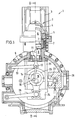
- the Stirling engine generally designated 1, consists of essentially from a heatable cylinder head 2 with a Variety of heater tubes 3, the one hand in one Expansion space 4 and on the other hand in a regenerator 5 open, oscillating in the expansion space 4 Displacement piston 6 is located. Closes at the regenerator 5 a cooler 7 for cooling the working medium, the a working piston designated 8, which in Fig. 1 is shown in the top dead center position.
- the displacer piston 6 has a displacer piston rod 11 on, the free end 12 with a housing side pivoted mounted pivot lever 13 and an eccentric lever 14 is connected on the other hand, this eccentric lever 14th again an eccentric bore 15 generally with 16 designated double eccentric is assigned.
- This double eccentric 16 is, as is particularly so from Fig. 2, arranged in a coaxial to the generator Stub shaft 17 stored and indirectly in one coaxial counter bearing 18.
- This indirect bearing takes place such that an eccentric counter-mass disk in the counter bearing 18 19 is mounted, which is eccentric to her Sliding block 20 arranged in the counter bearing 18 carries, which in turn the rotary shaft 21 for free end of the eccentric lever 14 carries, which in turn in the eccentric disc 16 is mounted eccentrically in the bore 15 is.
- the eccentric disk 16 is in the example shown on its side facing the output 17 with a Counterweight 29 equipped.
- the free end is still rotatable with a link lever 26 connected, which in turn like the articulation lever 13 for the Displacement piston is pivotally mounted in the housing 9, such as this results in particular from FIG. 1.
- Both link levers 13 and 26 essentially provide one linear movement of the system elements.
- a further piston rod 27 for a 90 ° to the axis of movement of the displacement piston or working piston positioned blind piston 28 is provided as a balancing element.
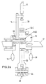
- FIG. 2a The basic structure of the transmission is shown schematically in FIG. 2a approximately shown in FIG. 2 to illustrate that the two designated EX I and EX II eccentricities in the double eccentric 16 practically in a plane of the piston axis, designated 30 there.
- FIGS. 1 and 2 are a basic in Fig. 3 Functional diagram of the invention shown with opposite Fig. 1 a rotation of about 180 °.
- the described embodiment of the invention still change in many ways without the To leave basic ideas. So the invention is not on a special way of designing the heater or cooler part of the Stirling engine, also not limited to a certain type of downforce.
Landscapes
- Engineering & Computer Science (AREA)
- General Engineering & Computer Science (AREA)
- Mechanical Engineering (AREA)
- Chemical & Material Sciences (AREA)
- Combustion & Propulsion (AREA)
- Transmission Devices (AREA)
- Lubrication Of Internal Combustion Engines (AREA)
- Peptides Or Proteins (AREA)
- Pistons, Piston Rings, And Cylinders (AREA)
- General Details Of Gearings (AREA)
- Pharmaceuticals Containing Other Organic And Inorganic Compounds (AREA)
- Magnetic Bearings And Hydrostatic Bearings (AREA)
Description
- Fig. 1
- die Seitenansicht eines erfindungsgemäßen Stirlingmotors mit teilweise geschnittenem Getriebe,
- Fig. 2
- in gleicher Darstellung eine Schnittansicht etwa gemäß Linie II-II in Fig. 1,
- Fig. 2a
- eine Schemazeichnung der Fig. 2 sowie in
- Fig. 3
- ein Prinzipbild des Stirlingmotors mit Getriebe.
Claims (8)
- Stirlingmotor (1) mit einem beheizbaren Zylinderkopf (2) und mit einem Kühler (7) zum Erhitzen bzw. Kühlen eines Arbeitsmediums sowie mit einem Verdränger- (6) und einem Arbeitskolben (8), die wirkmäßig eine Abtriebsachse (22) beaufschlagen,
dadurch gekennzeichnet, daß die Abtriebsachse (22) mit einer Doppelexzenterscheibe (16) ausgerüstet ist, an der zum einen das Arbeitskolbenpleuel (23) und zum anderen das Verdrängerkolbenpleuel (14) angreifen, wobei beide Exzentrizitäten in der Ebene der Kolbenachse liegen. - Stirlingmotor nach Anspruch 1,
dadurch gekennzeichnet, daß die Außenseite der Doppelexzenterscheibe (16) dem Arbeitskolbenpleuel (23) und eine exzentrische Bohrung (15) in der Doppelexzenterscheibe (16) dem Verdrängerkolbenpleuel (14) zugeordnet ist. - Stirlingmotor nach Anspruch 1 oder 2,
dadurch gekennzeichnet, daß dem den Doppelexzenter (16) tragenden Wellenstumpf (17) der Abtriebsachse (22) im Getriebegehäuse (9) ein koaxiales, ortsfestes Gegenlager (18) zugeordnet ist, das eine exzentrische Gegenmassenscheibe (19) trägt, die ihrerseits über einen Kulissenstein (20) mit der Exzenterachse (21) des Verdrängerkolbenpleuels (14) verbunden ist. - Stirlingmotor nach einem der vorangehenden Ansprüche,
dadurch gekennzeichnet, daß das freie Ende des Arbeitskolbenpleuels (23) drehbar den Anlenkhebel (26) und mindestens einer Arbeitskolbenstange (25) zugeordnet ist. - Stirlingmotor nach Anspruch 4,
dadurch gekennzeichnet, daß das freie Ende des Arbeitskolbenpleuels (23) koaxial das Lager eines schwenkbaren Anlenkhebels (26) trägt, dessen zweiter schwenkbarer Anlenkpunkt am Getriebegehäuse (9) vorgesehen ist. - Stirlingmotor nach einem der vorangehenden Ansprüche,
dadurch gekennzeichnet, daß der Doppelexzenterscheibe (16) ein mitrotierendes Gegengewicht (19 und/oder 29) zugeordnet ist. - Stirlingmotor nach einem der vorangehenden Ansprüche,
dadurch gekennzeichnet, daß der Doppelexzenterscheibe (16) ein oszillierender Blindkolben (28) zugeordnet ist, dessen Achse im rechten Winkel zur Hauptkolbenachse steht. - Stirlingmotor nach einem der vorangehenden Ansprüche, gekennzeichnet durch
eine auf einer Konsole verschraubbaren Führungsbuchse für eine Linearführung der Verdrängerkolbenstange (11).
Applications Claiming Priority (3)
| Application Number | Priority Date | Filing Date | Title |
|---|---|---|---|
| DE19616256A DE19616256A1 (de) | 1996-04-24 | 1996-04-24 | Stirlingmotor-Getriebe |
| DE19616256 | 1996-04-24 | ||
| PCT/EP1997/001978 WO1997040269A1 (de) | 1996-04-24 | 1997-04-19 | Stirlingmotor-getriebe |
Publications (2)
| Publication Number | Publication Date |
|---|---|
| EP0835371A1 EP0835371A1 (de) | 1998-04-15 |
| EP0835371B1 true EP0835371B1 (de) | 2002-03-20 |
Family
ID=7792239
Family Applications (1)
| Application Number | Title | Priority Date | Filing Date |
|---|---|---|---|
| EP97921668A Expired - Lifetime EP0835371B1 (de) | 1996-04-24 | 1997-04-19 | Stirlingmotor-getriebe |
Country Status (8)
| Country | Link |
|---|---|
| EP (1) | EP0835371B1 (de) |
| AT (1) | ATE214785T1 (de) |
| AU (1) | AU2765897A (de) |
| DE (2) | DE19616256A1 (de) |
| DK (1) | DK0835371T3 (de) |
| ES (1) | ES2175402T3 (de) |
| PT (1) | PT835371E (de) |
| WO (1) | WO1997040269A1 (de) |
Families Citing this family (3)
| Publication number | Priority date | Publication date | Assignee | Title |
|---|---|---|---|---|
| EP1126153A3 (de) | 2000-02-16 | 2002-10-23 | Josef Ing. Frauscher | Stirlingmaschine |
| DE102009023024A1 (de) | 2009-05-28 | 2010-12-09 | Schliebe, Günther | Stirlingmotoranordnung |
| CN119573273A (zh) * | 2024-12-16 | 2025-03-07 | 安徽光智科技有限公司 | 一种斯特林制冷机 |
Family Cites Families (7)
| Publication number | Priority date | Publication date | Assignee | Title |
|---|---|---|---|---|
| US2943453A (en) * | 1954-01-22 | 1960-07-05 | Philips Corp | Gaseous medium leakage prevention arrangement for a hot-gas reciprocating machine |
| US4248050A (en) * | 1980-01-22 | 1981-02-03 | The United States Of America As Represented By The Secretary Of The Army | Double-yoke balanced compressor |
| JPS58128441A (ja) * | 1982-01-26 | 1983-08-01 | Mitsubishi Electric Corp | スタ−リングエンジンのピストン駆動機構 |
| US4546663A (en) * | 1983-06-21 | 1985-10-15 | Sunpower, Inc. | Drive linkage for Stirling cycle and other machines |
| US4550571A (en) * | 1983-12-28 | 1985-11-05 | Helix Technology Corporation | Balanced integral Stirling cryogenic refrigerator |
| US4553392A (en) * | 1984-12-12 | 1985-11-19 | Stirling Technology, Inc. | Self pressurizing, crank-type Stirling engine having reduced loading of displacer drive linkages |
| DE3723950A1 (de) * | 1987-02-03 | 1988-08-11 | Helmut Prof Dr Krauch | Regenerative waermemaschine mit einem hypozykloidischen exzenter-kurbelgetriebe |
-
1996
- 1996-04-24 DE DE19616256A patent/DE19616256A1/de not_active Withdrawn
-
1997
- 1997-04-19 DE DE59706659T patent/DE59706659D1/de not_active Expired - Fee Related
- 1997-04-19 PT PT97921668T patent/PT835371E/pt unknown
- 1997-04-19 AU AU27658/97A patent/AU2765897A/en not_active Abandoned
- 1997-04-19 AT AT97921668T patent/ATE214785T1/de not_active IP Right Cessation
- 1997-04-19 EP EP97921668A patent/EP0835371B1/de not_active Expired - Lifetime
- 1997-04-19 WO PCT/EP1997/001978 patent/WO1997040269A1/de not_active Ceased
- 1997-04-19 ES ES97921668T patent/ES2175402T3/es not_active Expired - Lifetime
- 1997-04-19 DK DK97921668T patent/DK0835371T3/da active
Also Published As
| Publication number | Publication date |
|---|---|
| EP0835371A1 (de) | 1998-04-15 |
| PT835371E (pt) | 2002-09-30 |
| ATE214785T1 (de) | 2002-04-15 |
| DK0835371T3 (da) | 2002-07-01 |
| DE59706659D1 (de) | 2002-04-25 |
| AU2765897A (en) | 1997-11-12 |
| ES2175402T3 (es) | 2002-11-16 |
| WO1997040269A1 (de) | 1997-10-30 |
| DE19616256A1 (de) | 1997-11-20 |
Similar Documents
| Publication | Publication Date | Title |
|---|---|---|
| DE69733403T2 (de) | Hin-und hergehende maschine | |
| DE10051271B4 (de) | In ihrem Verdichtungsverhältnis einstellbare Kolbenbrennkraftmaschine mit integriertem Verstellaktuator | |
| EP0809749B1 (de) | Hubkolbenmaschine mit in kurbelwellenrichtung in einem maschinengehäuse benachbarten zylindern | |
| DE3506061A1 (de) | Taumelscheibenverdichter mit einer vorrichtung zur einstellung der leistung | |
| EP0975839B1 (de) | Stampfgerät zur bodenverdichtung | |
| DE2639260C3 (de) | Mehrzylindrige Hubkolben-Brennkraftmaschine | |
| EP0422338B1 (de) | Hydraulischer Schwingungsdämpfer | |
| EP0607154B1 (de) | Energiewandler nach dem prinzip des heissluftmotors | |
| DE10055753A1 (de) | Hydrostatische Axialkolbenmaschine in Schrägscheibenbauweise | |
| DE69524783T2 (de) | Neigungswinkelstellvorrichtung für eine taumelscheibenpumpe | |
| EP0835371B1 (de) | Stirlingmotor-getriebe | |
| EP1361356A2 (de) | Einrichtung zum Verlagern des Zylinderblocks und -kopfs gegenüber dem Kurbelgehäuse | |
| DE3723950A1 (de) | Regenerative waermemaschine mit einem hypozykloidischen exzenter-kurbelgetriebe | |
| DE3433510A1 (de) | Gleitstein fuer eine mit einer kurbelwelle zusammenwirkenden kurbelschleife, insbesondere fuer eine brennkraftmaschine mit mindestens einem zylinder | |
| DE4305133C2 (de) | Getriebe für Doppelschneckenextruder | |
| DE2659958B1 (de) | Vorrichtung zur Umwandlung einer hin- und hergehenden Bewegung in eine Drehbewegung | |
| DE2419581C2 (de) | Kolbenmaschine mit einer Ausgleichsmasse | |
| DE29614589U1 (de) | Hubkolbenmaschine mit veränderbar einstellbarem Massenausgleich | |
| DE3232974C2 (de) | Triebwerk zum Umwandeln von Rotationsbewegung in lineare Bewegung | |
| CH691449A5 (de) | Presse. | |
| EP2503195B1 (de) | Speisedruckbegrenzungsventil für ein hydrostatisches Getriebe | |
| DE4445131C2 (de) | Kurbelgetriebe, insbesondere für Verbrennungsmotoren | |
| DE2639960A1 (de) | Kolben-linear-stellantrieb zur uebertragung von drehbewegungen | |
| DE3604254A1 (de) | Kurbelgetriebe-formsystem | |
| EP0272522A1 (de) | Kurbeltrieb, insbesondere für Hubkolbenmotoren |
Legal Events
| Date | Code | Title | Description |
|---|---|---|---|
| PUAI | Public reference made under article 153(3) epc to a published international application that has entered the european phase |
Free format text: ORIGINAL CODE: 0009012 |
|
| AK | Designated contracting states |
Kind code of ref document: A1 Designated state(s): AT CH DE DK ES FI FR GB GR IE IT LI NL PT SE |
|
| 17P | Request for examination filed |
Effective date: 19980402 |
|
| RAP1 | Party data changed (applicant data changed or rights of an application transferred) |
Owner name: SIPRA PATENTENTWICKLUNGS- UND BETEILIGUNGSGESELLSC |
|
| GRAG | Despatch of communication of intention to grant |
Free format text: ORIGINAL CODE: EPIDOS AGRA |
|
| 17Q | First examination report despatched |
Effective date: 20010410 |
|
| GRAG | Despatch of communication of intention to grant |
Free format text: ORIGINAL CODE: EPIDOS AGRA |
|
| GRAH | Despatch of communication of intention to grant a patent |
Free format text: ORIGINAL CODE: EPIDOS IGRA |
|
| GRAH | Despatch of communication of intention to grant a patent |
Free format text: ORIGINAL CODE: EPIDOS IGRA |
|
| REG | Reference to a national code |
Ref country code: GB Ref legal event code: IF02 |
|
| GRAA | (expected) grant |
Free format text: ORIGINAL CODE: 0009210 |
|
| RAP1 | Party data changed (applicant data changed or rights of an application transferred) |
Owner name: SIPRA PATENTENTWICKLUNGS- UND BETEILIGUNGSGESELLSC |
|
| AK | Designated contracting states |
Kind code of ref document: B1 Designated state(s): AT CH DE DK ES FI FR GB GR IE IT LI NL PT SE |
|
| REF | Corresponds to: |
Ref document number: 214785 Country of ref document: AT Date of ref document: 20020415 Kind code of ref document: T |
|
| REG | Reference to a national code |
Ref country code: CH Ref legal event code: NV Representative=s name: E. BLUM & CO. PATENTANWAELTE Ref country code: CH Ref legal event code: EP |
|
| REF | Corresponds to: |
Ref document number: 59706659 Country of ref document: DE Date of ref document: 20020425 |
|
| ET | Fr: translation filed | ||
| GBT | Gb: translation of ep patent filed (gb section 77(6)(a)/1977) |
Effective date: 20020524 |
|
| REG | Reference to a national code |
Ref country code: DK Ref legal event code: T3 |
|
| REG | Reference to a national code |
Ref country code: GR Ref legal event code: EP Ref document number: 20020402057 Country of ref document: GR |
|
| REG | Reference to a national code |
Ref country code: PT Ref legal event code: SC4A Free format text: AVAILABILITY OF NATIONAL TRANSLATION Effective date: 20020620 |
|
| REG | Reference to a national code |
Ref country code: ES Ref legal event code: FG2A Ref document number: 2175402 Country of ref document: ES Kind code of ref document: T3 |
|
| PLBE | No opposition filed within time limit |
Free format text: ORIGINAL CODE: 0009261 |
|
| STAA | Information on the status of an ep patent application or granted ep patent |
Free format text: STATUS: NO OPPOSITION FILED WITHIN TIME LIMIT |
|
| 26N | No opposition filed |
Effective date: 20021223 |
|
| PGFP | Annual fee paid to national office [announced via postgrant information from national office to epo] |
Ref country code: NL Payment date: 20070403 Year of fee payment: 11 |
|
| PGFP | Annual fee paid to national office [announced via postgrant information from national office to epo] |
Ref country code: SE Payment date: 20070404 Year of fee payment: 11 |
|
| PGFP | Annual fee paid to national office [announced via postgrant information from national office to epo] |
Ref country code: IE Payment date: 20070412 Year of fee payment: 11 Ref country code: AT Payment date: 20070412 Year of fee payment: 11 |
|
| PGFP | Annual fee paid to national office [announced via postgrant information from national office to epo] |
Ref country code: FI Payment date: 20070413 Year of fee payment: 11 Ref country code: PT Payment date: 20070413 Year of fee payment: 11 Ref country code: CH Payment date: 20070413 Year of fee payment: 11 |
|
| PGFP | Annual fee paid to national office [announced via postgrant information from national office to epo] |
Ref country code: DK Payment date: 20070416 Year of fee payment: 11 |
|
| PGFP | Annual fee paid to national office [announced via postgrant information from national office to epo] |
Ref country code: ES Payment date: 20070521 Year of fee payment: 11 |
|
| PGFP | Annual fee paid to national office [announced via postgrant information from national office to epo] |
Ref country code: DE Payment date: 20070615 Year of fee payment: 11 |
|
| REG | Reference to a national code |
Ref country code: CH Ref legal event code: PFA Owner name: SIPRA PATENTENTWICKLUNGS- UND BETEILIGUNGSGESELLS Free format text: SIPRA PATENTENTWICKLUNGS- UND BETEILIGUNGSGESELLSCHAFT MBH#EMIL-MAYER-STRASSE 10#72438 ALBSTADT (DE) -TRANSFER TO- SIPRA PATENTENTWICKLUNGS- UND BETEILIGUNGSGESELLSCHAFT MBH#EMIL-MAYER-STRASSE 10#72438 ALBSTADT (DE) |
|
| PGFP | Annual fee paid to national office [announced via postgrant information from national office to epo] |
Ref country code: GB Payment date: 20070418 Year of fee payment: 11 |
|
| PGFP | Annual fee paid to national office [announced via postgrant information from national office to epo] |
Ref country code: IT Payment date: 20070521 Year of fee payment: 11 |
|
| PGFP | Annual fee paid to national office [announced via postgrant information from national office to epo] |
Ref country code: FR Payment date: 20070411 Year of fee payment: 11 |
|
| PGFP | Annual fee paid to national office [announced via postgrant information from national office to epo] |
Ref country code: GR Payment date: 20070402 Year of fee payment: 11 |
|
| REG | Reference to a national code |
Ref country code: PT Ref legal event code: MM4A Free format text: LAPSE DUE TO NON-PAYMENT OF FEES Effective date: 20081020 |
|
| REG | Reference to a national code |
Ref country code: CH Ref legal event code: PL |
|
| REG | Reference to a national code |
Ref country code: DK Ref legal event code: EBP |
|
| EUG | Se: european patent has lapsed | ||
| GBPC | Gb: european patent ceased through non-payment of renewal fee |
Effective date: 20080419 |
|
| NLV4 | Nl: lapsed or anulled due to non-payment of the annual fee |
Effective date: 20081101 |
|
| REG | Reference to a national code |
Ref country code: IE Ref legal event code: MM4A |
|
| PG25 | Lapsed in a contracting state [announced via postgrant information from national office to epo] |
Ref country code: PT Free format text: LAPSE BECAUSE OF NON-PAYMENT OF DUE FEES Effective date: 20081020 Ref country code: NL Free format text: LAPSE BECAUSE OF NON-PAYMENT OF DUE FEES Effective date: 20081101 Ref country code: LI Free format text: LAPSE BECAUSE OF NON-PAYMENT OF DUE FEES Effective date: 20080430 Ref country code: DE Free format text: LAPSE BECAUSE OF NON-PAYMENT OF DUE FEES Effective date: 20081101 Ref country code: CH Free format text: LAPSE BECAUSE OF NON-PAYMENT OF DUE FEES Effective date: 20080430 |
|
| REG | Reference to a national code |
Ref country code: FR Ref legal event code: ST Effective date: 20081231 |
|
| PG25 | Lapsed in a contracting state [announced via postgrant information from national office to epo] |
Ref country code: FI Free format text: LAPSE BECAUSE OF NON-PAYMENT OF DUE FEES Effective date: 20080419 Ref country code: AT Free format text: LAPSE BECAUSE OF NON-PAYMENT OF DUE FEES Effective date: 20080419 |
|
| PG25 | Lapsed in a contracting state [announced via postgrant information from national office to epo] |
Ref country code: IE Free format text: LAPSE BECAUSE OF NON-PAYMENT OF DUE FEES Effective date: 20080421 Ref country code: FR Free format text: LAPSE BECAUSE OF NON-PAYMENT OF DUE FEES Effective date: 20080430 Ref country code: DK Free format text: LAPSE BECAUSE OF NON-PAYMENT OF DUE FEES Effective date: 20080430 |
|
| REG | Reference to a national code |
Ref country code: ES Ref legal event code: FD2A Effective date: 20080421 |
|
| PG25 | Lapsed in a contracting state [announced via postgrant information from national office to epo] |
Ref country code: GR Free format text: LAPSE BECAUSE OF NON-PAYMENT OF DUE FEES Effective date: 20081104 Ref country code: GB Free format text: LAPSE BECAUSE OF NON-PAYMENT OF DUE FEES Effective date: 20080419 |
|
| PG25 | Lapsed in a contracting state [announced via postgrant information from national office to epo] |
Ref country code: ES Free format text: LAPSE BECAUSE OF NON-PAYMENT OF DUE FEES Effective date: 20080421 |
|
| PG25 | Lapsed in a contracting state [announced via postgrant information from national office to epo] |
Ref country code: IT Free format text: LAPSE BECAUSE OF NON-PAYMENT OF DUE FEES Effective date: 20080419 |
|
| PG25 | Lapsed in a contracting state [announced via postgrant information from national office to epo] |
Ref country code: SE Free format text: LAPSE BECAUSE OF NON-PAYMENT OF DUE FEES Effective date: 20080420 |