EP0835544B1 - Insert d'etancheite de cable - Google Patents
Insert d'etancheite de cable Download PDFInfo
- Publication number
- EP0835544B1 EP0835544B1 EP96918746A EP96918746A EP0835544B1 EP 0835544 B1 EP0835544 B1 EP 0835544B1 EP 96918746 A EP96918746 A EP 96918746A EP 96918746 A EP96918746 A EP 96918746A EP 0835544 B1 EP0835544 B1 EP 0835544B1
- Authority
- EP
- European Patent Office
- Prior art keywords
- cable
- seal insert
- sealing material
- cable seal
- peripheral surface
- Prior art date
- Legal status (The legal status is an assumption and is not a legal conclusion. Google has not performed a legal analysis and makes no representation as to the accuracy of the status listed.)
- Expired - Lifetime
Links
Images




Classifications
-
- H—ELECTRICITY
- H02—GENERATION; CONVERSION OR DISTRIBUTION OF ELECTRIC POWER
- H02G—INSTALLATION OF ELECTRIC CABLES OR LINES, OR OF COMBINED OPTICAL AND ELECTRIC CABLES OR LINES
- H02G15/00—Cable fittings
- H02G15/08—Cable junctions
- H02G15/10—Cable junctions protected by boxes, e.g. by distribution, connection or junction boxes
- H02G15/113—Boxes split longitudinally in main cable direction
-
- H—ELECTRICITY
- H02—GENERATION; CONVERSION OR DISTRIBUTION OF ELECTRIC POWER
- H02G—INSTALLATION OF ELECTRIC CABLES OR LINES, OR OF COMBINED OPTICAL AND ELECTRIC CABLES OR LINES
- H02G15/00—Cable fittings
- H02G15/013—Sealing means for cable inlets
Definitions
- the present invention relates to improvements in the sealing of sealed cable closures having openings for the entry of cables (which term includes electrically conductive cables, optical fibre cables, wires or other conductors, optical fibres or the like).
- closures comprising two substantially rigid casing members, e.g. a base and a cover, which are fitted together when the closure is formed and in which the joint between the two parts is sealed by a sealing strip in the form of an O-ring.
- Such closures are used for example to protect splices in telecommunications cables which may contain metallic conductors or optical fibres.
- Such closures must be provided with means for allowing entry of one or more cables into the closure, and for sealing the closure at the point at which the cable enters.
- DE-A-26 24 900 discloses cable seal inserts according to the preamble of claim 1.
- the inserts are intended for sealingacable entry through a wall and into a space.
- a purpose of the invention is to provide a cable seal insert, and a cable splice closure including such an insert, which is easy to install, and which provides an excellent seal around a cable in a cable entry aperture in the casing of the closure.
- a cable seal insert for sealing a cable entry in a closure, the insert comprising:
- a cable splice closure comprising a substantially rigid casing comprising a base and a cover sealed together, in use, by a gasket sealing member, the base and/or the cover having one or more cable entry recesses, and wherein the or each recess is sealed, in use, by a cable seal insert received therein and abutting against the gasket sealing between the base and the cover, wherein the cable seal insert is a cable seal insert according to the invention.
- an elastomeric gasket or other sealing member is used in the closure, for example, it may be necessary to stretch it slightly to fit it into place. This will normally generate forces tending to pull the gasket inwards, away from the centre of the flat peripheral surface of the insert, i.e. away from the sealing material between the plates and onto one of the plates.
- the openings at each laterally extreme edge of the cable seal insert preferably comprise "cut-away" portions of the plate(s).
- the "cut-away” portions are not necessarily actually cut from the plates - they may be moulded as part of the plates for example - but they preferably have the appearance of cut-away portions.
- the cut-away portions may have any of a number of shapes. They may, for example, be generally triangular or generally rectangular, e.g. square.
- the cut-away portions or other openings may be provided in just one of the plates or in each of the plates. An advantage of having them in each of the plates is that it will generally not matter which way round the inserts are inserted into the recesses.
- the sealing material is softer material than the material of the rest of the cable seal insert.
- the sealing material may, for example, comprise gel (described in more detail below), polymeric foam, elastomeric material and/or mastic or the like.
- the rest of the cable seal insert preferably supports and/or retains the sealing material; as already mentioned, the plate(s) may for example be formed from a plastics material, e.g. polypropylene.
- the cable seal insert in addition to its substantially planar peripheral surface, is preferably bounded by a single curved peripheral surface substantially parallel to the or each cable aperture.
- a single curved peripheral surface substantially parallel to the or each cable aperture.
- other shapes may be used.
- a slit or other opening may extend from a peripheral surface of the cable seal insert to the or each cable aperture, to allow the cable seal insert to be opened for lateral insertion of a cable.
- One or more hinges or the like may be provided to facilitate opening of the cable seal insert.
- the cable seal insert may be formed from two or more separable parts.
- a surface of at least one of the plates, which surface is in contact with the sealing material has at least one recess in it, into which some of the sealing material may expand and/or be displaced in use.
- the sealing material would escape elsewhere, and would not necessarily automatically return to its original location, thus resulting in a reduction, or even a complete loss, of sealing.
- the sealing material were to escape elsewhere (i.e. other than into the recess(es)), it might contaminate other parts of the closure, e.g. it might interfere with the correct closing action of the closure, for example by contaminating closure bolts or other closure members.
- the or each recess may be open to the exterior of the cable seal insert, i.e. it may extend the whole way through the thickness of the plate, or it may contain one or more holes which extend through the plate to the exterior.
- the or each recess may be closed to the exterior of the cable seal insert; this will normally have the (opposite) advantage that air (or one or more other gases or vapours) contained within the or each recess may act as a means of applying compression to the sealing material, since a reduction in the volume available in the recess for the air, due to some of the sealing material expanding or being displaced into the recess, will cause the air to become pressurized and consequently to exert its pressure on the sealing material.
- This is normally advantageous because putting the sealing material under compression often improves the sealing performance of the sealing material; this is particularly the case with gel sealing material, for example.
- the escape of sealing material may additionally or alternatively be substantially prevented by the use of one or more barriers for the sealing material.
- the cable seal insert may include one or more, preferably at least two, barriers for substantially preventing the sealing material from escaping from between the plates in use.
- the barriers preferably substantially prevent displacement of the sealing material, in use, from part of the periphery of the cable seal insert, i.e. from the sides and/or from the substantially planar (flat) surface of the cable seal insert.
- the or each barrier preferably comprises an extension of at least one of the plates of the cable seal insert, which extension preferably extends towards the other plate.
- Such barriers are preferably situated at the corners between the substantially planar (flat) surface and the lateral peripheral surface(s) of the cable seal insert, since it is at these comers that escape of the sealing material is normally most likely.
- Each plate of the cable seal insert may advantageously include a plurality of flaps extending into the or each cable aperture from the internal periphery of the aperture.
- the flaps which can preferably flex with respect to the plate, are preferably provided around substantially the entire internal periphery of the or each cable aperture, and preferably extend towards the opposite plate as well as towards the centre of the cable aperture (although extension away from the opposite plate is possible as an alternative).
- Such flaps may have at least one of the following advantages: firstly they may help to retain the sealing material between the plates; secondly they may enable the cable aperture(s) to accommodate a significant range of sizes and cross-sectional shapes (e.g. oval cross-sections) of cable; and thirdly they may help to put the sealing material under compression by being resilient.
- the flaps may be referred to as "crowns" since they may give the cable apertures a crown-like appearance.
- the sealing material have a Stevens-Volland hardness (i.e. a hardness as measured by a Stevens-Volland texture analyser) of no more than 150g, more preferably no more than 130g, especially no more than 120g, and at least 45g, more preferably at least 50g, especially at least 60g.
- a particularly preferred hardness range is 45g to 60g.
- Stevens Voland hardness is measured on a Stevens LFRA Texture Analyser having a stainless steel circular spindle of diameter about 0.64cm, the measurement being taken at a penetration of 4mm.
- the sealing material preferably has a cone penetration as measured by ASTM D217 of at least 50 (10 -1 mm), more preferably at least 100 (10 -1 mm), even more preferably at least 200 (10 -1 mm), and preferably no greater than 400 (10 -1 mm), especially no greater than 350 (10 -1 mm).
- the sealing material preferably has a certain elasticity, and in particular preferably has an elongation to break of at least 100%, preferably at least 200%, more preferably at least 300%.
- a particularly preferred sealing material comprises gel.
- the gel may, for example, comprise silicone gel, urea gel, urethane gel, thermoplastic gel, or any suitable gel or gelloid sealing material.
- Preferred gels comprise liquid (e.g. oil)-extended polymer compositions.
- the polymer composition of the gel may for example comprise an elastomer, or a block copolymer having relatively hard blocks and relatively elastomeric blocks. Examples of such copolymers include styrenediene block copolymers, for example styrene-butadiene or styrene-isoprene diblock or triblock copolymers e.g. as disclosed in international patent application WO/88/00603.
- the polymer composition comprises one or more styrene-ethylene-propylene-styrene block copolymers, for example as sold under the Trade Mark 'Septon' by Kuraray of Japan.
- the extender liquids employed in the gel preferably comprise oils.
- the oils may be hydrocarbon oils, for example paraffinic or napthenic oils, synthetic oils for example polybutene or polypropene oils, or mixtures thereof.
- the preferred oils are mixtures of non-aromatic paraffins and naphthenic hydrocarbon oils.
- the gel may contain additives, e.g. such as moisture scavengers (e.g. Benzoyl chloride), antioxidants, pigments and fungicides.
- Figure 1 shows part of a cable splice closure (e.g. for optical fibre splices), comprising a base 1 and a cover 2, between which there is defined a central cavity which may, for example, contain conventional arrangements for making or organising splices between optical fibres. These do not themselves form part of the invention and are not shown in the interests of clarity.
- Recesses in the lid receive a rubber or other gasket 3 which provides a seal between the base and cover when the base and cover are fastened together, e.g. by screws 4.
- the base is provided with projecting cable guides 5. These are open at the top and define a passage extending into the interior of the base to allow entry of optical fibre cables into the base.
- a recess 6 is provided in the base in the path of each cable passage.
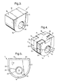
- This recess may have a generally U-shaped base, and is shaped so as to receive a known cable seal insert 7 as shown in Figure 2.
- the cable seal insert 7 is positioned so that its U-shaped lower part 7a fits in the U-shaped base of the recess and so that its flat upper peripheral surface 7b contacts gasket 3.
- the cover 2 is shaped so as to provide cable guide means 9 which co-operate with the cable guide means of the base to form a closed passage.
- the cover also has recesses shaped so as to receive the projecting parts 10 of the cable inserts of Figure 2 when they are in place in the base.
- the gasket 3 may be so positioned that it is in contact with the inner side 7c of the flat peripheral surface of the cable seal insert when the cover is fixed to the base.
- the prior art cable seal insert 7 of Figure 3 is a one piece rubber moulding having opposed flat surfaces 11, 12 a curved peripheral surface 7a and an upper flat peripheral surface 7b.
- a central aperture 15 is provided for receiving a cable.
- a slit 16 in the insert may extend from the curved peripheral surface 11 to the central aperture 15 to allow the insert to be opened along the line of the split for the lateral insertion of a cable into the aperture.
- a cable seal insert 7 which is not according to the invention is shown in Figure 4.
- the two opposed plates 11, 12 are formed from non-elastomeric material 17, 18.
- a layer of gel sealing material 19 lies between the plates 11, 12.
- An aperture 15 of substantially uniform cross-section extends through each plate 11, 12 and through the layer of gel 19. Portions of the plates may be cut away at the top flat peripheral surfaces and the cutaway portions filled with gel 20, 21.
- a slit 16 connects the central aperture 15 to the outside curved peripheral surface 11.
- Each plate has a hinge 27 (e.g. a so-called "living hinge", i.e. integral with the plate) and another slit 25, to enable the slit 16 to be opened out.
- the gel sealing material can be seen to extend to the external peripheral surfaces of the insert around its entire periphery (although some of the periphery is hidden from view). As a result, the gel can form a continuous uninterrupted seal around the whole of the insert. Also, the gel can be seen to extend inwardly to the cavity 15, and as a result form a seal completely around a cable within the insert. This allows a gel seal to be formed between the cable and the closure into which the insert is positioned.
- the cable seal insert 7 As the cable seal insert 7 is pushed into a recess in the outlet of the closure, it may be axially compressed (as shown in Figure 5) due to the two plates being forced together, depending on the relative dimensions of the recess and the insert. This deforms the gel sealing material radially inwards and outwards, producing beads 22, 23 respectively, forcing it against the cable and the outlet of the closure.
- figure 5 shows the axially compressed seal insert without cable or closure. Because of the ability of the gel sealing material to be deformed or displaced in this way, the seal insert of the invention is able to accommodate and seal cables over a wide range of sizes and cross-sectional shape.
- FIGS 6A and 6B show two cable seal inserts 7 according to the invention. These two inserts are substantially identical to each other except that the one illustrated in Figure 6A has only one cable aperture 15 whereas the one illustrated in Figure 6B has four cable apertures 15. Instead of having hinges to enable a cable to be inserted into them by "side-entry" (as in Figure 4), these cable seal inserts each comprise two ( Figure 6A) or three ( Figure 6B) parts which are separable at 35, to permit such side-entry into the apertures. Also, the plates 11 and 12 of the cable seal inserts each have an opening 31 at each laterally extreme edge of their (upper) substantially planar peripheral surface 7b, into which opening some of the sealing material 33 (preferably gel) extends.
- the sealing material 33 preferably gel
- FIGs 7A, 7B and 7C show another cable insert 7 according to the invention, with the sealing material omitted for the sake of clarity.
- a gasket or other seal 37 e.g. an O-ring seal
- the other plate 11 has two barriers 39 for preventing the sealing material from escaping from between the plates 11 and 12 of the cable seal insert 7 in use.
- Each barrier 39 is situated at a comer of the plate 11 between the substantially planar surface 7b and the lateral part of the curved peripheral surface 7a.
- the barriers 39 each comprise an extension of the plate 11 towards the other plate 12.
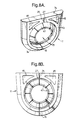
- Figures 8A and 8B illustrate one plate 11 of a cable seal insert 7 which does not have an opening at each laterally extreme edge of the plates according to the invention.
- the surface 43 of this plate which is in contact with the sealing material 19 in use, has two recesses 45 in it, into which the sealing material may expand and/or be displaced in use (as described above).
- the recesses have the advantage that expansion of the sealing material, e.g. due to a rise in temperature, or displacement of the sealing material, e.g. due to a large diameter cable being inserted into the cable seal insert, may be accommodated substantially without loss (or at least without significant loss) of sealing material from between the plates.
- Such recesses may be used in combination with barriers, e.g. as illustrated in Figure 7.
- the recesses 45 do not extend the whole way through the thickness of the plate, i.e. they are not open to the exterior of the cable seal insert.
- air (or other gas or vapour) in the recesses may be pressurized if some of the sealing material is displaced or expanded into the recesses, thereby applying an opposing compression to the sealing material (the advantage of which was mentioned above).
- the or each recess may be open to the exterior of the cable seal insert, e.g. by means of one or more holes through the plate in the recess. This has the advantage of releasing any pressure build-up in the recess due to displacement or expansion of the sealant into the recess, thereby providing containment of such displacement or expansion.
- the plate 11 shown in Figures 8A and 8B also includes a plurality of flaps 47 extending into the cable aperture 15 from the internal periphery of the aperture.
- the flaps 47 which can flex with respect to the plate 11, are provided around substantially the entire internal periphery of the cable aperture 15, and extend towards the opposite plate (not shown) as well as towards the centre of the cable aperture.
- the flaps 47 help to retain the sealing material between the plates, they enable the cable aperture to accommodate a significant range of sizes and cross-sectional shapes (e.g. oval cross-sections) of cable, and they may help to put the sealing material under compression by being resilient.
- the flaps may be referred to as "crowns" since they give the cable aperture 15 a crown-like appearance.
- the cable seal insert plates 11, 12 illustrated in figures 7 and 8 have bevelled perpipheral surfaces 7a. This has the advantage that the peripheral surfaces 7a of the plates are of reduced thickness, thus providing a corresponding increase in the thickness of sealing material which contacts the interior of the cable entry recess in the closure (and thereby substantially ensuring that the seal between the insert and the cable entry recess is as good as possible).
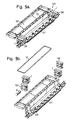
- Figure 9 shows a cable splice closure 125, comprising a casing which comprises a base 127 which has two casing end portions 129, and a cover 131.
- the closure 125 further comprises a sealing member 37 in the form of an O-ring seal and a pair of seal inserts 7.
- the closure also has strain-relief members 133 to grip the cables, and plugs 8 to block-off any unused cable ports 15 in the seal inserts.
- the O-ring sealing member 37 seals between the base 127 and the cover 131 and extends across the seal inserts 7 which are slotted into the casing end portions 129.
- the closure is fully disassembled, in Figure 9a it is partially assembled, and in Figure 9c it is fully assembled and closed around a splice between cables 137.
Landscapes
- Cable Accessories (AREA)
- Installation Of Indoor Wiring (AREA)
Claims (12)
- Pièce rapportée (7) pour le scellement étanche d'un câble, destinée à sceller de façon étanche une entrée de câble dans une fermeture (125) comportant :dans laquelle une surface périphérique (7b) de la pièce rapportée (7) pour le scellement étanche, qui est sensiblement parallèle au ou à chaque orifice (15) pour câble, est sensiblement plane, caractérisée en ce que, dans au moins l'une des plaques (11, 12), il y a une ouverture (31) à chaque bord latéralement extrême de sa surface périphérique sensiblement plane (7b), ouverture (31) dans laquelle, au moins lors de l'utilisation, une partie de la matière (33) de scellement étanche s'étend.(a) au moins deux plaques (11, 12) à travers chacune d'elles s'étend, au moins lors de l'utilisation, au moins un orifice (15) pour un câble ; et(b) une matière (33) de scellement étanche placée entre les plaques (11, 12) ;
- Pièce rapportée pour le scellement étanche d'un câble selon la revendication 1, dans laquelle la pièce rapportée, en plus de la surface périphérique sensiblement plane, est délimitée par une surface périphérique courbe unique (7a) sensiblement parallèle au ou à chaque orifice pour câble.
- Pièce rapportée pour le scellement étanche d'un câble selon la revendication 1 ou la revendication 2, dans laquelle une fente (16, 25, 35) s'étend depuis une surface périphérique (7a) de la pièce rapportée (7) pour le scellement étanche jusqu'au ou à chaque orifice pour câble, afin de permettre à la pièce rapportée de scellement étanche d'être ouverte pour une introduction latérale d'un câble.
- Pièce rapportée pour le scellement étanche d'un câble selon l'une quelconque des revendications précédentes, dans laquelle une surface (43) d'au moins l'une des plaques (11), laquelle surface est en contact avec la matière (33) de scellement étanche, présente en elle au moins un évidement (45) dans lequel une partie de la matière de scellement étanche peut s'expanser et/ou être déplacée lors de l'utilisation.
- Pièce rapportée pour le scellement étanche d'un câble selon l'une quelconque des revendications précédentes, qui comprend une ou plusieurs barrières (39) destinées à empêcher sensiblement la matière de scellement étanche (33) de s'écarter depuis une partie de la périphérie de la pièce rapportée (7) pour le scellement étanche.
- Pièce rapportée pour le scellement étanche d'un câble selon la revendication 5, dans laquelle la ou chaque barrière est située à un angle de ladite plaque (11) entre la surface sensiblement plane (7b) et une surface périphérique latérale (7a) de celle-ci.
- Pièce rapportée pour le scellement étanche d'un câble selon l'une quelconque des revendications précédentes, dans laquelle chaque plaque (11, 12) comporte plusieurs pattes (47) s'étendant dans le ou chaque orifice (15) pour câble depuis la périphérie intérieure de l'orifice.
- Pièce rapportée pour le scellement étanche d'un câble selon l'une quelconque des revendications précédentes, dans laquelle la matière de scellement étanche (33) est un gel.
- Pièce rapportée pour le scellement étanche d'un câble selon l'une quelconque des revendications précédentes, dans laquelle la matière de scellement étanche (33) présente un ou plusieurs de : une pénétration de cône de 100-350 (10-1 mm) ; et un allongement à la rupture d'au moins 200 % ; et une dureté Stevens-Volland de 60 à 130 g.
- Pièce rapportée pour le scellement étanche d'un câble selon l'une quelconque des revendications précédentes, dans laquelle au moins l'une des plaques (11, 12), avantageusement chaque plaque, présente une dureté Shore A supérieure à 90.
- Fermeture (125) pour épissure de câble, comportant un boítier sensiblement rigide comprenant une base (127) et un couvercle (131) reliés de façon étanche l'un à l'autre, lors de l'utilisation, par un élément d'étanchéité à garniture (37), la base et/ou le couvercle présentant un ou plusieurs évidements (129) d'entrée de câble, et dans laquelle le ou chaque évidement est scellé de façon étanche, lors de l'utilisation, par une pièce rapportée (7) pour le scellement étanche d'un câble reçu dans cet évidement et s'appliquant en appui contre l'élément d'étanchéité à garniture entre la base et le couvercle, la pièce rapportée pour le scellement étanche d'un câble étant une pièce rapportée (7) pour le scellement étanche d'un câble selon l'une quelconque des revendications précédentes.
- Fermeture pour épissure de câble selon la revendication 11, dans laquelle l'élément (37) d'étanchéité à garniture s'étend sur la surface périphérique sensiblement plane (7b) d'une plaque (11, 12), présentant lesdites ouvertures (31) à chaque bord latéralement extrême de la surface (7b), dans lesquelles une partie de la matière de scellement étanche (33) s'étend.
Applications Claiming Priority (7)
| Application Number | Priority Date | Filing Date | Title |
|---|---|---|---|
| GBGB9513365.8A GB9513365D0 (en) | 1995-06-30 | 1995-06-30 | Cable splice closure |
| GB9513365 | 1995-06-30 | ||
| GBGB9523915.8A GB9523915D0 (en) | 1995-11-22 | 1995-11-22 | Cable seal insert |
| GB9523915 | 1995-11-22 | ||
| GBGB9603549.8A GB9603549D0 (en) | 1996-02-20 | 1996-02-20 | Cable seal insert |
| GB9603549 | 1996-02-20 | ||
| PCT/GB1996/001450 WO1997002637A1 (fr) | 1995-06-30 | 1996-06-18 | Insert d'etancheite de cable |
Publications (2)
| Publication Number | Publication Date |
|---|---|
| EP0835544A1 EP0835544A1 (fr) | 1998-04-15 |
| EP0835544B1 true EP0835544B1 (fr) | 2000-08-30 |
Family
ID=27267793
Family Applications (1)
| Application Number | Title | Priority Date | Filing Date |
|---|---|---|---|
| EP96918746A Expired - Lifetime EP0835544B1 (fr) | 1995-06-30 | 1996-06-18 | Insert d'etancheite de cable |
Country Status (10)
| Country | Link |
|---|---|
| US (1) | US6118076A (fr) |
| EP (1) | EP0835544B1 (fr) |
| JP (1) | JPH11508758A (fr) |
| AU (1) | AU6130396A (fr) |
| BR (1) | BR9609472A (fr) |
| CA (1) | CA2225819A1 (fr) |
| DE (1) | DE69610103T2 (fr) |
| ES (1) | ES2151171T3 (fr) |
| MX (1) | MX9800228A (fr) |
| WO (1) | WO1997002637A1 (fr) |
Families Citing this family (37)
| Publication number | Priority date | Publication date | Assignee | Title |
|---|---|---|---|---|
| JPH11508758A (ja) * | 1995-06-30 | 1999-07-27 | エヌ・ヴェ・レイケム・ソシエテ・アノニム | ケーブルシールインサート |
| US6563049B2 (en) * | 1998-02-24 | 2003-05-13 | Lindy Lawrence May | Modular electrical system |
| SE515160C2 (sv) * | 1999-10-08 | 2001-06-18 | Roxtec Ab | Kabelgenomföring |
| JP4493867B2 (ja) * | 2001-02-26 | 2010-06-30 | トキコテクノ株式会社 | 給油装置 |
| US6650033B2 (en) | 2001-08-06 | 2003-11-18 | Tyco Electronics Corporation | Foamable coupling for lamp assembly and methods for using the coupling |
| SE520363C2 (sv) * | 2001-12-14 | 2003-07-01 | Roxtec Int Ab | Genomföringsanordning för genomföring av långsträckt ledning genom en öppning i en vägg |
| US6888067B1 (en) * | 2002-10-30 | 2005-05-03 | Delaware Capital Formation, Inc. | Cable sealing apparatus and method |
| US6816372B2 (en) * | 2003-01-08 | 2004-11-09 | International Business Machines Corporation | System, method and apparatus for noise and heat suppression, and for managing cables in a computer system |
| US6953897B2 (en) * | 2003-08-21 | 2005-10-11 | International Business Machines Corporation | Device and method for clamping and grounding a cable |
| DE102004005094A1 (de) * | 2004-01-27 | 2005-08-18 | Carl Zeiss | Gerätehaltevorrichtung |
| US7355130B2 (en) * | 2004-04-09 | 2008-04-08 | Siemens Information And Communication Networks, Inc. | Cable sealing device |
| US7388152B2 (en) * | 2005-08-29 | 2008-06-17 | Ocean Design, Inc. | Cable seal assembly and method |
| DE102005056215B4 (de) * | 2005-11-25 | 2013-05-23 | Rittal Gmbh & Co. Kg | Vorrichtung zum Führen von Kabeln oder Leitungen |
| DE102005056214B3 (de) * | 2005-11-25 | 2007-06-21 | Rittal Gmbh & Co. Kg | Vorrichtung zum Führen von Kabeln oder Leitungen |
| WO2009005416A1 (fr) * | 2007-07-05 | 2009-01-08 | Cyrba Ab | Accessoire de câble |
| US20100320694A1 (en) * | 2009-06-18 | 2010-12-23 | Musco Corporation | Apparatus, method, and system for sealing an object or a plurality of objects in an assembly and sealing said assembly around an aperture |
| WO2013105998A2 (fr) | 2011-02-16 | 2013-07-18 | Tyco Electronics Corporation | Fermeture pour fibres optiques |
| WO2012158233A1 (fr) * | 2011-03-07 | 2012-11-22 | Tyco Electronics Corporation | Enceinte d'épissure de fibres optiques comportant des ensembles plaques d'extrémité interchangeables et procédés les comprenant |
| DE102011103351B3 (de) * | 2011-05-27 | 2012-09-13 | Phoenix Contact Gmbh & Co. Kg | Dichtungselement und Anschlussgehäuse mit einem Dichtungselement |
| EP2538508B1 (fr) * | 2011-06-20 | 2016-10-05 | Tyco Electronics Raychem BVBA | Dispositif d'étanchéité pour filaments traversants |
| EP2557443B1 (fr) * | 2011-08-12 | 2014-03-05 | CCS Technology, Inc. | Fermeture de câble |
| US9476251B2 (en) | 2011-08-19 | 2016-10-25 | Aerovironment, Inc. | Water-tight compartment with removable hatch and two-sided gel seal for multiple conduit access |
| JP6061148B2 (ja) * | 2013-11-28 | 2017-01-18 | 住友電装株式会社 | コネクタ |
| EP3350639A2 (fr) | 2015-09-14 | 2018-07-25 | CommScope Connectivity Belgium BVBA | Boîtier étanche réouvrable |
| EP3436860B1 (fr) * | 2016-04-01 | 2021-03-10 | CommScope Connectivity Belgium BVBA | Joint à plusieurs éléments, et enceinte |
| US11002929B2 (en) * | 2017-03-01 | 2021-05-11 | CommScope Connectivity Belgium BVBA | Cable sealing unit with cable sealing modules |
| US11251596B2 (en) * | 2017-03-09 | 2022-02-15 | CommScope Connectivity Belgium BVBA | Gel seal and system incorporating gel seal |
| DE102017208477A1 (de) * | 2017-05-19 | 2018-11-22 | Icotek Project Gmbh & Co. Kg | Kabeldurchführung |
| DE102018101790A1 (de) * | 2018-01-26 | 2019-08-01 | Harting Electric Gmbh & Co. Kg | Dichteinsatz |
| JP7166077B2 (ja) * | 2018-06-06 | 2022-11-07 | 矢崎総業株式会社 | 屈曲プロテクタ |
| EP3853646A4 (fr) | 2018-09-21 | 2022-06-08 | CommScope Technologies LLC | Dispositif d'étanchéité de câble à fibre optique |
| BR112022004688A2 (pt) * | 2019-09-24 | 2022-06-14 | Commscope Technologies Llc | Vedação de cabo composto |
| CO2019015116A1 (es) * | 2019-12-31 | 2020-06-09 | Cardona Santiago Tovar | Sello que abraza los conductores eléctricos que atraviesan la cabeza de pozo y dispositivo que lo comprende |
| CN113531220A (zh) * | 2020-04-15 | 2021-10-22 | 康普技术有限责任公司 | 缆线密封装置和缆线密封系统 |
| JP7559374B2 (ja) * | 2020-06-19 | 2024-10-02 | 株式会社オートネットワーク技術研究所 | 配線モジュール及び弾性止水部材 |
| EP4695640A1 (fr) * | 2023-02-28 | 2026-02-18 | Hubbell Incorporated | Fermetures d'épissures de fibres optiques |
| US12640550B2 (en) * | 2023-06-13 | 2026-05-26 | Ampthink, Llc | Cable gland assembly |
Family Cites Families (15)
| Publication number | Priority date | Publication date | Assignee | Title |
|---|---|---|---|---|
| US4179319A (en) * | 1977-01-24 | 1979-12-18 | Raychem Corporation | Heat recoverable article and methods using same |
| US4287386A (en) * | 1979-07-27 | 1981-09-01 | Steven Scahill | End seal for conduits |
| BE885312A (fr) * | 1979-11-15 | 1981-01-16 | Morel Atel Electromec | Manchon pour proteger l'epissure de cables electriques ou telephoniques |
| US4332975A (en) * | 1980-06-13 | 1982-06-01 | Thomas & Betts Corporation | Sealed cable enclosure and cable assembly including same |
| US4492816A (en) * | 1982-06-30 | 1985-01-08 | Etablissements Morel, Ateliers Electromecaniques De Favieres | Splice-protecting sleeve for electric cables or telephone cables |
| NO159759C (no) * | 1985-08-12 | 1989-02-01 | Norsk Kabelfabrikk A S | Fremgangsm te til fremstilling av gass- og vanntettgjennomfoeringer og kabelgjennomfoering fremstilt ved fremgangsm ten. |
| DK158865C (da) * | 1986-05-13 | 1990-12-24 | Er Electric As | Fugtspaerrer |
| US5302779A (en) * | 1990-01-24 | 1994-04-12 | Etablissements Morel - Ateliers Electromechaniques De Favieres | Plug for fixing in an impermeable manner an electric cable to an opening and cable protection sleeve comprising such plugs |
| ES2039154B1 (es) * | 1991-04-22 | 1994-03-16 | Telefonica Nacional Espana Co | Caja para empalmes de fibra optica de acceso universal. |
| US5313546A (en) * | 1991-11-29 | 1994-05-17 | Sirti, S.P.A. | Hermetically sealed joint cover for fibre optic cables |
| GB9212625D0 (en) * | 1992-06-15 | 1992-07-29 | Raychem Sa Nv | Cable sealing device |
| MY112885A (en) * | 1993-12-01 | 2001-10-31 | N V Raychem S A | Sealing device. |
| US5529508A (en) * | 1994-04-01 | 1996-06-25 | Raychem Corporation | Sealing member |
| JPH11508758A (ja) * | 1995-06-30 | 1999-07-27 | エヌ・ヴェ・レイケム・ソシエテ・アノニム | ケーブルシールインサート |
| US5675124A (en) * | 1996-04-30 | 1997-10-07 | Stough; Robert Eugene | Grommet for a fiber optic enclosure |
-
1996
- 1996-06-18 JP JP9504900A patent/JPH11508758A/ja active Pending
- 1996-06-18 AU AU61303/96A patent/AU6130396A/en not_active Abandoned
- 1996-06-18 ES ES96918746T patent/ES2151171T3/es not_active Expired - Lifetime
- 1996-06-18 EP EP96918746A patent/EP0835544B1/fr not_active Expired - Lifetime
- 1996-06-18 CA CA002225819A patent/CA2225819A1/fr not_active Abandoned
- 1996-06-18 MX MX9800228A patent/MX9800228A/es not_active IP Right Cessation
- 1996-06-18 WO PCT/GB1996/001450 patent/WO1997002637A1/fr not_active Ceased
- 1996-06-18 DE DE69610103T patent/DE69610103T2/de not_active Expired - Fee Related
- 1996-06-18 BR BR9609472A patent/BR9609472A/pt not_active IP Right Cessation
- 1996-06-18 US US08/981,942 patent/US6118076A/en not_active Expired - Fee Related
Also Published As
| Publication number | Publication date |
|---|---|
| JPH11508758A (ja) | 1999-07-27 |
| CA2225819A1 (fr) | 1997-01-23 |
| BR9609472A (pt) | 1999-03-16 |
| AU6130396A (en) | 1997-02-05 |
| DE69610103T2 (de) | 2001-04-05 |
| EP0835544A1 (fr) | 1998-04-15 |
| DE69610103D1 (de) | 2000-10-05 |
| US6118076A (en) | 2000-09-12 |
| ES2151171T3 (es) | 2000-12-16 |
| MX9800228A (es) | 1998-07-31 |
| WO1997002637A1 (fr) | 1997-01-23 |
Similar Documents
| Publication | Publication Date | Title |
|---|---|---|
| US6118076A (en) | Cable seal insert | |
| CA2182804C (fr) | Etancheite | |
| US9340336B2 (en) | Extruded seal carrier and method of use | |
| AU721422B2 (en) | Cable closure | |
| US7477826B2 (en) | Cable enclosure assemblies and methods for using the same | |
| CA2347841C (fr) | Protection d'extremite de cable | |
| US6107571A (en) | Cable seal | |
| US20210254715A1 (en) | Multi-component seal and enclosure | |
| EP1794859A1 (fr) | Element d'etancheite pour enceintes | |
| CA2988835A1 (fr) | Enveloppes remplies de scellant et methode de protection environnementale d'une connexion | |
| EP0646294B1 (fr) | Dispositif pour l'obturation et/ou le passage de cables | |
| WO1996026566A1 (fr) | Element d'insertion pour l'obturation de cable |
Legal Events
| Date | Code | Title | Description |
|---|---|---|---|
| PUAI | Public reference made under article 153(3) epc to a published international application that has entered the european phase |
Free format text: ORIGINAL CODE: 0009012 |
|
| 17P | Request for examination filed |
Effective date: 19971209 |
|
| AK | Designated contracting states |
Kind code of ref document: A1 Designated state(s): DE ES FR GB |
|
| RIN1 | Information on inventor provided before grant (corrected) |
Inventor name: VAN HISSENHOVEN, MICHEL Inventor name: NOLF, JEAN-MARIE, ETIENNE Inventor name: BRUSSELMANS, JACQUES Inventor name: GRAULUS, HENDRIK Inventor name: DAMM, JESPER |
|
| GRAG | Despatch of communication of intention to grant |
Free format text: ORIGINAL CODE: EPIDOS AGRA |
|
| 17Q | First examination report despatched |
Effective date: 19990329 |
|
| GRAG | Despatch of communication of intention to grant |
Free format text: ORIGINAL CODE: EPIDOS AGRA |
|
| GRAH | Despatch of communication of intention to grant a patent |
Free format text: ORIGINAL CODE: EPIDOS IGRA |
|
| GRAH | Despatch of communication of intention to grant a patent |
Free format text: ORIGINAL CODE: EPIDOS IGRA |
|
| GRAA | (expected) grant |
Free format text: ORIGINAL CODE: 0009210 |
|
| AK | Designated contracting states |
Kind code of ref document: B1 Designated state(s): DE ES FR GB |
|
| REF | Corresponds to: |
Ref document number: 69610103 Country of ref document: DE Date of ref document: 20001005 |
|
| ET | Fr: translation filed | ||
| REG | Reference to a national code |
Ref country code: ES Ref legal event code: FG2A Ref document number: 2151171 Country of ref document: ES Kind code of ref document: T3 |
|
| PLBE | No opposition filed within time limit |
Free format text: ORIGINAL CODE: 0009261 |
|
| STAA | Information on the status of an ep patent application or granted ep patent |
Free format text: STATUS: NO OPPOSITION FILED WITHIN TIME LIMIT |
|
| 26N | No opposition filed | ||
| REG | Reference to a national code |
Ref country code: GB Ref legal event code: IF02 |
|
| PGFP | Annual fee paid to national office [announced via postgrant information from national office to epo] |
Ref country code: GB Payment date: 20030501 Year of fee payment: 8 |
|
| PGFP | Annual fee paid to national office [announced via postgrant information from national office to epo] |
Ref country code: FR Payment date: 20030602 Year of fee payment: 8 |
|
| PGFP | Annual fee paid to national office [announced via postgrant information from national office to epo] |
Ref country code: ES Payment date: 20030619 Year of fee payment: 8 |
|
| PGFP | Annual fee paid to national office [announced via postgrant information from national office to epo] |
Ref country code: DE Payment date: 20030630 Year of fee payment: 8 |
|
| PG25 | Lapsed in a contracting state [announced via postgrant information from national office to epo] |
Ref country code: GB Free format text: LAPSE BECAUSE OF NON-PAYMENT OF DUE FEES Effective date: 20040618 |
|
| PG25 | Lapsed in a contracting state [announced via postgrant information from national office to epo] |
Ref country code: ES Free format text: LAPSE BECAUSE OF NON-PAYMENT OF DUE FEES Effective date: 20040619 |
|
| PG25 | Lapsed in a contracting state [announced via postgrant information from national office to epo] |
Ref country code: DE Free format text: LAPSE BECAUSE OF NON-PAYMENT OF DUE FEES Effective date: 20050101 |
|
| GBPC | Gb: european patent ceased through non-payment of renewal fee |
Effective date: 20040618 |
|
| PG25 | Lapsed in a contracting state [announced via postgrant information from national office to epo] |
Ref country code: FR Free format text: LAPSE BECAUSE OF NON-PAYMENT OF DUE FEES Effective date: 20050228 |
|
| REG | Reference to a national code |
Ref country code: FR Ref legal event code: ST |
|
| REG | Reference to a national code |
Ref country code: ES Ref legal event code: FD2A Effective date: 20040619 |