EP0835732B1 - Spritzgiessdüse mit Führungs- und Dichtungsring - Google Patents
Spritzgiessdüse mit Führungs- und Dichtungsring Download PDFInfo
- Publication number
- EP0835732B1 EP0835732B1 EP97114939A EP97114939A EP0835732B1 EP 0835732 B1 EP0835732 B1 EP 0835732B1 EP 97114939 A EP97114939 A EP 97114939A EP 97114939 A EP97114939 A EP 97114939A EP 0835732 B1 EP0835732 B1 EP 0835732B1
- Authority
- EP
- European Patent Office
- Prior art keywords
- nozzle
- guide
- sealing ring
- injection molding
- mold
- Prior art date
- Legal status (The legal status is an assumption and is not a legal conclusion. Google has not performed a legal analysis and makes no representation as to the accuracy of the status listed.)
- Expired - Lifetime
Links
Images


Classifications
-
- B—PERFORMING OPERATIONS; TRANSPORTING
- B29—WORKING OF PLASTICS; WORKING OF SUBSTANCES IN A PLASTIC STATE IN GENERAL
- B29C—SHAPING OR JOINING OF PLASTICS; SHAPING OF MATERIAL IN A PLASTIC STATE, NOT OTHERWISE PROVIDED FOR; AFTER-TREATMENT OF THE SHAPED PRODUCTS, e.g. REPAIRING
- B29C45/00—Injection moulding, i.e. forcing the required volume of moulding material through a nozzle into a closed mould; Apparatus therefor
- B29C45/17—Component parts, details or accessories; Auxiliary operations
- B29C45/26—Moulds
- B29C45/27—Sprue channels ; Runner channels or runner nozzles
- B29C45/2701—Details not specific to hot or cold runner channels
- B29C45/2708—Gates
- B29C45/2711—Gate inserts
-
- B—PERFORMING OPERATIONS; TRANSPORTING
- B29—WORKING OF PLASTICS; WORKING OF SUBSTANCES IN A PLASTIC STATE IN GENERAL
- B29C—SHAPING OR JOINING OF PLASTICS; SHAPING OF MATERIAL IN A PLASTIC STATE, NOT OTHERWISE PROVIDED FOR; AFTER-TREATMENT OF THE SHAPED PRODUCTS, e.g. REPAIRING
- B29C45/00—Injection moulding, i.e. forcing the required volume of moulding material through a nozzle into a closed mould; Apparatus therefor
- B29C45/17—Component parts, details or accessories; Auxiliary operations
- B29C45/26—Moulds
- B29C45/27—Sprue channels ; Runner channels or runner nozzles
-
- B—PERFORMING OPERATIONS; TRANSPORTING
- B29—WORKING OF PLASTICS; WORKING OF SUBSTANCES IN A PLASTIC STATE IN GENERAL
- B29C—SHAPING OR JOINING OF PLASTICS; SHAPING OF MATERIAL IN A PLASTIC STATE, NOT OTHERWISE PROVIDED FOR; AFTER-TREATMENT OF THE SHAPED PRODUCTS, e.g. REPAIRING
- B29C45/00—Injection moulding, i.e. forcing the required volume of moulding material through a nozzle into a closed mould; Apparatus therefor
- B29C45/17—Component parts, details or accessories; Auxiliary operations
- B29C45/26—Moulds
- B29C45/27—Sprue channels ; Runner channels or runner nozzles
- B29C45/2737—Heating or cooling means therefor
- B29C2045/274—Thermocouples or heat sensors
-
- B—PERFORMING OPERATIONS; TRANSPORTING
- B29—WORKING OF PLASTICS; WORKING OF SUBSTANCES IN A PLASTIC STATE IN GENERAL
- B29C—SHAPING OR JOINING OF PLASTICS; SHAPING OF MATERIAL IN A PLASTIC STATE, NOT OTHERWISE PROVIDED FOR; AFTER-TREATMENT OF THE SHAPED PRODUCTS, e.g. REPAIRING
- B29C45/00—Injection moulding, i.e. forcing the required volume of moulding material through a nozzle into a closed mould; Apparatus therefor
- B29C45/17—Component parts, details or accessories; Auxiliary operations
- B29C45/26—Moulds
- B29C45/27—Sprue channels ; Runner channels or runner nozzles
- B29C2045/2759—Nozzle centering or guiding means
-
- B—PERFORMING OPERATIONS; TRANSPORTING
- B29—WORKING OF PLASTICS; WORKING OF SUBSTANCES IN A PLASTIC STATE IN GENERAL
- B29C—SHAPING OR JOINING OF PLASTICS; SHAPING OF MATERIAL IN A PLASTIC STATE, NOT OTHERWISE PROVIDED FOR; AFTER-TREATMENT OF THE SHAPED PRODUCTS, e.g. REPAIRING
- B29C45/00—Injection moulding, i.e. forcing the required volume of moulding material through a nozzle into a closed mould; Apparatus therefor
- B29C45/17—Component parts, details or accessories; Auxiliary operations
- B29C45/26—Moulds
- B29C45/27—Sprue channels ; Runner channels or runner nozzles
- B29C2045/2761—Seals between nozzle and mould or gate
Definitions
- This invention relates generally to injection molding and more particularly to a guide and sealing ring to be mounted on a heated nozzle according to the preamble of claim 1.
- EP-A-0 475 143 discloses an injection molding apparatus as indicated above.
- injection molding apparatus having a number of heated nozzles extending from a melt distribution manifold is well known.
- the nozzles are inserted into wells in the mold and if the nozzles are not all aligned exactly one or more of them can be damaged.
- U.S. Patent Number 4,768,945 to Schmidt et al. which issued September 6, 1988, providing a sealing and locating flange which bridges the insulative air space between each heated nozzle and the surrounding cooled mold is also known.
- the applicant's U.S. Patent Number 5,346,388 which issued September 13, 1994 shows the operating temperatures being monitored by a thermocouple element bent to extend rearwardly into a hole in the front end of each nozzle.
- Patent Number 5,326,251 which issued July 5, 1994 discloses wrapping a wire around each nozzle to hold the thermocouple element in place against the nozzle. While these previous arrangements are very satisfactory for many applications, the previous sealing and locating ring requires the nozzle to be made with a seat to receive it and has no provision for a thermocouple element extending through it.
- an injection molding apparatus having at least one heated nozzle extending forwardly into a well with a generally cylindrical wall in a cooled mold with an insulative air space extending between the at least one heated nozzle and the surrounding cooled mold the at least one nozzle having a rear end, a front end, at least a portion adjacent the front end with a generally cylindrical outer surface, and a melt bore extending therethrough from the rear end to the front end in alignment with a gate leading to a cavity in the mold, the apparatus further comprising; a guide and sealing ring adapted to be mounted around the outer cylindrical surface adjacent the front end of the at least one nozzle prior to insertion of the at least one nozzle into the well in the mold, the guide and sealing ring having an inner surface and an outer surface, the inner surface forming a cylindrical opening which fits around the outer cylindrical surface of the at least one nozzle, the outer surface of the guide and sealing ring fitting in the well to guide the front end of the at least one nozzle during insertion of the at least
- FIG. 1 shows a melt distribution manifold 10 with four elongated heated nozzles 12 extending from it in position for mounting in a mold 14.
- each nozzle 12 has a threaded rear end (not shown) screwed into the melt distribution manifold 10, and a cylindrical outer surface 16 extending to a front end 18, although many other configurations can be used.
- the melt distribution manifold 10 is heated by electrical plate heaters 20 attached to it, and has a melt passage (not shown) branching from a central inlet 22 to extend into alignment with a central bore 24 in each nozzle 12.
- each nozzle 12 is heated by an integral electrical heating element 26 which extends in a spiral around the central bore 24.
- the mold 14 is cooled by pumping cooling water through cooling conduits 28.
- Each nozzle 12 is received in a well 30 in the mold 14 with an insulative air space 32 extending between the heated nozzle 12 and the cylindrical wall 34 of the surrounding cooled mold 14.
- a removable two-piece nozzle seal 36 is mounted in the front end 18 of each nozzle 12.
- the two-piece seal 36 has a hollow inner piece 38 which is retained in place in a seat 40 in the front end 18 of the nozzle 12 by a coaxial outer piece 42 which is screwed tightly in place.
- the two-piece seal 36 extends across the insulative air space 32 and is received in a cylindrical opening 44 in the mold 14 with a front face 46 which is flush with the cavity 48 at the processing temperature.
- the inner piece 38 has a bore 50 which is in alignment with the central bore 24 of the nozzle to convey the melt to the gate 52 in the outer piece 42 leading to the cavity 48.
- thermocouple element 54 which extends through the air space 32 between the nozzle 12 and the mold 14 and is bent to be received in a rearwardly extending hole 56 in the front end 18 of the nozzle 12.
- the thermocouple element 54 is held against the cylindrical surface 16 of the nozzle by a high temperature wire 58 wrapped around the nozzle 12 as described below.
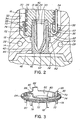
- a guide and sealing ring 60 is mounted around the front end 18 of each nozzle 12.
- the guide and sealing ring 60 is made of stainless steel with an inner surface 62 and an outer surface 64.
- the inner surface 62 forms a cylindrical opening 66 which fits around the outer cylindrical surface 16 of the nozzle 12.
- the ring 60 has a radial gap 68 to allow for greater tolerance in the size of the outer surface 16 of the nozzle 12 and the inner surface 62 of ring 60 while still ensuring a tight fit.
- the width of the gap 68 has been exaggerated in the drawings for the purpose of illustration. In fact, the gap 68 is quite narrow so it can be closed by a ceramic sealant, as described below.
- the ring can be made continuous to fit over the nozzle.
- the outer surface 64 forms an outwardly extending flange portion 70 with a number of inwardly sloping guide ribs 72 extending forwardly therefrom.
- the size of the flange portion 70 is made to just fit inside the cylindrical well 30 to provide a secondary seal in case there is any leakage of pressurized melt into the space 76 between the two-piece seal 36 and the guide and sealing ring 60.
- the outer surface 64 can form a continuous slope forwardly from the flange portion 70, but having the spaced guide ribs 72 somewhat reduces heat loss from the heated nozzle 12 to the cooled mold 14.
- the guide and sealing ring 60 has a number of forwardly extending fingers 78 spaced around it.
- the inner surface 62 of the ring 60 has a groove 80 in it and the finger 82 adjacent the groove 80 is positioned further outward and is longer than the others.
- the guide and sealing ring 60 is mounted over the front end 18 of the nozzle 12 with the thermocouple element 54 extending through the groove 80 and the fingers 78 are then bent with a suitable tool such as a hammer 84 over the front end 18 of the nozzle 12 to secure the ring 60 in place.
- finger 82 is bent over the thermocouple element 54 to hold it in place in the hole 56.
- thermosetting ceramic sealant such as CERAMABOND 668 (trade name of Aremco) is applied from a pneumatic dispensing tube 86 or syringe into the spaces between the ring 60 and the nozzle 12 including the thin gap 68 and the groove 80 for the thermocouple element 54.
- the nozzles 12 are then heated in an oven to a temperature of approximately 200°C to solidify the thermosetting ceramic sealant.
- the guide and sealing ring 60 also has a number of rearwardly extending fingers 88 spaced around it.
- the rearwardly extending fingers 88 each have an outwardly facing notch 90 to receive the wire 58 wound around the nozzle to secure the thermocouple element 54 and the ring 60 itself in place against the outer surface 16 of the nozzle 12.
- the injection molding system is assembled by lowering the melt distribution manifold 10 with the nozzles 12 attached into place in the mold 14 as shown in Figure 1.
- the sloped guide ribs 72 initially guide the nozzles 12 into the wells 30 and then the flange portion 70 aligns each nozzle 12 so that the two-piece seal 36 enters the cylindrical opening 44 without any damage to its front face 46.
- the cylindrical opening 44 has a beveled edge 92 to ensure there is only smooth contact between them.
- melt is applied from a molding machine (not shown) to the central inlet 22 of the melt passage according to a predetermined cycle.
- the melt flows through the melt distribution manifold 10, nozzles 12, nozzle seals 36 and gates 52 into the cavities 48. After the cavities 48 are filled and a suitable packing and cooling period has expired, the injection pressure is released and the melt conveying system is decompressed to avoid stringing through the open gates 52.
- the mold 14 is then opened to eject the molded products. After ejection, the mold 14 is closed and the cycle is repeated continuously with a cycle time dependent upon the size of the cavities 48 and the type of material being molded.
Landscapes
- Engineering & Computer Science (AREA)
- Manufacturing & Machinery (AREA)
- Mechanical Engineering (AREA)
- Injection Moulding Of Plastics Or The Like (AREA)
- Moulds For Moulding Plastics Or The Like (AREA)
Claims (7)
- Spritzgießvorrichtung mit zumindest einer beheizten Düse (12), die sich nach vorwärts in eine Bohrung (30) mit einer im wesentlichen zylindrischen Wand (34) in einer gekühlten Form (14) erstreckt, mit einem isolierenden Luftraum (32), der sich zwischen der zumindest einen beheizten Düse (12) und der umgebenden, gekühlten Form (14) erstreckt, wobei die zumindest eine Düse (12) ein hinteres Ende, ein vorderes Ende (18), zumindest einen Abschnitt benachbart zu dem vorderen Ende (18) mit einer im wesentlichen zylindrischen Außenoberfläche (16) und eine Schmelzbohrung (24) aufweist, die sich durch diese hindurch von dem hinteren Ende zu dem vorderen Ende (18) in Ausrichtung mit einem Anschnitt (52) erstreckt, der sich zu einem Formhohlraum (48) in der Form (14) erstreckt, wobei die Vorrichtung außerdem aufweist:einen Führungs- und Dichtungsring (60), vorgesehen rund um die zylindrische Außenoberfläche (16) benachbart dem vorderen Ende (18) der zumindest einen Düse (12) vor dem Einsetzen der zumindest einen Düse (12) in die Bohrung (30) in die Form (14) montiert zu werden, wobei der Führungs- und Dichtungsring (60) eine Innenoberfläche (62) und eine Außenoberfläche (64) aufweist, die Innenoberfläche (62) eine zylindrische Öffnung (66) bildet, die um die zylindrische Außenoberfläche (16) der zumindest einen Düse (12) paßt, wobei die Außenoberfläche (64) des Führungs- und Dichtungsrings (60) in die Bohrung (30) paßt, um das vordere Ende (18) der zumindest einen Düse (12) während des Einsetzens der zumindest einen Düse (12) in die Bohrung (30) in der Form (14) zu führen und eine Dichtung zwischen der Außenoberfläche (64) des Führungs- und Dichtungsrings (60) und der im wesentlichen zylindrischen Wandung (34) der Bohrung (30) zu schaffen, dadurch gekennzeichnet, das der Führungs- und Dichtungsring (60) eine Mehrzahl von sich nach vorwärts erstreckenden Fingern (78) aufweist, die in Umfangsrichtung beabstandet sind, um den Führungs- und Dichtungsring (60) an Ort und Stelle zu halten.
- Spritzgießvorrichtung nach Anspruch 1, dadurch gekennzeichnet, daß die Auβenoberfläche (64) des Führungs- und Dichtungsrings (60) abgeschrägt ist, um einen sich in Umfangsrichtung erstreckenden Flanschabschnitt (70) zu bilden, der in die Bohrung (30) in eine Form (14) paßt.
- Spritzgießvorrichtung nach Anspruch 2, dadurch gekennzeichnet, daß eine Mehrzahl von einwärts geneigten, beabstandeten Führungsrippen (72) sich nach vorwärts von dem Flanschabschnitt (70) aus erstrecken.
- Spritzgießvorrichtung nach Anspruch 2, wobei die sich nach vorwärts erstreckenden Finger (78) vorgesehen sind, radial einwärts über das Vorderende (18) der Düse (14) gebogen zu werden, nachdem der Führungs- und Dichtungsring (60) rund um die zylindrische Außenoberfläche (16) der Düse (12) montiert ist.
- Spritzgießvorrichtung nach zumindest einem der Ansprüche 1 bis 4, wobei das Vorderende (18) der Düse (12) eine Bohrung (56) aufweist, um in dieser ein Thermoelement (54) aufzunehmen und die Innenoberfläche (62) des Führungs- und Dichtungsringes (60) eine Nut (80) aufweist, um darin durch diese hindurch das Thermoelement (65) aufzunehmen.
- Spritzgießvorrichtung nach zumindest einem der Ansprüche 1 bis 5, wobei einer der sich nach vorwärts erstreckenden Finger (78) vorgesehen ist, über das Thermoelement (54) auf das Vorderende (18) der Düse (12) gebogen zu werden und das Thermoelement an Ort und Stelle in der Öffnung in dem vorderen Ende der Düse zu halten.
- Spritzgießvorrichtung nach zumindest einem der Ansprüche 1 bis 6, wobei ein Führungs- und Dichtungsring (60) eine Mehrzahl von sich nach rückwärts erstrekkenden Finger (88) aufweist, die in Umfangsrichtung beabstandet sind, wobei jeder der sich nach rückwärts erstreckenden Finger (88) eine nach außen weisende Ausnehmung (90) aufweist, vorgesehen zum Aufnehmen eines Drahtes (98), der um die Düse (12) gewickelt wird und zum Befestigen des Thermoelementes an Ort und Stelle gegen die Außenoberfläche der Düse.
Applications Claiming Priority (2)
| Application Number | Priority Date | Filing Date | Title |
|---|---|---|---|
| CA002187497A CA2187497C (en) | 1996-10-09 | 1996-10-09 | Injection molding nozzle guide and sealing ring |
| CA187497 | 1996-10-09 |
Publications (2)
| Publication Number | Publication Date |
|---|---|
| EP0835732A1 EP0835732A1 (de) | 1998-04-15 |
| EP0835732B1 true EP0835732B1 (de) | 2002-03-13 |
Family
ID=4159050
Family Applications (1)
| Application Number | Title | Priority Date | Filing Date |
|---|---|---|---|
| EP97114939A Expired - Lifetime EP0835732B1 (de) | 1996-10-09 | 1997-08-28 | Spritzgiessdüse mit Führungs- und Dichtungsring |
Country Status (7)
| Country | Link |
|---|---|
| US (1) | US5795599A (de) |
| EP (1) | EP0835732B1 (de) |
| JP (1) | JP4118983B2 (de) |
| CA (1) | CA2187497C (de) |
| DE (1) | DE69710982T2 (de) |
| ES (1) | ES2171794T3 (de) |
| PT (1) | PT835732E (de) |
Families Citing this family (23)
| Publication number | Priority date | Publication date | Assignee | Title |
|---|---|---|---|---|
| CA2250598A1 (en) * | 1998-10-16 | 2000-04-16 | Jobst Ulrich Gellert | Apparatus for locating and sealing an injection molding nozzle |
| CA2250599A1 (en) * | 1998-10-16 | 2000-04-16 | Jobst Ulrich Gellert | Apparatus and method of making an injection molding nozzle with tip insert |
| US6318990B1 (en) | 1998-10-16 | 2001-11-20 | Mold-Masters Limited | Injection molding nozzle apparatus |
| DE10080726B4 (de) * | 1999-02-10 | 2007-03-01 | Ju-Oh Inc., Hiratsuka | Form für eine Heißanguß-Spritzmaschine sowie Verfahren zum Herstellen derselben |
| CA2262175C (en) | 1999-02-16 | 2008-02-12 | Mold-Masters Limited | Injection molding apparatus with removable nozzle seal |
| US6328554B1 (en) * | 1999-07-07 | 2001-12-11 | Husky Injection Molding System, Ltd. | Valve gating arrangement for an insulated runner |
| US6769901B2 (en) * | 2000-04-12 | 2004-08-03 | Mold-Masters Limited | Injection nozzle system for an injection molding machine |
| ITPN20010003U1 (it) * | 2001-01-25 | 2002-07-25 | Sipa Spa | Dispositivo per il rilevamento di variazioni di temperatura con alloggiamento per il sensore |
| CA2358187A1 (en) * | 2001-10-03 | 2003-04-03 | Mold-Masters Limited | Nozzle seal |
| CA2358148A1 (en) | 2001-10-03 | 2003-04-03 | Mold-Masters Limited | A nozzle |
| US6962492B2 (en) * | 2001-10-05 | 2005-11-08 | Mold-Masters Limited | Gap seal between nozzle components |
| CA2463498C (en) | 2001-10-12 | 2012-04-24 | Mold-Masters Limited | Valve pin with thermocouple |
| US7182893B2 (en) | 2002-10-11 | 2007-02-27 | Mold-Masters Limited | Valve gated nozzle having a valve pin with a sensor |
| US7128566B2 (en) * | 2002-02-21 | 2006-10-31 | Mold-Masters Limited | Valve pin guiding tip for a nozzle |
| JP2005534534A (ja) * | 2002-07-30 | 2005-11-17 | モールド‐マスターズ、リミテッド | 射出成型装置用バルブピン案内・芯合わせシステム |
| US7137807B2 (en) * | 2002-11-21 | 2006-11-21 | Mold-Masters Limited | Hot runner nozzle with a tip, a tip surrounding piece and an alignment piece |
| CA2452112A1 (en) * | 2002-12-09 | 2004-06-09 | Mold-Masters Limited | Nozzle tip and seal |
| DE102004038056B3 (de) * | 2004-08-05 | 2006-03-09 | Otto Männer Innovation GmbH | Heißkanaldüse |
| US7370417B2 (en) * | 2005-12-09 | 2008-05-13 | Mold-Masters (2007) Limited | Method of installing a mold gate insert in an injection molding apparatus |
| US7361010B2 (en) * | 2006-01-26 | 2008-04-22 | D-M-E Company | Apparatus for injection molding |
| DE102008017931A1 (de) * | 2008-04-08 | 2009-10-15 | Psg Plastic Service Gmbh | Heißkanaldüse mit anlagefreier Vorzentrierung |
| CA2832077C (en) * | 2011-04-26 | 2016-09-13 | Husky Injection Molding Systems Ltd. | Mold-tool system including nozzle-tip assembly configured for reduced axial tilting |
| DE102016203995A1 (de) * | 2016-03-10 | 2017-09-14 | Otto Männer Innovation GmbH | Heißkanalsystem und damit verbundene Düsenheizeinrichtungen |
Family Cites Families (6)
| Publication number | Priority date | Publication date | Assignee | Title |
|---|---|---|---|---|
| CA1261573A (en) * | 1987-10-16 | 1989-09-26 | Harald H. Schmidt | Injection molding nozzle having grounded heating element brazed into pointed tip |
| ES2069567T3 (es) * | 1988-12-05 | 1995-05-16 | Mold Masters Ltd | Aparato de moldeo por inyeccion dotado de insertos enfriados por liquido. |
| DE4028660A1 (de) * | 1990-09-10 | 1992-03-26 | Incoe International Inc Zweign | Heisskanal-verteilersystem |
| US5324191A (en) * | 1992-09-30 | 1994-06-28 | Husky Injection Molding Systems Ltd. | Sealed edge gate |
| CA2101480C (en) * | 1993-07-28 | 2001-09-11 | Jobst Ulrich Gellert | Injection molding nozzle which retains a thermocouple element |
| US5326251A (en) * | 1993-12-06 | 1994-07-05 | Gellert Jobst U | Heated injection molding nozzle with alternate thermocouple bores |
-
1996
- 1996-10-09 CA CA002187497A patent/CA2187497C/en not_active Expired - Fee Related
- 1996-11-12 US US08/747,438 patent/US5795599A/en not_active Expired - Lifetime
-
1997
- 1997-08-28 EP EP97114939A patent/EP0835732B1/de not_active Expired - Lifetime
- 1997-08-28 PT PT97114939T patent/PT835732E/pt unknown
- 1997-08-28 DE DE69710982T patent/DE69710982T2/de not_active Expired - Lifetime
- 1997-08-28 ES ES97114939T patent/ES2171794T3/es not_active Expired - Lifetime
- 1997-09-30 JP JP26649697A patent/JP4118983B2/ja not_active Expired - Fee Related
Also Published As
| Publication number | Publication date |
|---|---|
| DE69710982D1 (de) | 2002-04-18 |
| DE69710982T2 (de) | 2002-07-04 |
| US5795599A (en) | 1998-08-18 |
| JPH11936A (ja) | 1999-01-06 |
| ES2171794T3 (es) | 2002-09-16 |
| JP4118983B2 (ja) | 2008-07-16 |
| CA2187497C (en) | 2005-06-28 |
| CA2187497A1 (en) | 1998-04-09 |
| EP0835732A1 (de) | 1998-04-15 |
| PT835732E (pt) | 2002-08-30 |
Similar Documents
| Publication | Publication Date | Title |
|---|---|---|
| EP0835732B1 (de) | Spritzgiessdüse mit Führungs- und Dichtungsring | |
| US5494433A (en) | Injection molding hot tip side gate seal having a circumferential rim | |
| CA2152664C (en) | Injection molding nozzle with pressed in heating element and integral collar portion | |
| US5591465A (en) | Side gated injection molding apparatus with radially mounted gate inserts | |
| EP0820847B1 (de) | Spritzgiessdüseverfahren unter Verwendung eines Elementes zum Fixieren und Abdichten eines Kontakdrahtes | |
| US20020117777A1 (en) | Injection molding cooled cavity insert | |
| CA2127211C (en) | Injection molding nozzle with removable collar portion | |
| US6318990B1 (en) | Injection molding nozzle apparatus | |
| EP0842751B1 (de) | Spritzgiessdüse mit seitlichen Anschnitteinsätzen und Dichtungsring | |
| CA2030287C (en) | Injection molding apparatus having separate heating element in the cavity forming insert | |
| CA2047461A1 (en) | Injection molding manifold with removable inserts | |
| US5507636A (en) | Injection holding heated nozzle with protective tubes | |
| EP0743158A1 (de) | Heisse seitliche Spritzgiessanschnittabdichtung mit Umfangsrand | |
| EP0715940B1 (de) | Spritzgiessdüse mit trennbaren Kern und einteiligem Kragen | |
| EP0638406B1 (de) | Spritzgiessdüse mit einem Thermoelement | |
| US5474440A (en) | Injection molding nozzle with collar having locating and retaining lug protions | |
| US5536165A (en) | Injection molding apparatus with nozzle advanceable to mount side gate seals | |
| EP0633118B1 (de) | Zweiteilige Dichtung für Spritzgiessdüse | |
| US4795338A (en) | Mounting for injection molding nozzle | |
| EP0743157A1 (de) | Spritzgiessvorrichtung mit vorschiebbarer Düse zur Montage von seitlichen Anschnittabdichtungen | |
| EP0695618B1 (de) | Sprizgiessdüse mit Kragen der Positionierungs- und Haltenockenteile aufweist | |
| EP0609676B1 (de) | Spritzgiessdüse mit Thermoelementrohr | |
| CA2250598A1 (en) | Apparatus for locating and sealing an injection molding nozzle | |
| CA2102854C (en) | Heated injection molding nozzle with alternate thermocouple bores |
Legal Events
| Date | Code | Title | Description |
|---|---|---|---|
| PUAI | Public reference made under article 153(3) epc to a published international application that has entered the european phase |
Free format text: ORIGINAL CODE: 0009012 |
|
| AK | Designated contracting states |
Kind code of ref document: A1 Designated state(s): CH DE ES FR GB IT LI LU NL PT |
|
| AX | Request for extension of the european patent |
Free format text: AL;LT;LV;RO;SI |
|
| 17P | Request for examination filed |
Effective date: 19980916 |
|
| AKX | Designation fees paid |
Free format text: CH DE ES FR GB IT LI LU NL PT |
|
| RBV | Designated contracting states (corrected) |
Designated state(s): CH DE ES FR GB IT LI LU NL PT |
|
| 17Q | First examination report despatched |
Effective date: 19991223 |
|
| GRAG | Despatch of communication of intention to grant |
Free format text: ORIGINAL CODE: EPIDOS AGRA |
|
| GRAG | Despatch of communication of intention to grant |
Free format text: ORIGINAL CODE: EPIDOS AGRA |
|
| GRAH | Despatch of communication of intention to grant a patent |
Free format text: ORIGINAL CODE: EPIDOS IGRA |
|
| GRAH | Despatch of communication of intention to grant a patent |
Free format text: ORIGINAL CODE: EPIDOS IGRA |
|
| REG | Reference to a national code |
Ref country code: GB Ref legal event code: IF02 |
|
| GRAA | (expected) grant |
Free format text: ORIGINAL CODE: 0009210 |
|
| AK | Designated contracting states |
Kind code of ref document: B1 Designated state(s): CH DE ES FR GB IT LI LU NL PT |
|
| REG | Reference to a national code |
Ref country code: CH Ref legal event code: NV Representative=s name: PATENTANWALTSBUERO JEAN HUNZIKER Ref country code: CH Ref legal event code: EP |
|
| REF | Corresponds to: |
Ref document number: 69710982 Country of ref document: DE Date of ref document: 20020418 |
|
| ET | Fr: translation filed | ||
| REG | Reference to a national code |
Ref country code: PT Ref legal event code: SC4A Free format text: AVAILABILITY OF NATIONAL TRANSLATION Effective date: 20020514 |
|
| REG | Reference to a national code |
Ref country code: ES Ref legal event code: FG2A Ref document number: 2171794 Country of ref document: ES Kind code of ref document: T3 |
|
| PLBE | No opposition filed within time limit |
Free format text: ORIGINAL CODE: 0009261 |
|
| STAA | Information on the status of an ep patent application or granted ep patent |
Free format text: STATUS: NO OPPOSITION FILED WITHIN TIME LIMIT |
|
| 26N | No opposition filed |
Effective date: 20021216 |
|
| REG | Reference to a national code |
Ref country code: CH Ref legal event code: PUE Owner name: MOLD-MASTERS (2007) LIMITED Free format text: GELLERT, JOBST ULRICH#7A PRINCE STREET#GEORGETOWN ONTARIO L7G 2X1 (CA) -TRANSFER TO- MOLD-MASTERS (2007) LIMITED#233 ARMSTRONG AVENUE#GEORGETOWN ON L7G4X5 (CA) |
|
| REG | Reference to a national code |
Ref country code: GB Ref legal event code: 732E |
|
| REG | Reference to a national code |
Ref country code: PT Ref legal event code: PC4A Owner name: MOLD-MASTERS (2007) LIMITED, CA Effective date: 20080819 |
|
| NLS | Nl: assignments of ep-patents |
Owner name: MOLD-MASTERS (2007) LIMITED Effective date: 20080610 |
|
| PGFP | Annual fee paid to national office [announced via postgrant information from national office to epo] |
Ref country code: PT Payment date: 20080801 Year of fee payment: 12 Ref country code: NL Payment date: 20080728 Year of fee payment: 12 Ref country code: LU Payment date: 20080731 Year of fee payment: 12 Ref country code: ES Payment date: 20080818 Year of fee payment: 12 Ref country code: CH Payment date: 20080728 Year of fee payment: 12 |
|
| PGFP | Annual fee paid to national office [announced via postgrant information from national office to epo] |
Ref country code: IT Payment date: 20080812 Year of fee payment: 12 Ref country code: FR Payment date: 20080828 Year of fee payment: 12 |
|
| REG | Reference to a national code |
Ref country code: FR Ref legal event code: TP |
|
| PGFP | Annual fee paid to national office [announced via postgrant information from national office to epo] |
Ref country code: GB Payment date: 20080729 Year of fee payment: 12 |
|
| REG | Reference to a national code |
Ref country code: PT Ref legal event code: MM4A Free format text: LAPSE DUE TO NON-PAYMENT OF FEES Effective date: 20100301 |
|
| REG | Reference to a national code |
Ref country code: NL Ref legal event code: V1 Effective date: 20100301 Ref country code: CH Ref legal event code: PL |
|
| GBPC | Gb: european patent ceased through non-payment of renewal fee |
Effective date: 20090828 |
|
| PG25 | Lapsed in a contracting state [announced via postgrant information from national office to epo] |
Ref country code: PT Free format text: LAPSE BECAUSE OF NON-PAYMENT OF DUE FEES Effective date: 20100301 Ref country code: LI Free format text: LAPSE BECAUSE OF NON-PAYMENT OF DUE FEES Effective date: 20090831 Ref country code: CH Free format text: LAPSE BECAUSE OF NON-PAYMENT OF DUE FEES Effective date: 20090831 |
|
| REG | Reference to a national code |
Ref country code: FR Ref legal event code: ST Effective date: 20100430 |
|
| PG25 | Lapsed in a contracting state [announced via postgrant information from national office to epo] |
Ref country code: NL Free format text: LAPSE BECAUSE OF NON-PAYMENT OF DUE FEES Effective date: 20100301 Ref country code: FR Free format text: LAPSE BECAUSE OF NON-PAYMENT OF DUE FEES Effective date: 20090831 |
|
| REG | Reference to a national code |
Ref country code: ES Ref legal event code: FD2A Effective date: 20090829 |
|
| PG25 | Lapsed in a contracting state [announced via postgrant information from national office to epo] |
Ref country code: GB Free format text: LAPSE BECAUSE OF NON-PAYMENT OF DUE FEES Effective date: 20090828 |
|
| PG25 | Lapsed in a contracting state [announced via postgrant information from national office to epo] |
Ref country code: IT Free format text: LAPSE BECAUSE OF NON-PAYMENT OF DUE FEES Effective date: 20090828 |
|
| PG25 | Lapsed in a contracting state [announced via postgrant information from national office to epo] |
Ref country code: LU Free format text: LAPSE BECAUSE OF NON-PAYMENT OF DUE FEES Effective date: 20090828 |
|
| PG25 | Lapsed in a contracting state [announced via postgrant information from national office to epo] |
Ref country code: ES Free format text: LAPSE BECAUSE OF NON-PAYMENT OF DUE FEES Effective date: 20090829 |
|
| PGFP | Annual fee paid to national office [announced via postgrant information from national office to epo] |
Ref country code: DE Payment date: 20160721 Year of fee payment: 20 |
|
| REG | Reference to a national code |
Ref country code: DE Ref legal event code: R071 Ref document number: 69710982 Country of ref document: DE |