EP0835733B1 - Presse d'injection avec un dispositif de fermeture - Google Patents
Presse d'injection avec un dispositif de fermeture Download PDFInfo
- Publication number
- EP0835733B1 EP0835733B1 EP97250291A EP97250291A EP0835733B1 EP 0835733 B1 EP0835733 B1 EP 0835733B1 EP 97250291 A EP97250291 A EP 97250291A EP 97250291 A EP97250291 A EP 97250291A EP 0835733 B1 EP0835733 B1 EP 0835733B1
- Authority
- EP
- European Patent Office
- Prior art keywords
- injection moulding
- moulding machine
- machine according
- platen
- unit
- Prior art date
- Legal status (The legal status is an assumption and is not a legal conclusion. Google has not performed a legal analysis and makes no representation as to the accuracy of the status listed.)
- Expired - Lifetime
Links
Images


Classifications
-
- B—PERFORMING OPERATIONS; TRANSPORTING
- B30—PRESSES
- B30B—PRESSES IN GENERAL
- B30B15/00—Details of, or accessories for, presses; Auxiliary measures in connection with pressing
- B30B15/04—Frames; Guides
- B30B15/047—C-shaped frames
-
- B—PERFORMING OPERATIONS; TRANSPORTING
- B29—WORKING OF PLASTICS; WORKING OF SUBSTANCES IN A PLASTIC STATE IN GENERAL
- B29C—SHAPING OR JOINING OF PLASTICS; SHAPING OF MATERIAL IN A PLASTIC STATE, NOT OTHERWISE PROVIDED FOR; AFTER-TREATMENT OF THE SHAPED PRODUCTS, e.g. REPAIRING
- B29C45/00—Injection moulding, i.e. forcing the required volume of moulding material through a nozzle into a closed mould; Apparatus therefor
- B29C45/17—Component parts, details or accessories; Auxiliary operations
- B29C45/1761—Means for guiding movable mould supports or injection units on the machine base or frame; Machine bases or frames
-
- B—PERFORMING OPERATIONS; TRANSPORTING
- B29—WORKING OF PLASTICS; WORKING OF SUBSTANCES IN A PLASTIC STATE IN GENERAL
- B29C—SHAPING OR JOINING OF PLASTICS; SHAPING OF MATERIAL IN A PLASTIC STATE, NOT OTHERWISE PROVIDED FOR; AFTER-TREATMENT OF THE SHAPED PRODUCTS, e.g. REPAIRING
- B29C45/00—Injection moulding, i.e. forcing the required volume of moulding material through a nozzle into a closed mould; Apparatus therefor
- B29C45/17—Component parts, details or accessories; Auxiliary operations
- B29C45/64—Mould opening, closing or clamping devices
- B29C45/66—Mould opening, closing or clamping devices mechanical
- B29C45/661—Mould opening, closing or clamping devices mechanical using a toggle mechanism for mould clamping
-
- B—PERFORMING OPERATIONS; TRANSPORTING
- B29—WORKING OF PLASTICS; WORKING OF SUBSTANCES IN A PLASTIC STATE IN GENERAL
- B29C—SHAPING OR JOINING OF PLASTICS; SHAPING OF MATERIAL IN A PLASTIC STATE, NOT OTHERWISE PROVIDED FOR; AFTER-TREATMENT OF THE SHAPED PRODUCTS, e.g. REPAIRING
- B29C45/00—Injection moulding, i.e. forcing the required volume of moulding material through a nozzle into a closed mould; Apparatus therefor
- B29C45/17—Component parts, details or accessories; Auxiliary operations
- B29C45/1761—Means for guiding movable mould supports or injection units on the machine base or frame; Machine bases or frames
- B29C2045/1768—Means for guiding movable mould supports or injection units on the machine base or frame; Machine bases or frames constructions of C-shaped frame elements
Definitions
- the invention relates to an injection molding machine with a tool clamping unit, the one fixed and one driven and movable by a toggle lever Tool chuck has.
- Injection molding machines regularly have one movable and at least one fixed platen. Depending on the drive can So-called two-platen machines are used, but it can also Support the drive on a third auxiliary plate.
- the invention has set itself the goal of using a simple means of wear and tear to ensure that the mold closes securely while maintaining a high degree of parallelism to ensure the mold halves.
- the tool locking device has at least one pair of toggle levers, which has a first connecting rod connected to the fixed platen, and a second connecting rod, which is connected to the movable platen is pivotally connected. Furthermore, a drive unit is provided, which at least with one component of the pair of toggle levers for opening and closing the Form is related.
- the toggle lever drive is on both ends of the clamping unit connected and directly connects the fixed with the movable Tool platen.
- a connecting rod of the pairs of toggle levers is used, which acts as a bracket is formed or has a C-shaped shape.
- a rotary drive or a linear force unit is used to drive the pair of toggle levers used.
- This power unit can be between a connecting rod and the machine bed or the platen or between the two connecting rods be arranged.
- this acts on one of the connecting rods connected shafts and can be - preferably on the movable - Support the platen or one between the two connecting rods Knee lever pair can be provided.
- the shaft is designed as an eccentric.
- the clamping unit can be operated via a rotary drive or a linear one Drive unit can be closed with little force, while finally the Closing force is applied by simply turning the eccentric.
- the eccentric is arranged in such a way that in a Pivotal movement of a connecting rod closing the locking unit including the Applying the closing force is carried out. In both cases shown an eccentric there is the possibility of a purely electric drive.
- a spacer is arranged between a tool platen and the toggle lever drive.
- the spacer is designed as a piston-cylinder unit, for example as a short-stroke cylinder, and essentially serves to apply the closing force.
- the closing force can be monitored in this way.
- the system is regarding required closing force free of changes from the mechanical system, for example due to wear or changes in the length of the connecting rods, in particular the bracket or the longer one having the C-shaped shape Toggle lever part.
- the spacer In addition to the spacer, there is a lifting device for setting the tool height suggested.
- the spacer can also be designed so that the Tool heights are adjustable and the clamping force is also applied.
- one of the connecting rods is directly linear Power unit designed.
- the pair of toggle levers is connected to a rotary or Linear drive can be connected.
- the connection of the connecting rod with the Tool platen can be particularly simple in design become.
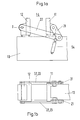
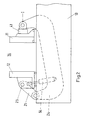
- Figures 1 to 4 each show a machine bed 13 with a Tool locking device 14, which has a fixed tool platen 11 and a movable platen 12 and a pair of toggle levers with one first connecting rod 21 and a second connecting rod 22. As far as the top views are shown a second pair of toggle levers with a first connecting rod 31 and a second connecting rod 32 shown.
- Figure 1 is the first connecting rod 21 with the 'fixed platen 11, in Figures 2 to 3 with the movable platen 12 connected.
- the second connecting rod 22, 32 is designed as a bracket 23, 33.
- the bracket 33 has the basic shape of a bracket with bolts or shafts on the joints.
- the drive of the pair of toggle levers is a piston-cylinder unit 54, which is located on the Machine bed supported and attached to the second connecting rod 22.
- the second connecting rod 24 is configured in a C-shape.
- a piston-cylinder unit 54 is connected to the first connecting rod 21.
- a spacer 41 is arranged, here designed as a short-stroke cylinder, the hydraulic drive device is not shown.
- Figure 3 is between the second connecting rod 24 and the fixed one Tool clamping plate 11 and a lifting device 42 in addition to the spacer 41 arranged for setting the tool heights.
- a rotary drive 53 is used as the drive unit Shaft 25 is connected to the first connecting rod 21.
- the total stroke H is shown, which is the basic dimension for a Eccentricity e when using the shaft 25 serves as an eccentric 26.
- the spacer 41 can be omitted become.
- a linear force unit 51 in the form of a spindle is used as the drive unit 52 was chosen.
- the first connecting rod 21 is designed as a piston-cylinder unit 54. Especially the articulated connection between the second can be done in a simple manner Design the connecting rod 24 and the fixed platen 11 constructively.
Landscapes
- Engineering & Computer Science (AREA)
- Mechanical Engineering (AREA)
- Manufacturing & Machinery (AREA)
- Moulds For Moulding Plastics Or The Like (AREA)
- Injection Moulding Of Plastics Or The Like (AREA)
Claims (10)
- Machine de coulée par injection comportant une unité de fermeture d'outil, qui présente une plaque de serrage d'outil fixe et une plaque de serrage d'outil mobile et actionnée par un levier coudé,
caractérisée en ce que le dispositif de fermeture d'outil (14) possède au moins une paire de leviers coudés (21, 22), dont la première bielle (21) est reliée de façon pivotante à la plaque de serrage d'outil fixe (11) et dont la seconde bielle (22) est reliée de façon pivotante à la plaque de serrage d'outil mobile (12), et en ce qu'il est prévu une unité d'entraínement (51, 52, 54), qui est reliée à une des bielles de la paire de leviers coudés (21, 22) pour ouvrir et fermer le moule. - Machine de coulée par injection selon la revendication 1,
caractérisée en ce qu'au moins une des bielles (21, 22) est réalisée en forme de C (24) et entoure les plaques de serrage d'outil (11 ou 12) et est guidée jusque dans la zone de l'axe central (I). - Machine de coulée par injection selon la revendication 1,
caractérisée en ce qu'une bielle (21, 31) est réalisée comme étrier (23) qui entoure la plaque de serrage d'outil fixe (11) et la plaque de serrage d'outil mobile (12). - Machine de coulée par injection selon une des revendications précédentes,
caractérisée en ce que, entre l'extrémité de tête d'une bielle (21, 22) et une plaque de serrage d'outil (11, 12), il est agencé un écarteur (41) de longueur réglable. - Machine de coulée par injection selon la revendication 4,
caractérisée en ce que l'écarteur (4) peut être entraíné de façon hydraulique ou électrique et est réglable à une longueur (L) qui est au moins nécessaire pour engendrer la force de fermeture. - Machine de coulée par injection selon la revendication 5 ou 1,
caractérisée en ce qu'un dispositif de levage (42) est prévu, qui est relié à une des bielles (21, 22) et à une des plaques de serrage d'outil (11, 12), et comporte des pièces grâce auxquelles la hauteur de l'outil (W) est réglable. - Machine de coulée par injection selon la revendication 6,
caractérisée en ce que l'écarteur (41) et le dispositif de levage (42) forment, au niveau constructif et fonctionnel, une unité. - Machine de coulée par injection selon une des revendications précédentes,
caractérisée en ce que l'unité d'entraínement est un entraínement en rotation (53), qui est raccordé à un arbre (25) relié à une des bielles (21, 22), par exemple un entraínement en rotation présentant un moteur électrique. - Machine de coulée par injection selon une des revendications précédentes,
caractérisée en ce que l'unité d'entraínement est une unité de force (51) linéairement mobile, reliée à une des bielles (21, 22), par exemple un vérin hydraulique (54) ou un axe (52) électriquement déplaçable. - Machine de coulée par injection selon une des revendications précédentes,
caractérisée en ce qu'un des arbres de bielle (25) est réalisé comme excentrique (26) et est relié à un entraínement en rotation (53).
Applications Claiming Priority (2)
| Application Number | Priority Date | Filing Date | Title |
|---|---|---|---|
| DE19643366A DE19643366C2 (de) | 1996-10-09 | 1996-10-09 | Spritzgießmaschine mit einer Werkzeugschließeinrichtung |
| DE19643366 | 1996-10-09 |
Publications (2)
| Publication Number | Publication Date |
|---|---|
| EP0835733A1 EP0835733A1 (fr) | 1998-04-15 |
| EP0835733B1 true EP0835733B1 (fr) | 2001-07-11 |
Family
ID=7809321
Family Applications (1)
| Application Number | Title | Priority Date | Filing Date |
|---|---|---|---|
| EP97250291A Expired - Lifetime EP0835733B1 (fr) | 1996-10-09 | 1997-09-25 | Presse d'injection avec un dispositif de fermeture |
Country Status (4)
| Country | Link |
|---|---|
| US (1) | US6312249B1 (fr) |
| EP (1) | EP0835733B1 (fr) |
| AT (1) | ATE202969T1 (fr) |
| DE (2) | DE19643366C2 (fr) |
Cited By (1)
| Publication number | Priority date | Publication date | Assignee | Title |
|---|---|---|---|---|
| DE102004037357A1 (de) * | 2004-07-30 | 2006-03-23 | Demag Ergotech Gmbh | Schließeinheit für eine Spritzgießmaschine |
Families Citing this family (9)
| Publication number | Priority date | Publication date | Assignee | Title |
|---|---|---|---|---|
| DE19957485A1 (de) | 1999-11-23 | 2001-05-31 | Mannesmann Ag | Spritzgiessmaschine mit Linearmotor |
| AT410423B (de) * | 2000-06-21 | 2003-04-25 | Engel Gmbh Maschbau | Spritzgiessmaschine |
| DE10102464C1 (de) * | 2001-01-12 | 2002-07-11 | Mannesmann Plastics Machinery | Formmaschine |
| ATA10352001A (de) * | 2001-07-04 | 2004-10-15 | Engel Austria Gmbh | Spritzgiessmaschine mit einer ortsfesten und einer bewegbaren formaufspannplatte |
| DE10141277A1 (de) * | 2001-08-23 | 2003-03-13 | Demag Ergotech Gmbh | Schließeinrichtung für eine Spritzgießmaschine oder Presse |
| DE102009034176B3 (de) * | 2009-07-22 | 2010-08-26 | Kraussmaffei Technologies Gmbh | Schließeinheit für eine Spritzgießmaschine |
| JP5946788B2 (ja) | 2012-05-24 | 2016-07-06 | 住友重機械工業株式会社 | 射出成形機 |
| CN105383024B (zh) * | 2015-12-15 | 2017-12-26 | 张忠信 | 用于压铸机或注塑机的万向合模机构 |
| CN112622119B (zh) * | 2020-12-01 | 2022-06-17 | 中山晔丽灯饰有限公司 | 一种led灯具的加工机构 |
Family Cites Families (14)
| Publication number | Priority date | Publication date | Assignee | Title |
|---|---|---|---|---|
| US2233354A (en) * | 1936-03-23 | 1941-02-25 | Eckert & Ziegler Gmbh | Injection molding machine |
| DE1704064C3 (de) * | 1968-02-12 | 1975-08-14 | Erlenbach Gmbh & Co, 5429 Lautert | Vorrichtung zum Schließen von trennbaren Formteilen, insbesondere Schäumformen für Kunststoff |
| US3768952A (en) * | 1971-08-24 | 1973-10-30 | Sund Borg Machines Corp | Mold clamp |
| DE2146245C3 (de) * | 1971-09-16 | 1975-09-04 | Desma-Werke Gmbh, 2807 Uesen | Formwerkzeuge, Insbesondere zum Herstellen von Formungen aus Polyurethan |
| ES411013A1 (es) * | 1972-01-31 | 1975-12-01 | Kautex Werke Gmbh | Un dispositivo para la fabricacion de cuerpos huecos, en particular botellas, cajas o similares, de material sinteti-co termoplastico por el procedimiento de soplado. |
| DE2545130C3 (de) * | 1975-10-08 | 1980-06-26 | Gildemeister Corpoplast Gmbh, 2000 Hamburg | Vorrichtung zum Blasformen eines Behälters |
| IT1156405B (it) * | 1978-01-09 | 1987-02-04 | Enrietti Sas Di L & P Enrietti | Pressa per lo stampaggio di materiali plastici |
| DE2940114C2 (de) * | 1979-10-03 | 1984-03-15 | Krauss-Maffei AG, 8000 München | Vorrichtung zum Formen von Gegenständen |
| US5104308A (en) * | 1990-03-08 | 1992-04-14 | Morton Ray H | Mold plate control mechanism for a multiple plate mold |
| IL100832A (en) * | 1992-01-31 | 1994-01-25 | Ziv Av Amir | Clamping assembly for an injection moulding apparatus |
| DE4308962C2 (de) * | 1993-03-20 | 1995-07-27 | Karl Hehl | Formschließeinheit für eine Spritzgießmaschine |
| DE4313472C2 (de) * | 1993-04-24 | 1996-10-24 | Karl Hehl | Formschließeinheit für eine Kunststoff-Spritzgießmaschine |
| DE4411649C2 (de) * | 1993-09-30 | 1997-10-02 | Karl Hehl | Schließeinheit für Formen zum Herstellen von Gegenständen aus plastifizierbaren Massen |
| AT402276B (de) * | 1994-08-31 | 1997-03-25 | Engel Gmbh Maschbau | Schliesseinheit einer spritzgiessmaschine |
-
1996
- 1996-10-09 DE DE19643366A patent/DE19643366C2/de not_active Expired - Lifetime
-
1997
- 1997-09-25 EP EP97250291A patent/EP0835733B1/fr not_active Expired - Lifetime
- 1997-09-25 AT AT97250291T patent/ATE202969T1/de not_active IP Right Cessation
- 1997-09-25 DE DE59704003T patent/DE59704003D1/de not_active Expired - Fee Related
- 1997-10-03 US US08/943,734 patent/US6312249B1/en not_active Expired - Lifetime
Cited By (1)
| Publication number | Priority date | Publication date | Assignee | Title |
|---|---|---|---|---|
| DE102004037357A1 (de) * | 2004-07-30 | 2006-03-23 | Demag Ergotech Gmbh | Schließeinheit für eine Spritzgießmaschine |
Also Published As
| Publication number | Publication date |
|---|---|
| DE19643366A1 (de) | 1998-04-16 |
| US6312249B1 (en) | 2001-11-06 |
| ATE202969T1 (de) | 2001-07-15 |
| DE59704003D1 (de) | 2001-08-16 |
| EP0835733A1 (fr) | 1998-04-15 |
| DE19643366C2 (de) | 2000-05-18 |
Similar Documents
| Publication | Publication Date | Title |
|---|---|---|
| EP0722820B1 (fr) | Dispositif de fermeture de moule sans colonnes | |
| EP0835733B1 (fr) | Presse d'injection avec un dispositif de fermeture | |
| WO1995004643A1 (fr) | Machine de moulage par injection | |
| EP0456335B1 (fr) | Dispositif pour fermer les moules d'une machine à mouler par injection | |
| EP0626245B1 (fr) | Unité de fermeture de moule pour une machine à mouler par injection les matières plastiques | |
| EP1273423B1 (fr) | Plaque de fixation de moule pour une presse à injecter | |
| EP0646448B1 (fr) | Machine à mouler par injection pour traiter des matières plastifiables | |
| EP0620095B1 (fr) | Machine à mouler par injection | |
| EP0770468A2 (fr) | Machine à mouler par injection sans colonnes à deux plateaux | |
| EP0933181A2 (fr) | Dispositif de fermeture de moules pour la fabrication d'objets en résine thermoplastique | |
| DE69523775T2 (de) | Spritzgiessmaschine mit offenem rahmen | |
| EP1765566B1 (fr) | Unite de fermeture de moule | |
| DE3933348C2 (fr) | ||
| DE4320366C2 (de) | Formschließeinheit für eine Kunststoff-Spritzgießmaschine | |
| AT524560B1 (de) | Schließeinheit für eine Formgebungsmaschine und Formgebungsmaschine mit einer solchen | |
| DE4411649C2 (de) | Schließeinheit für Formen zum Herstellen von Gegenständen aus plastifizierbaren Massen | |
| AT526987B1 (de) | Anordnung aus einer Formaufspannplatte für eine Formgebungsmaschine und zumindest einer Verriegelungsvorrichtung | |
| DE1960948A1 (de) | Maschine zum Formen von Kunststoffen und anderen verpressbaren Massen | |
| EP0783955B1 (fr) | Machine de moulage par injection à deux plateaux avec un plateau mobile et un plateau fixe | |
| EP0161643B1 (fr) | Dispositif pour l'éjection des pièces estampées de la matrice dans une presse de formage | |
| DE29513862U1 (de) | Schließeinheit einer Spritzgießmaschine | |
| DE19847306C1 (de) | Vorrichtung zum Anpassen einer Kunststoffverarbeitungsmaschine, insbesondere Blasformmaschine, an unterschiedliche Formdicken | |
| EP1285739A2 (fr) | Dispositif de fermeture pour une machine à mouler par injection ou presse | |
| EP0689924A1 (fr) | Unité de fermeture sans colonnes pour une machine destinée à la transformation de matière injectables | |
| DE102022122910A1 (de) | Schließeinheit und Formgebungsmaschine mit einer solchen |
Legal Events
| Date | Code | Title | Description |
|---|---|---|---|
| PUAI | Public reference made under article 153(3) epc to a published international application that has entered the european phase |
Free format text: ORIGINAL CODE: 0009012 |
|
| 17P | Request for examination filed |
Effective date: 19980205 |
|
| AK | Designated contracting states |
Kind code of ref document: A1 Designated state(s): AT CH DE FR GB IT LI NL |
|
| AKX | Designation fees paid |
Free format text: AT CH DE FR GB IT LI NL |
|
| RBV | Designated contracting states (corrected) |
Designated state(s): AT CH DE FR GB IT LI NL |
|
| GRAG | Despatch of communication of intention to grant |
Free format text: ORIGINAL CODE: EPIDOS AGRA |
|
| GRAG | Despatch of communication of intention to grant |
Free format text: ORIGINAL CODE: EPIDOS AGRA |
|
| GRAH | Despatch of communication of intention to grant a patent |
Free format text: ORIGINAL CODE: EPIDOS IGRA |
|
| 17Q | First examination report despatched |
Effective date: 20001215 |
|
| RAP1 | Party data changed (applicant data changed or rights of an application transferred) |
Owner name: ATECS MANNESMANN AG |
|
| GRAH | Despatch of communication of intention to grant a patent |
Free format text: ORIGINAL CODE: EPIDOS IGRA |
|
| RAP1 | Party data changed (applicant data changed or rights of an application transferred) |
Owner name: DEMAG-ERGOTECH GMBH |
|
| GRAA | (expected) grant |
Free format text: ORIGINAL CODE: 0009210 |
|
| AK | Designated contracting states |
Kind code of ref document: B1 Designated state(s): AT CH DE FR GB IT LI NL |
|
| REF | Corresponds to: |
Ref document number: 202969 Country of ref document: AT Date of ref document: 20010715 Kind code of ref document: T |
|
| REG | Reference to a national code |
Ref country code: CH Ref legal event code: NV Representative=s name: E. BLUM & CO. PATENTANWAELTE Ref country code: CH Ref legal event code: EP |
|
| GBT | Gb: translation of ep patent filed (gb section 77(6)(a)/1977) |
Effective date: 20010711 |
|
| REF | Corresponds to: |
Ref document number: 59704003 Country of ref document: DE Date of ref document: 20010816 |
|
| ITF | It: translation for a ep patent filed | ||
| ET | Fr: translation filed | ||
| REG | Reference to a national code |
Ref country code: GB Ref legal event code: IF02 |
|
| PLBE | No opposition filed within time limit |
Free format text: ORIGINAL CODE: 0009261 |
|
| STAA | Information on the status of an ep patent application or granted ep patent |
Free format text: STATUS: NO OPPOSITION FILED WITHIN TIME LIMIT |
|
| 26N | No opposition filed | ||
| PGFP | Annual fee paid to national office [announced via postgrant information from national office to epo] |
Ref country code: GB Payment date: 20030827 Year of fee payment: 7 |
|
| PGFP | Annual fee paid to national office [announced via postgrant information from national office to epo] |
Ref country code: NL Payment date: 20030828 Year of fee payment: 7 |
|
| PG25 | Lapsed in a contracting state [announced via postgrant information from national office to epo] |
Ref country code: GB Free format text: LAPSE BECAUSE OF NON-PAYMENT OF DUE FEES Effective date: 20040925 |
|
| PG25 | Lapsed in a contracting state [announced via postgrant information from national office to epo] |
Ref country code: NL Free format text: LAPSE BECAUSE OF NON-PAYMENT OF DUE FEES Effective date: 20050401 |
|
| GBPC | Gb: european patent ceased through non-payment of renewal fee |
Effective date: 20040925 |
|
| NLV4 | Nl: lapsed or anulled due to non-payment of the annual fee |
Effective date: 20050401 |
|
| PGFP | Annual fee paid to national office [announced via postgrant information from national office to epo] |
Ref country code: CH Payment date: 20060914 Year of fee payment: 10 Ref country code: AT Payment date: 20060914 Year of fee payment: 10 |
|
| PGFP | Annual fee paid to national office [announced via postgrant information from national office to epo] |
Ref country code: FR Payment date: 20060922 Year of fee payment: 10 |
|
| PGFP | Annual fee paid to national office [announced via postgrant information from national office to epo] |
Ref country code: IT Payment date: 20060930 Year of fee payment: 10 |
|
| PGFP | Annual fee paid to national office [announced via postgrant information from national office to epo] |
Ref country code: DE Payment date: 20070921 Year of fee payment: 11 |
|
| REG | Reference to a national code |
Ref country code: CH Ref legal event code: PFA Owner name: DEMAG-ERGOTECH GMBH Free format text: DEMAG-ERGOTECH GMBH#ALTDORFER STRASSE 15#90571 SCHWAIG (DE) -TRANSFER TO- DEMAG-ERGOTECH GMBH#ALTDORFER STRASSE 15#90571 SCHWAIG (DE) |
|
| REG | Reference to a national code |
Ref country code: CH Ref legal event code: PL |
|
| PG25 | Lapsed in a contracting state [announced via postgrant information from national office to epo] |
Ref country code: AT Free format text: LAPSE BECAUSE OF NON-PAYMENT OF DUE FEES Effective date: 20070925 |
|
| PG25 | Lapsed in a contracting state [announced via postgrant information from national office to epo] |
Ref country code: LI Free format text: LAPSE BECAUSE OF NON-PAYMENT OF DUE FEES Effective date: 20070930 Ref country code: CH Free format text: LAPSE BECAUSE OF NON-PAYMENT OF DUE FEES Effective date: 20070930 |
|
| REG | Reference to a national code |
Ref country code: FR Ref legal event code: ST Effective date: 20080531 |
|
| PG25 | Lapsed in a contracting state [announced via postgrant information from national office to epo] |
Ref country code: FR Free format text: LAPSE BECAUSE OF NON-PAYMENT OF DUE FEES Effective date: 20071001 |
|
| PG25 | Lapsed in a contracting state [announced via postgrant information from national office to epo] |
Ref country code: IT Free format text: LAPSE BECAUSE OF NON-PAYMENT OF DUE FEES Effective date: 20070925 Ref country code: DE Free format text: LAPSE BECAUSE OF NON-PAYMENT OF DUE FEES Effective date: 20090401 |