EP0835737B1 - Procédé et dispositif pour le moulage par injection-étirage-soufflage - Google Patents
Procédé et dispositif pour le moulage par injection-étirage-soufflage Download PDFInfo
- Publication number
- EP0835737B1 EP0835737B1 EP97117409A EP97117409A EP0835737B1 EP 0835737 B1 EP0835737 B1 EP 0835737B1 EP 97117409 A EP97117409 A EP 97117409A EP 97117409 A EP97117409 A EP 97117409A EP 0835737 B1 EP0835737 B1 EP 0835737B1
- Authority
- EP
- European Patent Office
- Prior art keywords
- preforms
- numbers
- injection
- blow molding
- supporting members
- Prior art date
- Legal status (The legal status is an assumption and is not a legal conclusion. Google has not performed a legal analysis and makes no representation as to the accuracy of the status listed.)
- Expired - Lifetime
Links
- 238000010103 injection stretch blow moulding Methods 0.000 title claims description 35
- 238000000034 method Methods 0.000 title description 7
- 238000000071 blow moulding Methods 0.000 claims description 54
- 238000001746 injection moulding Methods 0.000 claims description 54
- 238000002347 injection Methods 0.000 claims description 50
- 239000007924 injection Substances 0.000 claims description 50
- 238000001816 cooling Methods 0.000 claims description 44
- 230000003028 elevating effect Effects 0.000 description 28
- 210000003739 neck Anatomy 0.000 description 27
- 238000010438 heat treatment Methods 0.000 description 13
- 238000010276 construction Methods 0.000 description 2
- 239000000498 cooling water Substances 0.000 description 2
- 238000010586 diagram Methods 0.000 description 2
- 238000010102 injection blow moulding Methods 0.000 description 2
- 238000000465 moulding Methods 0.000 description 2
- 230000002829 reductive effect Effects 0.000 description 2
- 239000012858 resilient material Substances 0.000 description 2
- 230000000452 restraining effect Effects 0.000 description 2
- 238000006243 chemical reaction Methods 0.000 description 1
- 239000012530 fluid Substances 0.000 description 1
- 230000000670 limiting effect Effects 0.000 description 1
- 230000036961 partial effect Effects 0.000 description 1
- 230000002441 reversible effect Effects 0.000 description 1
- 238000000926 separation method Methods 0.000 description 1
Images





Classifications
-
- B—PERFORMING OPERATIONS; TRANSPORTING
- B29—WORKING OF PLASTICS; WORKING OF SUBSTANCES IN A PLASTIC STATE IN GENERAL
- B29C—SHAPING OR JOINING OF PLASTICS; SHAPING OF MATERIAL IN A PLASTIC STATE, NOT OTHERWISE PROVIDED FOR; AFTER-TREATMENT OF THE SHAPED PRODUCTS, e.g. REPAIRING
- B29C49/00—Blow-moulding, i.e. blowing a preform or parison to a desired shape within a mould; Apparatus therefor
- B29C49/42—Component parts, details or accessories; Auxiliary operations
- B29C49/4205—Handling means, e.g. transfer, loading or discharging means
- B29C49/42113—Means for manipulating the objects' position or orientation
- B29C49/42115—Inversion, e.g. turning preform upside down
-
- B—PERFORMING OPERATIONS; TRANSPORTING
- B29—WORKING OF PLASTICS; WORKING OF SUBSTANCES IN A PLASTIC STATE IN GENERAL
- B29C—SHAPING OR JOINING OF PLASTICS; SHAPING OF MATERIAL IN A PLASTIC STATE, NOT OTHERWISE PROVIDED FOR; AFTER-TREATMENT OF THE SHAPED PRODUCTS, e.g. REPAIRING
- B29C35/00—Heating, cooling or curing, e.g. crosslinking or vulcanising; Apparatus therefor
- B29C35/02—Heating or curing, e.g. crosslinking or vulcanizing during moulding, e.g. in a mould
- B29C35/08—Heating or curing, e.g. crosslinking or vulcanizing during moulding, e.g. in a mould by wave energy or particle radiation
- B29C35/0805—Heating or curing, e.g. crosslinking or vulcanizing during moulding, e.g. in a mould by wave energy or particle radiation using electromagnetic radiation
- B29C2035/0822—Heating or curing, e.g. crosslinking or vulcanizing during moulding, e.g. in a mould by wave energy or particle radiation using electromagnetic radiation using IR radiation
-
- B—PERFORMING OPERATIONS; TRANSPORTING
- B29—WORKING OF PLASTICS; WORKING OF SUBSTANCES IN A PLASTIC STATE IN GENERAL
- B29C—SHAPING OR JOINING OF PLASTICS; SHAPING OF MATERIAL IN A PLASTIC STATE, NOT OTHERWISE PROVIDED FOR; AFTER-TREATMENT OF THE SHAPED PRODUCTS, e.g. REPAIRING
- B29C35/00—Heating, cooling or curing, e.g. crosslinking or vulcanising; Apparatus therefor
- B29C35/16—Cooling
- B29C2035/1616—Cooling using liquids
-
- B—PERFORMING OPERATIONS; TRANSPORTING
- B29—WORKING OF PLASTICS; WORKING OF SUBSTANCES IN A PLASTIC STATE IN GENERAL
- B29C—SHAPING OR JOINING OF PLASTICS; SHAPING OF MATERIAL IN A PLASTIC STATE, NOT OTHERWISE PROVIDED FOR; AFTER-TREATMENT OF THE SHAPED PRODUCTS, e.g. REPAIRING
- B29C2949/00—Indexing scheme relating to blow-moulding
- B29C2949/07—Preforms or parisons characterised by their configuration
- B29C2949/0715—Preforms or parisons characterised by their configuration the preform having one end closed
-
- B—PERFORMING OPERATIONS; TRANSPORTING
- B29—WORKING OF PLASTICS; WORKING OF SUBSTANCES IN A PLASTIC STATE IN GENERAL
- B29C—SHAPING OR JOINING OF PLASTICS; SHAPING OF MATERIAL IN A PLASTIC STATE, NOT OTHERWISE PROVIDED FOR; AFTER-TREATMENT OF THE SHAPED PRODUCTS, e.g. REPAIRING
- B29C33/00—Moulds or cores; Details thereof or accessories therefor
- B29C33/02—Moulds or cores; Details thereof or accessories therefor with incorporated heating or cooling means
-
- B—PERFORMING OPERATIONS; TRANSPORTING
- B29—WORKING OF PLASTICS; WORKING OF SUBSTANCES IN A PLASTIC STATE IN GENERAL
- B29C—SHAPING OR JOINING OF PLASTICS; SHAPING OF MATERIAL IN A PLASTIC STATE, NOT OTHERWISE PROVIDED FOR; AFTER-TREATMENT OF THE SHAPED PRODUCTS, e.g. REPAIRING
- B29C49/00—Blow-moulding, i.e. blowing a preform or parison to a desired shape within a mould; Apparatus therefor
- B29C49/02—Combined blow-moulding and manufacture of the preform or the parison
- B29C49/06—Injection blow-moulding
-
- B—PERFORMING OPERATIONS; TRANSPORTING
- B29—WORKING OF PLASTICS; WORKING OF SUBSTANCES IN A PLASTIC STATE IN GENERAL
- B29C—SHAPING OR JOINING OF PLASTICS; SHAPING OF MATERIAL IN A PLASTIC STATE, NOT OTHERWISE PROVIDED FOR; AFTER-TREATMENT OF THE SHAPED PRODUCTS, e.g. REPAIRING
- B29C49/00—Blow-moulding, i.e. blowing a preform or parison to a desired shape within a mould; Apparatus therefor
- B29C49/42—Component parts, details or accessories; Auxiliary operations
- B29C49/64—Heating or cooling preforms, parisons or blown articles
- B29C49/68—Ovens specially adapted for heating preforms or parisons
- B29C49/685—Rotating the preform in relation to heating means
-
- B—PERFORMING OPERATIONS; TRANSPORTING
- B29—WORKING OF PLASTICS; WORKING OF SUBSTANCES IN A PLASTIC STATE IN GENERAL
- B29L—INDEXING SCHEME ASSOCIATED WITH SUBCLASS B29C, RELATING TO PARTICULAR ARTICLES
- B29L2031/00—Other particular articles
- B29L2031/46—Knobs or handles, push-buttons, grips
- B29L2031/463—Grips, handles
Definitions
- the present invention relates to an injection stretch blow molding apparatus according to the preamble of claim 1 and an injection stretch blow molding method according to the preamble of claim 16.
- This known apparatus has an injection molding station in which a preform is injection-molded, a blow molding station in which the preform is stretch blow molded, and a transfer station which transfers preforms from an injection molding station to the blow molding station.
- each preform is cooled by an injection molding core mold, and after the preform has cooled to a temperature at which removal is possible, the preform is removed from the injection core mold by a removal section.
- the plurality of simultaneously injection-molded preforms are, either in a single operation or divided into a plurality of operations, delivered toa blow molding station.
- a receiving mechanism which receives a plurality of simultaneously molded preforms.
- the preforms are moved linearly in an upright state to an inverting and delivering mechanism which inverts the preforms received by the receiving mechanism from the upright state and, either in a single operation or divided into a plurality of operations, delivers them to the blow molding station.
- preforms received from the transfer station are carried by a carrying member which is circulatingly carried.
- the preforms are carried into a blow molding section in batches numbering fewer than the number of preforms molded simultaneously through a heating section and a standby section, then are blow-molded to containers.
- preforms are molded with a reduced injection molding cycle time while maintaining an adequate cooling time. Moreover, the operating efficiency of the blow cavity mold can be increased.
- the present invention is a further development of this injection stretch blow molding apparatus and method.
- the object of the present invention is to provide an injection stretch blow molding apparatus and method which allows to produce containers of high quality even out of thick preforms.
- the circulatory movement means functions as a buffer, and more time can be taken between removing the preforms from the injection molding station and delivering them to the blow molding station.
- this allows the temperature difference between the inner and outer walls to be minimized, and provides time for gentle cooling, thus reducing the unfavorable influence at the time of blow molding caused by the temperature distribution applied to the preform during the injection molding process.
- the receiving mechanism can be returned to the receiving position ming for removing preforms from the injection molding station is increased.
- the receiving mechanism preferably has N numbers of first or receipt supporting members for receiving and supporting N (N ⁇ 2) numbers of preforms simultaneously injection molded in the injection molding station. Furthermore, the movement mechanism preferably has at least N second supporting members.
- the N number of preforms simultaneously injection molded can be transferred from the receiving mechanism to the movement mechanism in a single operation.
- the blow molding station has a blow molding section for blow molding n (1 ⁇ n ⁇ N) number of the preforms into n number of containers at a time; and wherein the inverting and delivering mechanism preferably has n number of third or invert supporting member inverting and delivering the same n number of the preforms as are to be simultaneously blow molded by the blow molding station. If N number of preforms are delivered simultaneously, the number of the third supporting members is increased. Therefore, by delivering a number n appropriate to the blow molding cycle, the number of the third supporting members can be reduced. It should be noted that the time required for delivery in this way is increased. Nevertheless, since the receiving mechanism is not involved in the delivery operation, and the receiving mechanism can be immediately returned to the receiving position.
- the movement mechanism preferably has a circulatory movement means circulating and moving at least N numbers of second supporting members. This makes easy the movement of the second supporting members from the receiving position from the receiving mechanism to the delivery position leading to the inverting and delivering mechanism.
- the circulatory movement means preferably have a first endless moving member circulating in a vertical plane, and at least N numbers of second supporting members fixed thereto. In this way, the space required for the circulatory movement means can be kept to a minimum. It should be noted that if the first endless moving member has an upper movement region provided with the receiving position and the delivering position, the preform can be transferred in the upright state.
- the circulatory movement means may also have a second endless moving member circulating in the horizontal plane, and at least N numbers of second supporting members fixed thereto.
- the second endless moving member may have first and second movement regions mutually parallel in the horizontal plane, and a large number of preforms can be transferred in the upright state.
- the ability of the circulatory movement means to function as a buffer is increased, and a longer cooling time is available.
- Each of the N numbers of second supporting members preferably has a depression receiving and supporting the bottom of the preforms in the upright state.
- Each of at least the N numbers of second supporting members may have a pair of opening and closing members biased toward the closed position by a resilient member. This pair of opening and closing members supports a portion under the neck portion of the preform. In this way, the support and removal operations on the preform may be simplified.
- the injection molding station may have:
- the preforms can be cooled from the outside by the cooling pots in the removal section, and in particular the cooling efficiency for thick preforms can be further increased.
- Fig. 1 is a plan view of an injection stretch blow molding apparatus being an embodiment of the present invention.
- Fig. 2 is an enlarged plan view of the transfer station of Fig. 1.
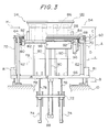
- Fig. 3 is a front elevation of the receiving mechanism of Fig. 2.
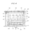
- Fig. 4 is a rear elevation of the movement mechanism of Fig. 2.
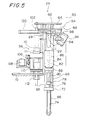
- Fig. 5 is a side elevation of the receiving mechanism and movement mechanism.
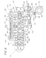
- Fig. 6 is a side elevation of the movement mechanism and inverting and delivering mechanism.
- Fig. 7 is a process diagram showing the operation of the receiving mechanism from the cooling of a preform by a cooling pot, receiving the preform and delivering the same to the movement mechanism.
- Fig. 8 is a plan view showing another embodiment of the transfer station.
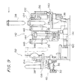
- Fig. 9 is a side elevation of the transfer station of Fig. 8.
- Fig. 10 is a schematic diagram showing the process of the present invention.
- Figs. 1 to 7 show an injection stretch blow molding apparatus being an embodiment of the present invention.
- Fig. 1 is a plan view of the injection stretch blow molding apparatus.
- This injection stretch blow molding apparatus has provided on a machine base 10 in broad outline an injection molding station 12, a blow molding station 14, and a transfer station 16 positioned between the injection molding station 12 and blow molding station 14.
- the injection molding station 12 has two injection core molds (not shown in the drawings) which are disposed by 180 degrees apart, and a turntable 18 which intermittently circulates the injection core molds along a rotary carrying path.
- the injection molding station 12 also comprises an injection molding section 22 which is provided opposite to an injection molding apparatus 20, and a removal section 24 is provided opposite to the injection molding section 22. Each of the injection core molds is stopped at the injection molding section 22 or the removal section 24.
- the injection molding section 22 has an injection cavity mold 26 which can be clamped with respect to each of the injection core molds, and simultaneously injection-molds for example four preforms 28 (see Figs. 2 to 7).
- the injection molding section 22 is such that, as shown for example in Fig. 2, preforms 28 are injection-molded with integral handles 29.
- the injection core molds are released relative to the preforms 28, so that the preforms 28 can be removed from the injection core molds.
- the neck portion of the preforms 28 is molded by a neck cavity mold (not shown in the drawings), and the preforms 28 are supported by the neck cavity molds and injection core molds and carried by the turntable 18 to the removal section 24.
- the preform 28 can be removed by releasing the preforms 28 from the neck cavity molds after partial releasing from the injection core molds.
- the blow molding station 14 has a carrying means 34 comprising four sprockets 30, a carrying chain 32 passed around four sprockets, and a device for driving the sprockets (not shown) such as an electric motor driving one of the sprockets or a pinion attached to a sprocket and to a rack attached to a hydraulic cylinder.
- a carrying means 34 comprising four sprockets 30, a carrying chain 32 passed around four sprockets, and a device for driving the sprockets (not shown) such as an electric motor driving one of the sprockets or a pinion attached to a sprocket and to a rack attached to a hydraulic cylinder.
- the carrying chain has a plurality of for example twelve carrying members 36 fixedly connected thereto and spaced at equal intervals.
- the preforms 28 or containers 38 are supported by each of the carrying members 36.
- an receiving section 40 which receives preforms 28 from the transfer station 16
- a heating section 42 which heats preforms 28 received by the receiving section 40 to at least a temperature appropriate to blow molding
- a blow molding section 44 which stretch blow molds preforms 28 heated at the heating section 42 into containers 38
- a container removal section 46 for removing the containers 38 blow-molded at the blow molding section 44 from the apparatus.
- a heating device 43 is disposed in the heating section 42.
- the heating device 43 may include a plurality of infrared heaters extending along the carrying path and disposed one above another. As the preforms are moved through the heating device 43, the sprockets provided on the carrying members 36 engage with the preform rotation chain, and rotate the preforms to be heated uniformly around the circumferential direction.
- the blow molding section 44 has a blow cavity mold 48 clamped against the preform 28 by a blow mold clamping mechanism 45, and may blow mold a single preform 28.
- the container removal section 46 includes a removal device 47 for inverting a container 38 into an upright state in which the container 38 is removed from the system.
- a standby section 49 in which the preform 28 which is heated by the heating section 42 is temporarily put on standby.
- the transfer station 16 delivers preforms 28 from the removal section 24 of the injection molding station 12 to the receiving section 40 of the blow molding station 14.
- the transfer station 16 may deliver for example four preforms 28 simultaneously removed at the removal section 24 to the receiving section 40 one at a time.
- the preforms 28 are injection-molded in the upright state
- the transfer station 16 the preforms 28 are inverted and delivered to the blow molding station 14 in the inverted state.
- the preforms 28 with handle 29 which are injection-molded in the injection molding section 22 of the injection molding station 12 are rotatably carried around the rotating shaft 50 of a turntable (not shown in the drawings) to the removal section 24.
- the preforms 28 are cooled by a cooling pot 84 before the preforms 28 are removed from the injection core mold.
- the transfer station 16 After cooling by the cooling pot 84, in the transfer station 16 the preforms 28 are delivered to carrying members 36 attached to the carrying chain 32 of the blow molding station 14.
- the transfer station 16 comprises a receiving mechanism 54, a movement mechanism 56, and an inverting and delivering mechanism 58, and the cooling pot 84 is incorporated within the receiving mechanism 54.
- the receiving mechanism 54 has a fixing frame 64 supported by support pillars 62 on the base 10, and a lower movable frame 66 and upper movable frame 68 are mounted on the support pillars 62 so as to be slidable in the vertical direction.
- the upper movable frame 68 is urged upward by urging members 60 attached to the fixing frame 64, and has push-down rods 70 attached to the lower movable frame 66 passed through, and is able to be engaged with a separation of the distance C from the ends of the push-down rods 70.
- a first elevating cylinder fixing plate 72 is fixed by means of a linking rod 65 (see Fig. 5), and this first elevating cylinder fixing plate 72 has attached two first elevating cylinders 74; two bottom supporting members 80 supporting the bottom of a preform 28 through support plates 78 at the ends of elevating rods 76 of these first elevating cylinders 74, pass through the lower movable frame 66 and are able to move vertically. These bottom supporting members 80 are able to be moved vertically through the distance D by the first elevating cylinders 74.
- the lower movable frame 66 is able to be moved through the distance B by the second elevating cylinders 81 disposed at both ends thereof.
- a cooling pot stand 82 is supported by the support pillars 62 so as to be movable vertically, and on this cooling pot stand 82 is fixed a cooling pot 84.
- the cooling pot 84 has a plurality of for example four cooling depressions 86 which have substantially the same internal shape as the external shape of the preforms 28, and around these depressions are passages (not shown in the drawings) through which is circulated cooling water at between 10 and 20 degrees C the same as the injection mold.
- cooling pot 84 is able to be moved vertically through the distance A by a cooling pot elevating cylinder 88 being an elevating means between the cooling position H1 of the preforms 28 in the removal section 24 at the time of clamping the injection mold and a retracted position H2 when the preforms 28 are being transferred.
- the cooling pot elevating cylinder 88 is fixed to the lower movable frame 66, and an elevating rod 90 thereof is fixed to the cooling pot stand 82; in the raised position the cooling pot 84 contacts a neck cavity mold 122 which holds the necks of the preforms 28 in the removal section 24, and is arranged to cool the preforms 28 from the outside.
- the lower surface of the upper movable frame 68 includes a plurality of first or receipt supporting members 94 corresponding to the number of preforms 28.
- the first supporting members 94 are movable from the removal section 24 to the movement mechanism 56 through a pair of guide rails 92.
- Each of the first supporting members 94 is rotatably movable by a supporting member retracting cylinder 96 between a supporting position in the horizontal orientation and a retracted position in the vertical orientation as shown by a broken line.
- the first supporting member 94 can be opened and closed by a supporting member opening and closing mechanism 98, and in the supporting position is able to support the portion under the neck portion of the preforms 28.
- the supporting member opening and closing mechanism 98 may employ a rack and pinion opening and closing means of a well-known type.
- each of the first supporting members 94 is capable of horizontally moving the preforms 28 from the removal section 24 to the upper position of the movement mechanism 56 by means of a horizontal drive cylinder 100.
- a restraining plate 102 attached to the fixing frame 64.
- the movement mechanism 56 allows a movement chain 106 passed around vertically disposed movement sprockets 104 to be rotated intermittently in the vertical plane by means of a rotary actuator 108; to this movement chain 106 are attached for example ten second supporting members 110, and the second supporting members 110 are arranged to be intermittently circulated one at a time so that four of the second supporting members 110 are positioned at the receiving position of preforms 28 from the receiving mechanism 54 and one of the second supporting members 110 is positioned at the receiving position of the inverting and delivering mechanism 58.
- the second supporting members 110 have depressions 111 receiving the bottom and a part of the body of the preforms 28, and move the preforms 28 with the bottoms supported, one at a time to the receiving position of the inverting and delivering mechanism 58.
- the movement mechanism 56 can be raised and lowered by a third elevating cylinder 112, and raising with respect to preforms moved to the upper position of the second supporting members 110 by the first supporting members 94 is arranged to accept the preforms 28, and at this time the restraining plate 102 serves to position the top of the preforms 28.
- the inverting and delivering mechanism 58 has for example one third or invert supporting member 114 disposed opposing the receiving position of the movement mechanism 56.
- the third supporting member 114 can be opened and closed by a supporting member opening and closing mechanism (not shown in the drawings), and, when the second supporting members 110 are in the position of being raised by the third elevating cylinder 112, is able to support the neck portion of a preform 28.
- This supporting member opening and closing mechanism may employ a rack and pinion opening and closing means of a well-known type.
- the third supporting member 114 is able by means of an inverting drive device 116 to rotate through 180 degrees from the movement mechanism 56 to the receiving section 40 of the blow molding station 14, and invert the preforms 28 from the upright state to the inverted state.
- this inverting position is the standby position for delivering preforms 28 to the carrying members 36 in the position of the receiving section 40 of the blow molding station 14.
- the third supporting member 114 is able to be moved horizontally from the side of the movement mechanism 56 to the side of the receiving section 40 of the blow molding station 14 by means of an advance and retract drive device 118, and is able to move to a position above the carrying members 36.
- the inverting and delivering mechanism 58 is provided with a positioning means 119 for the carrying members 36, and when moved to the side of the receiving section 40 by the advance and retract drive device 118, positioning in engagement with the carrying members 36 is achieved.
- the third supporting member 114 is able to be moved vertically by a fourth elevating cylinder 120, and in respect of a preform 28 positioned above the carrying members 36 of the blow molding station 14, by lowering the third supporting member 114, a preform neck portion is inserted into a projecting support portion of the carrying members 36 (not shown in the drawings), and by opening the third supporting member 114, the neck portion of the preform 28 is released, and the delivery is completed.
- preforms are injection-molded in the upright state, and these preforms are rotated through 180 degrees around the rotating shaft 50 and carried to the removal section 24.
- Preforms removed in the removal section 24 are received by the receiving mechanism 54 of the transfer station 16, remaining in the upright state, and are then transferred by the movement mechanism 56 to the inverting and delivering mechanism 58.
- preforms in the upright state are inverted by turning through 180 degrees, and are delivered to the blow molding station in the inverted state.
- the preforms in the inverted state are then blow-molded in the blow molding station 14.
- a plurality of for example four preforms 28 with handles 29 attached are injection-molded, and these preforms 28, supported by the neck cavity mold 122 (see Figs. 3 and 7) and injection core mold 124 (see Fig. 7), are carried by the turntable 18 to the removal section 24.
- the removal section 24 after the preforms 28 are cooled from the outside by the cooling pot 84, for example four preforms 28 taken at the transfer station 16 are delivered to the movement mechanism 56.
- the bottom supporting members 80 are raised by the distance D by the first elevating cylinders 74, and further, the first supporting members 94 are positioned in the retracted position by the supporting member retracting cylinder 96 (see Fig. 7(1)).
- the cooling pot 84 is lowered by the distance A in Fig. 3 from the position H1 at the height of the neck cavity mold 122 clamping to the retracted position H2, thus being retracted.
- the interval of cooling by the cooling pot lies within the injection molding time, that is to say, within the time during which the mold is clamped, and within the range of time such that there is no impediment to transfer of the preforms, any time interval may be used according to the molding conditions corresponding to the product.
- the neck cavity mold 122 is lowered somewhat, and with a part of the injection core mold 124 remaining within the preforms 28, the preforms 28 are released from the injection core mold 124. At this time, the lower ends of the preforms 28 contact the upper ends of the bottom supporting members 80, and are then supported by the bottom supporting members 80 (see Fig. 7(2)).
- the injection core mold remains slightly within the preforms 28, and the preforms 28 are supported at their upper ends by the injection core mold 124, and supported at their lower ends by the bottom supporting members 80, and in this state are prevented from falling over.
- the first supporting members 94 are rotated through 90 degrees from the retracted position to the supporting position, the first supporting members 94 are closed, and the neck portion of the preforms 28 and/or the bottom thereof is supported (see Fig. 7(3)).
- the lower movable frame 66 is lowered by the distance B in Fig. 3.
- the bottom supporting members 80 attached to the lower movable frame 66 are lowered by the distance B in Fig. 3
- the upper movable frame 68 is lowered lagging by the distance C in Fig. 3 until engaging with the push-down rods 70, and as a result of which the first supporting members 94 attached to the upper movable frame 68 are lowered by a distance (B-C), and the bottoms of the preforms 28 and the tips of the bottom supporting members 80 are separated by the distance C in Fig. 3, so that the preforms 28 are movable horizontally (see Fig. 7(4)).
- the plurality of for example four simultaneously injection-molded preforms 28 are simultaneously removed in the removal section 24, are simultaneously received by the receiving mechanism 54 of the transfer station 16, and are simultaneously passed to the movement mechanism 56.
- the second supporting members 110 supporting the simultaneously received, for example four, preforms 28 are moved to the delivery position to the inverting and delivering mechanism 58 one at a time, by the intermittent driving of the movement chain 106 by driving the rotary actuator 108.
- the inverting and delivering mechanism 58 closes the third supporting member 114 and supports the neck portion of the preforms 28 in the receiving position raised by the third elevating cylinder 112; with the second supporting members 110 lowered by means of the third elevating cylinder 112, rotates the third supporting member 114 through 180 degrees by means of the inverting drive device 116, inverting the preforms 28 from the upright state to the inverted state; and waits until the carrying members 36 of the blow molding station 14 are carried and come to a halt in the receiving section 40.
- the third supporting member 114 is moved horizontally to the side of the carrying members 36 by the advance and retract drive device 118, and with the preforms 28 positioned above the carrying members 36, after lowering with the fourth elevating cylinder 120 and inserting in the carrying members the preforms 28, the third supporting member 114 is opened, and the preforms 28 are released, and when the third supporting member 114 has been moved to the standby position, the carrying members 36 become able to carry.
- preforms 28 supported in the inverted state by the carrying members 36 are intermittently carried by the carrying means 34, and passing through the heating device 43 provided in the heating section 42 the preforms are heated to at least the temperature for blow molding, after which before being carried to the blow molding section 44, being put on standby in the standby section 49, evening out of the temperature of the heating by means of the heating section 42 is carried out, after which in the blow molding section 44 blow molding to container shape is carried out.
- Containers 38 with attached handles 29 blow-molded in the blow molding section 44 are carried to the removal section 24, and in the container removal section 46, containers 38 are inverted from the inverted state to the upright state by the removal device 47 and removed.
- Figs. 8 and 9 illustrate another embodiment of the transfer station.
- This transfer station 16 has a receiving mechanism 130 having four first supporting members 134 can be opened and closed by a supporting member opening and closing mechanism 132, the supporting member opening and closing mechanism 132 and first supporting members 134 can be raised and lowered by a pair of first elevating cylinders 136, and by means of these first elevating cylinders 136 the first supporting members 134 are raised to below the neck portion of the preforms 28 in the removal section 24 at the time that the neck cavity mold is lowered, and support below the neck portion, and after unclamping of the neck cavity mold, are arranged to be lowered.
- first supporting members 134, the supporting member opening and closing mechanism 132, and the first elevating cylinders 136 are mounted on a guide member 140 capable of sliding to the side of a movement mechanism 142 on a guide rail 138, and as this guide member 140 is driven by a horizontal drive cylinder 141 the first supporting members 134 are moved toward the side of the movement mechanism 142, and by means of the first supporting members 134 being opened by the supporting member opening and closing mechanism 132 preforms 28 are passed to the movement mechanism 142.
- the movement mechanism 142 has a movement chain 146 passed around horizontally disposed movement sprockets 144, to which are attached for example fourteen second supporting members 148.
- the second supporting members 148 are arranged to be circulated in the horizontal plane.
- the second supporting members 148 are constructed of a resilient material, with two opening and closing jaws 150 urged toward the closed position to support a preform 28 at a bottom position of the neck portion, and when the first supporting members 134 are supporting the preforms 28, the preform 28 is inserted into the opening and closing jaws 150, opposing the urging force of the resilient material to open the opening and closing jaws 150 and dispose the preform 28 between the opening and closing jaws 150.
- the opening and closing jaws 150 are already closed, and when the first supporting members 134 are opened, the preform 28 drops out, and can be handed over supported on the second supporting members 148.
- the second supporting members 148 by means of the movement chain 146, can be carried intermittently one at a time to the delivering position of an inverting receiving mechanism 152.
- the inverting receiving mechanism 152 has the neck portion of the preforms 28 which are supported by the second supporting members 148 in the inverting and delivering position of the movement mechanism 142 seized by a third supporting member 156 which can be opened and closed by an opening and closing mechanism 154.
- this third supporting member 156 is moved horizontally toward the side of the receiving section 40 of the blow molding station 14 by means of an advance and retract drive device 160, whereby the opening and closing jaws 150 of the second supporting members 148 are opened and removal is carried out.
- the third supporting member is raised, and by means of an inverting drive device 155 the third supporting member 156 is turned through 180 degrees, and the preforms 28 are inverted from the upright state to the inverted state, by the lowering by means of the elevating mechanism the preforms are inserted into the carrying members 36 at the position of the receiving section 40, the third supporting member 156 is opened and the preforms 28 are released, and by means of the advance and retract drive device 160 the third supporting member 156 is retracted.
- the inverting receiving mechanism 152 is provided with a positioning means 158 for the carrying members 36, and this positioning means 158, when the third supporting member 156 is moved to the side of the receiving section 40 by the advance and retract drive device 160, is positioned in engagement with the carrying members 36.
- the blow molding is carried out one at a time, as a result of which when carrying out inversion in the inverting receiving mechanism, the items are passed one at a time, but when for example a plurality of preforms are blow-molded simultaneously, a plurality are delivered and it is necessary to convert the pitch spacing between the preforms to the blow molding pitch.
- a conversion means may be used the means described in the abovementioned Japanese Patent Application Laid-Open No. 8-132517.
- the cooling pot in the first described embodiment uses cooling water, but it is possible for the temperature to be controlled to be different in each pot, and depending on the molding conditions a heated fluid may be used.
Landscapes
- Engineering & Computer Science (AREA)
- Manufacturing & Machinery (AREA)
- Mechanical Engineering (AREA)
- Blow-Moulding Or Thermoforming Of Plastics Or The Like (AREA)
- Processing And Handling Of Plastics And Other Materials For Molding In General (AREA)
Claims (22)
- Dispositif de moulage par injection-étirage-soufflage, comprenant:dans lequel ledit poste de transfert (16) comporte:un poste de moulage par injection (12) dans lequel des préformes (28) sont moulées par injection en position debout, des parties de celles-ci formant goulots étant orientées vers le haut;un poste de moulage par soufflage (14) dans lequel des éléments porteurs (36) supportant lesdites préformes (28) sont portés en cercle et lesdites préformes (28) sont moulées par étirage-soufflage sous la forme de récipients (38) en position retournée;un poste de transfert (16), disposé entre ledit poste de moulage par injection (12) et ledit poste de moulage par soufflage (14);caractérisé en ce queun moyen de réception (54) pour recevoir en position debout lesdites préformes (28) provenant dudit poste de moulage par injection (12);un moyen de retournement et d'acheminement (58) pour retourner au moins une à la fois lesdites préformes (28) et acheminer lesdites préformes (28) en position retournée jusqu'auxdits éléments porteurs (36); etun moyen de déplacement (100, 56, 112; 141, 142) disposé entre ledit moyen de réception (54) et ledit moyen d'inversion et d'acheminement (58), et servant à déplacer lesdites préformes (28) en position debout depuis ledit moyen de réception (54) jusqu'audit moyen de retournement et d'acheminement (58),ledit poste de transfert (16) comporte une zone tampon pour lesdites préformes (28),ladite zone tampon est un moyen de déplacement circulatoire, qui comporte un élément de déplacement (106; 146) sans fin, entraíné de manière circulatoire, etune pluralité d'éléments de support (110; 148) pour porter des préformes sont fixés sur ledit élément de déplacement (106; 146) sans fin.
- Dispositif de moulage par injection-étirage-soufflage selon la revendication 1, dans lequel un nombre N (N ≥ 2) desdites préformes (28) sont simultanément moulés par injection dans ledit poste de moulage par injection (12); et
dans lequel ledit moyen de réception (54) a un nombre N d'éléments de support récepteurs (94; 134) pour recevoir et supporter ledit nombre N de préformes (28). - Dispositif de moulage par injection-étirage-soufflage selon la revendication 2,
dans lequel ledit moyen de déplacement (100, 56, 112; 141, 142) a au moins un nombre N d'éléments de support pour supporter et déplacer jusqu'audit moyen de retournement et d'acheminement (58) ledit nombre N de préformes (28) acheminées depuis ledit moyen de réception (54) jusqu'à une position de délivrance. - Dispositif de moulage par injection-étirage-soufflage selon la revendication 2 ou 3,
dans lequel ledit poste de moulage par soufflage (14) a une section de moulage par soufflage (44) pour mouler par soufflage un nombre n (1 ≤ n < N) desdites préformes (28) sous la forme d'un nombre n de récipients (38) à la fois. - Dispositif de moulage par injection-étirage-soufflage selon la revendication 4,
dans lequel ledit moyen de retournement et d'acheminement (58) a un nombre n d'éléments de support à retournement (114, 156) pour recevoir et supporter un nombre n desdites préformes (28) d'au moins un nombre N d'éléments de support (110; 148) et pour retourner et acheminer un nombre n desdites préformes (28). - Dispositif de moulage par injection-étirage-soufflage selon les revendications 2 à 5,
dans lequel ledit moyen de déplacement circulatoire comporte au moins un nombre N d'éléments de support (110; 148). - Dispositif de moulage par injection-étirage-soufflage selon la revendication 2, 4 ou 6,
dans lequel ledit moyen de déplacement (100, 56, 112; 141, 142) comporte ledit moyen de déplacement circulatoire et au moins un nombre N de préformes (28) dans une position de réception en provenance dudit moyen de réception (54) sont déplacées jusqu'à une position de délivrance aboutissant audit moyen de retournement et d'acheminement (58) par l'intermédiaire dudit moyen de déplacement circulatoire. - Dispositif de moulage par injection-étirage-soufflage selon la revendication 2,dans lequel ledit moyen de déplacement circulatoire a un premier élément (106) à mouvement sans fin qui circule dans un plan vertical, au moins un nombre N d'éléments de support (110) étant fixés à celui-ci, dans lequel ledit premier élément (106) à mouvement sans fin a une région supérieure de mouvement et une région inférieure de mouvement, etdans lequel une position de réception et une position de délivrance sont prévues dans ladite région supérieure de mouvement.
- Dispositif de moulage par injection-étirage-soufflage selon la revendication 2,
dans lequel ledit moyen de déplacement circulatoire a un deuxième élément (146) à mouvement sans fin qui circule dans le plan horizontal avec au moins un nombre N d'éléments de support (148) fixés à celui-ci, dans lequel ledit deuxième élément (146) à mouvement sans fin a une première et une deuxième régions de mouvement parallèles l'une à l'autre dans ledit plan horizontal, et dans lequel une position de réception est prévue dans ladite première région de mouvement et une position de délivrance est prévue dans ladite deuxième région de mouvement. - Dispositif de moulage par injection-étirage-soufflage selon l'une quelconque des revendications 2 à 9,
dans lequel chacun desdits au moins un nombre N d'éléments de support (110, 146) a une dépression servant à recevoir et supporter le bas de chacune desdites préformes (28) dans la position debout. - Dispositif de moulage par injection-étirage-soufflage selon l'une quelconque des revendications 2 à 9,
dans lequel chacun desdits au moins un nombre N d'éléments de support (148) a une paire d'éléments d'ouverture et de fermeture (150) poussés dans une direction de fermeture par un élément élastique et ladite paire d'éléments d'ouverture et de fermeture (150) supporte une partie située sous ladite partie formant goulot de chacune desdites préformes (28). - Dispositif de moulage par injection-étirage-soufflage selon l'une quelconque des revendications 2 à 11,
dans lequel ledit moyen de réception (54) comporte un moyen formant élévateur (74; 136) pour lever et abaisser ledit nombre N d'éléments de support récepteurs (94; 134). - Dispositif de moulage par injection-étirage-soufflage selon l'une quelconque des revendications 2 à 12,
dans lequel ledit poste de moulage par injection (12) comporte:dans lequel ladite section d'éjection comporte:deux noyaux d'injection;un élément rotatif (18) qui tourne autour d'un arbre tournant et supporte lesdites deux noyaux d'injection dans des positions mutuellement opposées, ledit arbre tournant étant au centre;une section de moulage par injection (22) comportant une empreinte d'injection (26) verrouillée en alternance avec un desdits deux noyaux d'injection pour mouler par injection un nombre N de préformes (28);ladite section d'éjection pour éjecter ledit nombre N de préformes (28) moulées par injection de l'autre desdits deux noyaux d'injection qui est emporté hors de ladite section de moulage par injection (22) du fait de la rotation dudit élément rotatif, etun nombre N de pots de refroidissement (84) dans lesquels sont insérées un nombre N de préformes (28) supportées par ledit autre des noyaux d'injection; etun moyen formant élévateur pour élever ledit nombre N de pots de refroidissement (84) jusqu'à une position dans laquelle ledit nombre N de préformes (28) sont insérées et pour abaisser ledit nombre N de pots de refroidissement (84) avant que ledit nombre N de préformes (28) ne soient éjectés. - Dispositif de moulage par injection-étirage-soufflage selon la revendication 12,
dans lequel ledit moyen de réception (54) comporte en outre un moyen pour faire reculer ledit nombre N d'éléments de support récepteurs (94; 134) jusqu'à une position qui n'interfère pas avec ledit nombre N de pots de refroidissement (84) dans la position haute de ceux-ci, et pour faire revenir ledit nombre N d'éléments de support récepteurs (94; 134) dans une position permettant de recevoir ledit nombre N de préformes (28) lorsqu'elles sont éjectées. - Dispositif de moulage par injection-étirage-soufflage selon la revendication 1
dans lequel, en outre, des moyens de déplacement (118) sont disposés entre ledit moyen d'inversion et d'acheminement (58) et une partie réceptrice dudit poste de moulage par soufflage (14). - Procédé de moulage par injection-étirage-soufflage, comprenant:caractérisé en ce queune étape de moulage par injection au cours de laquelle des préformes (28) sont moulées par injection en position debout, les parties de celles-ci formant goulots étant orientées vers le haut dans un poste de moulage par injection (12);une étape de moulage par soufflage au cours de laquelle des éléments porteurs (36) supportant lesdites préformes (28) sont portés de manière circulaire et lesdits préformes sont moulées par étirage-soufflage sous la forme de récipients (38) en position retournée dans un poste de moulage par soufflage (14);une étape de transfert pour retourner lesdites préformes (28) retirées dudit poste de moulage par injection (12) et pour transférer lesdites préformes (28) jusqu'auxdits éléments porteurs (36) dudit poste de moulage par soufflage (14); et dans lequel ladite étapes de transfert comporte:une étape de réception au cours de laquelle lesdites préformes (28) moulées par injection dans ledit poste de moulage par injection (12) sont reçues dans ladite position debout par ledit moyen de réception (54);une étape de déplacement au cours de laquelle lesdites préformes (28) acheminées depuis ledit moyen de réception (54) sont déplacées dans ladite position debout par le moyen de déplacement (100, 56, 112; 141, 142); etune étape de retournement et d'acheminement au cours de laquelle lesdites préformes (28) sont retournées au moins une à la fois par le moyen de retournement et d'acheminement (58) et sont acheminées dans ladite position retournée jusqu'auxdits éléments porteurs (36),lors de ladite étape de transfert, lesdites préformes (28) sont déplacées jusqu'à une zone tampon, qui comporte un moyen de déplacement circulatoire ayant un élément de déplacement sans fin (106; 146); etledit élément de déplacement sans fin (106; 146) est entraíné de manière circulatoire et porte lesdites préformes (28) à l'aide d'une pluralité d'éléments de support (110; 148) fixés audit élément de déplacement sans fin (106; 146).
- Procédé de moulage par injection-étirage-soufflage selon la revendication 16,
caractérisé en ce queun nombre N (N ≥ 2) desdites préformes (28) sont simultanément moulées par injection lors de ladite étape de moulage par injection;ledit nombre N de préformes (28) sont reçues par un nombre N d'éléments de support récepteurs (94; 134) lors desdites étapes de réception; etledit nombre N de préformes (28) acheminées depuis lesdits éléments de support récepteurs (94; 134) sont acheminées jusqu'à une position de délivrance jusqu'audit moyen de retournement et d'acheminement (58) à l'aide d'au moins un nombre N d'éléments de support (110, 148) lors de ladite étape de déplacement. - Procédé de moulage par injection-étirage-soufflage selon la revendication 17,
caractérisé en ce queun nombre n (1 ≤ n < N) desdites préformes (28) sont moulées par soufflage pour former un nombre n de récipients (38) à la fois au cours de ladite étape de moulage par soufflage;et ledit n nombre de préformes (28) sont reçues desdits au moins un nombre N d'éléments de support (110; 148) par un nombre n d'éléments de support à retournement (114; 156), et ledit nombre n fe préformes sont retournées et acheminées en même temps au cours de ladite étape de retournement et d'acheminement. - Procédé de moulage par injection-étirage-soufflage selon la revendication 17 ou 18,
caractérisé en ce que
au moins ledit nombre N d'éléments de support (110; 148) ayant reçu ledit nombre n de préformes (28) à la position de réception depuis ledit moyen de réception (54) sont acheminés jusqu'à la position de délivrance conduisant jusqu'audit moyen de retournement et d'acheminement (58) à l'aide dudit moyen de déplacement circulatoire lors de ladite étape de déplacement. - Procédé de moulage par injection-étirage-soufflage selon la revendication 16,
caractérisé en ce queun premier élément de déplacement (106) sans fin est entraíné dans un plan vertical avec au moins ledit nombre N d'éléments de support (110) fixés à celui-ci, grâce à quoi ledit premier élément de déplacement (106) sans fin fait circuler au moins un nombre n desdits éléments de support (110) par une région supérieure de mouvement et une région inférieure de mouvement,dans lequel ledit nombre N de préformes (28) sont reçues dans ladite position de réception dans ladite région supérieure de mouvement et sont acheminées jusqu'à ladite position de délivrance dans ladite région supérieure de mouvement lors de ladite étape de déplacement. - Procédé de moulage par injection-étirage-soufflage selon la revendication 16,
caractérisé en ce queun deuxième élément de déplacement (146) sans fin est entraíné dans un plan horizontal avec au moins ledit nombre N d'éléments de support (148) fixés à celui-ci, grâce à quoi au moins ledit nombre N d'éléments de support (148) font circuler ledit nombre N d'éléments de support (148) à travers une première région de mouvement et une deuxième région de mouvement mutuellement parallèles dans ledit plan horizontal,dans lequel ledit nombre N de préformes (28) sont reçues dans ladite position de réception dans ladite première région de mouvement et sont acheminées jusqu'à ladite position de délivrance dans ladite deuxième région de mouvement au cours de ladite étape de déplacement. - Procédé de moulage par injection-étirage-soufflage selon l'une quelconque des revendications 16 à 21,
caractérisé en ce que
ladite étape de moulage par injection comporte les étapes consistant à :déplacer de manière rotative un des deux noyaux d'injection jusqu'à une section de moulage par injection (22) dans laquelle est disposée une empreinte d'injection (26);mouler simultanément par injection un nombre N desdites préformes (28) en verrouillant ledit un des deux noyaux d'injection avec ladite empreinte d'injection (26);déplacer de manière rotative jusqu'à une section d'éjection l'autre desdits deux noyaux d'injection et ledit nombre N de préformes (28) moulées par injection;refroidir ledit nombre N de préformes (28) supportées par ledit autre desdits deux noyaux d'injection en insérant lesdites préformes (28) dans des pots de refroidissement (84); etretirer ledit nombres N de préformes (28) desdits pots de refroidissement (84) et éjecter le nombre N de préformes (28) dudit autre desdits deux noyaux d'injection après ladite étape de refroidissement.
Priority Applications (1)
| Application Number | Priority Date | Filing Date | Title |
|---|---|---|---|
| DE29723844U DE29723844U1 (de) | 1996-10-09 | 1997-10-08 | Vorrichtung zum Spritzstreckblasformen |
Applications Claiming Priority (3)
| Application Number | Priority Date | Filing Date | Title |
|---|---|---|---|
| JP28740496 | 1996-10-09 | ||
| JP287404/96 | 1996-10-09 | ||
| JP28740496A JP3824360B2 (ja) | 1996-10-09 | 1996-10-09 | 射出延伸ブロー成形装置及び成形方法 |
Publications (3)
| Publication Number | Publication Date |
|---|---|
| EP0835737A1 EP0835737A1 (fr) | 1998-04-15 |
| EP0835737B1 true EP0835737B1 (fr) | 2000-04-12 |
| EP0835737B2 EP0835737B2 (fr) | 2006-03-01 |
Family
ID=17716907
Family Applications (1)
| Application Number | Title | Priority Date | Filing Date |
|---|---|---|---|
| EP97117409A Expired - Lifetime EP0835737B2 (fr) | 1996-10-09 | 1997-10-08 | Procédé et dispositif pour le moulage par injection-étirage-soufflage |
Country Status (5)
| Country | Link |
|---|---|
| US (2) | US5902612A (fr) |
| EP (1) | EP0835737B2 (fr) |
| JP (1) | JP3824360B2 (fr) |
| DE (1) | DE69701664T3 (fr) |
| ES (1) | ES2147417T5 (fr) |
Families Citing this family (18)
| Publication number | Priority date | Publication date | Assignee | Title |
|---|---|---|---|---|
| JP4201223B2 (ja) * | 1998-10-20 | 2008-12-24 | 株式会社フロンティア | 二軸延伸ブロー成形機 |
| SM200100008B (it) * | 2001-03-29 | 2002-10-02 | Alkam S R L | Dispositivo per il trattamento di preforme per l'ottenimento di contenitori in plastica |
| US6730260B2 (en) * | 2001-10-22 | 2004-05-04 | Husky Injection Molding Systems Ltd. | Parts transfer method and apparatus for an injection stretch blow molding system |
| US6848900B2 (en) * | 2002-07-13 | 2005-02-01 | Husky Injection Molding Systems Ltd. | Apparatus for handling injection molded preforms |
| US20040211744A1 (en) * | 2003-04-24 | 2004-10-28 | Radwan Marzokah | Closure cap and container and method for making same |
| US20060049550A1 (en) * | 2004-09-07 | 2006-03-09 | Chiung-Chi Lin | Injection blow molding method for producing plastic containers |
| US7261547B2 (en) * | 2004-12-06 | 2007-08-28 | Husky Injection Molding System Ltd | Post mold cooling and parts retrieval apparatus |
| US20060121153A1 (en) * | 2004-12-07 | 2006-06-08 | Husky Injection Molding Systems Ltd. | Post mold cooling and parts retrieval apparatus |
| KR100953396B1 (ko) | 2008-02-26 | 2010-04-20 | (주)피스코엔지니어링 | 선회장치 |
| GB0804266D0 (en) * | 2008-03-07 | 2008-04-16 | Univ Belfast | Thermoplastic preform method and apparatus |
| WO2010101313A1 (fr) * | 2009-03-02 | 2010-09-10 | (주)피스코엔지니어링 | Dispositif de tournage |
| JP4700751B1 (ja) | 2009-12-21 | 2011-06-15 | ファナック株式会社 | 射出成形機の機械式安全装置 |
| CN103124627B (zh) * | 2010-10-08 | 2015-11-25 | 日精Asb机械株式会社 | 喷吹成形装置及喷吹成形方法 |
| EP2633976B1 (fr) * | 2010-10-25 | 2019-07-10 | Nissei Asb Machine Co., Ltd. | Dispositif de moulage par étirage-soufflage par injection |
| WO2016052280A1 (fr) * | 2014-09-30 | 2016-04-07 | 日精エー・エス・ビー機械株式会社 | Appareil d'approvisionnement en articles moulés |
| WO2020045451A1 (fr) * | 2018-08-28 | 2020-03-05 | 日精エー・エス・ビー機械株式会社 | Procédé et dispositif pour la fabrication d'un récipient en résine |
| CN111196011A (zh) * | 2020-01-16 | 2020-05-26 | 苏州松之叶精密机械配件有限公司 | 一种橡胶模具制品可升降自动翻料系统 |
| JP2026059188A (ja) | 2024-09-26 | 2026-04-07 | 住友重機械工業株式会社 | 射出吹込成形方法 |
Family Cites Families (20)
| Publication number | Priority date | Publication date | Assignee | Title |
|---|---|---|---|---|
| GB1024741A (en) | 1961-06-19 | 1966-04-06 | Borge Tage Hestehave | Process and apparatus for moulding hollow articles |
| DE2720129A1 (de) * | 1977-05-05 | 1978-11-09 | Heye Hermann Fa | Verfahren und maschine zur herstellung von hohlgegenstaenden mit mehrfachformen |
| US4140468A (en) * | 1977-06-13 | 1979-02-20 | Emhart Industries, Inc. | Plastic bottle forming machine with modular design |
| US4310282A (en) * | 1977-06-13 | 1982-01-12 | Emhart Industries, Inc. | Delay stretch and blow machine system |
| US4140464A (en) * | 1977-06-13 | 1979-02-20 | Emhart Industries, Inc. | Machine system for formation of molecularly oriented plastic bottles |
| US4209290A (en) | 1978-04-07 | 1980-06-24 | Husky Injection Molding Systems Limited | Bottle-molding system |
| US4239475A (en) † | 1978-12-18 | 1980-12-16 | Rainville Company, Inc. | Apparatus for making oriented containers |
| US4313720A (en) † | 1980-03-03 | 1982-02-02 | Emhart Industries, Inc. | Parison transfer means |
| GB2093396B (en) † | 1981-02-12 | 1984-09-12 | Gkn Windsor Gmbh | Injection-blow moulding |
| US4382760A (en) | 1981-04-24 | 1983-05-10 | Cincinnati Milacron Inc. | Apparatus for high rate production of biaxially oriented thermoplastic articles |
| US4470797A (en) * | 1981-10-30 | 1984-09-11 | The Continental Group Inc. | Preform loader |
| FR2561166B1 (fr) * | 1984-03-16 | 1986-10-10 | Pont A Mousson | Procede de fabrication de bouteilles en matiere plastique a partir d'ebauches creuses obtenues par moulage et dispositifs pour la mise en oeuvre de ce procede |
| US4690633A (en) | 1984-09-07 | 1987-09-01 | Husky Injection Molding Systems Ltd. | Apparatus for preparing hollow plastic articles |
| US4693375A (en) * | 1985-11-22 | 1987-09-15 | Schweers Karl D | Preform handling apparatus |
| US4709803A (en) * | 1986-02-12 | 1987-12-01 | B & G Machinery Company | Preform transfer mechanism |
| US4767311A (en) * | 1986-06-02 | 1988-08-30 | Cincinnati Milacron Inc. | Blow molding apparatus with resilient skirted spindle nose |
| TW508300B (en) | 1994-09-16 | 2002-11-01 | Asb Co Ltd | Injection-stretch-blow moulding method |
| US5869110A (en) | 1994-09-16 | 1999-02-09 | Nissei Asb Machine Co., Ltd. | Container molding apparatus |
| JP2954858B2 (ja) * | 1994-09-16 | 1999-09-27 | 日精エー・エス・ビー機械株式会社 | 射出延伸ブロー成形装置及び方法 |
| US5753279A (en) | 1994-09-16 | 1998-05-19 | Nissei Asb Machine Co., Ltd. | Injection stretch blow molding apparatus |
-
1996
- 1996-10-09 JP JP28740496A patent/JP3824360B2/ja not_active Expired - Fee Related
-
1997
- 1997-10-07 US US08/946,603 patent/US5902612A/en not_active Expired - Lifetime
- 1997-10-08 EP EP97117409A patent/EP0835737B2/fr not_active Expired - Lifetime
- 1997-10-08 ES ES97117409T patent/ES2147417T5/es not_active Expired - Lifetime
- 1997-10-08 DE DE69701664T patent/DE69701664T3/de not_active Expired - Lifetime
-
1999
- 1999-03-16 US US09/271,572 patent/US6432351B1/en not_active Expired - Lifetime
Also Published As
| Publication number | Publication date |
|---|---|
| JPH10113979A (ja) | 1998-05-06 |
| ES2147417T3 (es) | 2000-09-01 |
| DE69701664T3 (de) | 2006-08-10 |
| DE69701664D1 (de) | 2000-05-18 |
| EP0835737B2 (fr) | 2006-03-01 |
| US5902612A (en) | 1999-05-11 |
| ES2147417T5 (es) | 2006-11-01 |
| US6432351B1 (en) | 2002-08-13 |
| JP3824360B2 (ja) | 2006-09-20 |
| EP0835737A1 (fr) | 1998-04-15 |
| DE69701664T2 (de) | 2000-10-26 |
Similar Documents
| Publication | Publication Date | Title |
|---|---|---|
| US5902612A (en) | Injection stretch blow molding apparatus | |
| US5975880A (en) | Apparatus and method of molding heat-resistant containers | |
| EP0868989B1 (fr) | Procédé et dispositif pour fabriquer des préformes à cols cristallisés | |
| US6986653B2 (en) | Post mold cooling apparatus and method having transverse movement | |
| US7052270B2 (en) | Post mold cooling apparatus | |
| RU2123934C1 (ru) | Устройство и способ литьевого ориентированного формования раздувом | |
| CA2516480C (fr) | Appareil de refroidissement post-moulage monte sur platine | |
| EP1095756B1 (fr) | Appareil de moulage par injection-etirage-soufflage | |
| US5869110A (en) | Container molding apparatus | |
| JP3130140B2 (ja) | 射出延伸吹込成形方法及び装置 | |
| CN100537191C (zh) | 塑料物品的模制 | |
| US6848899B2 (en) | Injection stretch blow molding device with transfer station and pitch changing for blow molding | |
| JP3616484B2 (ja) | 把手付き容器の成形装置及び成形方法 | |
| JP3742710B2 (ja) | 射出延伸吹込成形機のプリフォーム移送機構及びプリフォーム移送方法 | |
| JP2530398B2 (ja) | 射出延伸吹込成形装置 | |
| JP3612395B2 (ja) | 容器の成形装置及び容器の成形方法 | |
| JP3808173B2 (ja) | プリフォーム成形機及びプリフォーム成形方法 | |
| JP4074409B2 (ja) | 射出延伸ブロー成形装置 | |
| JP4718720B2 (ja) | 射出延伸ブロー成形装置及び射出延伸ブロー成形方法 | |
| JPH11138582A (ja) | プリフォームの成形装置及び成形方法 | |
| JP3510936B2 (ja) | 成形装置 | |
| JP4141203B2 (ja) | ブロー成形機 | |
| JPWO1995003930A1 (ja) | プリフォームの射出成形方法及びその装置 |
Legal Events
| Date | Code | Title | Description |
|---|---|---|---|
| PUAI | Public reference made under article 153(3) epc to a published international application that has entered the european phase |
Free format text: ORIGINAL CODE: 0009012 |
|
| AK | Designated contracting states |
Kind code of ref document: A1 Designated state(s): CH DE ES FR GB IT LI |
|
| AX | Request for extension of the european patent |
Free format text: AL;LT;LV;RO;SI |
|
| 17P | Request for examination filed |
Effective date: 19980420 |
|
| AKX | Designation fees paid |
Free format text: CH DE ES FR GB IT LI |
|
| RBV | Designated contracting states (corrected) |
Designated state(s): CH DE ES FR GB IT LI |
|
| 17Q | First examination report despatched |
Effective date: 19990518 |
|
| GRAG | Despatch of communication of intention to grant |
Free format text: ORIGINAL CODE: EPIDOS AGRA |
|
| GRAG | Despatch of communication of intention to grant |
Free format text: ORIGINAL CODE: EPIDOS AGRA |
|
| GRAG | Despatch of communication of intention to grant |
Free format text: ORIGINAL CODE: EPIDOS AGRA |
|
| GRAH | Despatch of communication of intention to grant a patent |
Free format text: ORIGINAL CODE: EPIDOS IGRA |
|
| GRAH | Despatch of communication of intention to grant a patent |
Free format text: ORIGINAL CODE: EPIDOS IGRA |
|
| GRAA | (expected) grant |
Free format text: ORIGINAL CODE: 0009210 |
|
| AK | Designated contracting states |
Kind code of ref document: B1 Designated state(s): CH DE ES FR GB IT LI |
|
| REG | Reference to a national code |
Ref country code: CH Ref legal event code: EP |
|
| ET | Fr: translation filed | ||
| REF | Corresponds to: |
Ref document number: 69701664 Country of ref document: DE Date of ref document: 20000518 |
|
| REG | Reference to a national code |
Ref country code: CH Ref legal event code: NV Representative=s name: BUECHEL & PARTNER AG PATENTBUERO |
|
| ITF | It: translation for a ep patent filed | ||
| REG | Reference to a national code |
Ref country code: ES Ref legal event code: FG2A Ref document number: 2147417 Country of ref document: ES Kind code of ref document: T3 |
|
| PLBQ | Unpublished change to opponent data |
Free format text: ORIGINAL CODE: EPIDOS OPPO |
|
| PLBI | Opposition filed |
Free format text: ORIGINAL CODE: 0009260 |
|
| 26 | Opposition filed |
Opponent name: SIG COROPLAST GMBH/SIG BLOWTEC GMBH Effective date: 20001027 |
|
| PLBF | Reply of patent proprietor to notice(s) of opposition |
Free format text: ORIGINAL CODE: EPIDOS OBSO |
|
| PLBF | Reply of patent proprietor to notice(s) of opposition |
Free format text: ORIGINAL CODE: EPIDOS OBSO |
|
| PLAB | Opposition data, opponent's data or that of the opponent's representative modified |
Free format text: ORIGINAL CODE: 0009299OPPO |
|
| R26 | Opposition filed (corrected) |
Opponent name: SIG COROPLAST GMBH & CO.KG/SIG BLOWTEC GMBH Effective date: 20001027 |
|
| REG | Reference to a national code |
Ref country code: GB Ref legal event code: IF02 |
|
| PLAW | Interlocutory decision in opposition |
Free format text: ORIGINAL CODE: EPIDOS IDOP |
|
| RTI2 | Title (correction) |
Free format text: INJECTION STRETCH BLOW MOLDING APPARATUS AND METHOD |
|
| APAC | Appeal dossier modified |
Free format text: ORIGINAL CODE: EPIDOS NOAPO |
|
| APAC | Appeal dossier modified |
Free format text: ORIGINAL CODE: EPIDOS NOAPO |
|
| APAC | Appeal dossier modified |
Free format text: ORIGINAL CODE: EPIDOS NOAPO |
|
| APAC | Appeal dossier modified |
Free format text: ORIGINAL CODE: EPIDOS NOAPO |
|
| APAC | Appeal dossier modified |
Free format text: ORIGINAL CODE: EPIDOS NOAPO |
|
| PLAB | Opposition data, opponent's data or that of the opponent's representative modified |
Free format text: ORIGINAL CODE: 0009299OPPO |
|
| APAA | Appeal reference recorded |
Free format text: ORIGINAL CODE: EPIDOS REFN |
|
| R26 | Opposition filed (corrected) |
Opponent name: SIG COROPLAST GMBH/ KAUTEX MASCHINENBAU GMBH Effective date: 20001027 |
|
| PLAB | Opposition data, opponent's data or that of the opponent's representative modified |
Free format text: ORIGINAL CODE: 0009299OPPO |
|
| APBU | Appeal procedure closed |
Free format text: ORIGINAL CODE: EPIDOSNNOA9O |
|
| APBC | Information on closure of appeal procedure deleted |
Free format text: ORIGINAL CODE: EPIDOSDNOA9O |
|
| R26 | Opposition filed (corrected) |
Opponent name: SIG CORPOPLAST GMBH/ KAUTEX MASCHINENBAU GMBH Effective date: 20001027 |
|
| APBU | Appeal procedure closed |
Free format text: ORIGINAL CODE: EPIDOSNNOA9O |
|
| APAN | Information on closure of appeal procedure modified |
Free format text: ORIGINAL CODE: EPIDOSCNOA9O |
|
| APBE | Information on interlocutory revision deleted |
Free format text: ORIGINAL CODE: EPIDOSDIRAPO |
|
| APBW | Interlocutory revision of appeal recorded |
Free format text: ORIGINAL CODE: EPIDOSNIRAPO |
|
| APAH | Appeal reference modified |
Free format text: ORIGINAL CODE: EPIDOSCREFNO |
|
| PUAH | Patent maintained in amended form |
Free format text: ORIGINAL CODE: 0009272 |
|
| STAA | Information on the status of an ep patent application or granted ep patent |
Free format text: STATUS: PATENT MAINTAINED AS AMENDED |
|
| 27A | Patent maintained in amended form |
Effective date: 20060301 |
|
| AK | Designated contracting states |
Kind code of ref document: B2 Designated state(s): CH DE ES FR GB IT LI |
|
| REG | Reference to a national code |
Ref country code: CH Ref legal event code: AEN Free format text: AUFRECHTERHALTUNG DES PATENTES IN GEAENDERTER FORM |
|
| REG | Reference to a national code |
Ref country code: CH Ref legal event code: NV Representative=s name: BOGENSBERGER PATENT- & MARKENBUERO DR. BURKHARD BO |
|
| REG | Reference to a national code |
Ref country code: ES Ref legal event code: DC2A Date of ref document: 20060530 Kind code of ref document: T5 |
|
| ET3 | Fr: translation filed ** decision concerning opposition | ||
| REG | Reference to a national code |
Ref country code: CH Ref legal event code: PFA Owner name: NISSEI ASB MACHINE CO., LTD. Free format text: NISSEI ASB MACHINE CO., LTD.#4586-3 KOO, KOMORO-SHI#NAGANO-KEN (JP) -TRANSFER TO- NISSEI ASB MACHINE CO., LTD.#4586-3 KOO, KOMORO-SHI#NAGANO-KEN (JP) |
|
| REG | Reference to a national code |
Ref country code: CH Ref legal event code: PCAR Free format text: NEW ADDRESS: FALLSGASSE 7, 9492 ESCHEN (LI) |
|
| PGFP | Annual fee paid to national office [announced via postgrant information from national office to epo] |
Ref country code: DE Payment date: 20131002 Year of fee payment: 17 |
|
| REG | Reference to a national code |
Ref country code: DE Ref legal event code: R042 Ref document number: 69701664 Country of ref document: DE Effective date: 20130709 |
|
| PG25 | Lapsed in a contracting state [announced via postgrant information from national office to epo] |
Ref country code: DE Free format text: THE PATENT HAS BEEN ANNULLED BY A DECISION OF A NATIONAL AUTHORITY Effective date: 20130709 |
|
| REG | Reference to a national code |
Ref country code: FR Ref legal event code: PLFP Year of fee payment: 19 |
|
| PGFP | Annual fee paid to national office [announced via postgrant information from national office to epo] |
Ref country code: ES Payment date: 20150915 Year of fee payment: 19 |
|
| PGFP | Annual fee paid to national office [announced via postgrant information from national office to epo] |
Ref country code: FR Payment date: 20150908 Year of fee payment: 19 |
|
| PGFP | Annual fee paid to national office [announced via postgrant information from national office to epo] |
Ref country code: GB Payment date: 20151007 Year of fee payment: 19 Ref country code: IT Payment date: 20151026 Year of fee payment: 19 Ref country code: CH Payment date: 20151012 Year of fee payment: 19 |
|
| REG | Reference to a national code |
Ref country code: CH Ref legal event code: PL |
|
| GBPC | Gb: european patent ceased through non-payment of renewal fee |
Effective date: 20161008 |
|
| REG | Reference to a national code |
Ref country code: FR Ref legal event code: ST Effective date: 20170630 |
|
| PG25 | Lapsed in a contracting state [announced via postgrant information from national office to epo] |
Ref country code: GB Free format text: LAPSE BECAUSE OF NON-PAYMENT OF DUE FEES Effective date: 20161008 Ref country code: FR Free format text: LAPSE BECAUSE OF NON-PAYMENT OF DUE FEES Effective date: 20161102 Ref country code: CH Free format text: LAPSE BECAUSE OF NON-PAYMENT OF DUE FEES Effective date: 20161031 Ref country code: LI Free format text: LAPSE BECAUSE OF NON-PAYMENT OF DUE FEES Effective date: 20161031 |
|
| PG25 | Lapsed in a contracting state [announced via postgrant information from national office to epo] |
Ref country code: IT Free format text: LAPSE BECAUSE OF NON-PAYMENT OF DUE FEES Effective date: 20161008 |
|
| REG | Reference to a national code |
Ref country code: ES Ref legal event code: FD2A Effective date: 20180507 |
|
| PG25 | Lapsed in a contracting state [announced via postgrant information from national office to epo] |
Ref country code: ES Free format text: LAPSE BECAUSE OF FAILURE TO SUBMIT A TRANSLATION OF THE DESCRIPTION OR TO PAY THE FEE WITHIN THE PRESCRIBED TIME-LIMIT Effective date: 20000412 |
|
| PG25 | Lapsed in a contracting state [announced via postgrant information from national office to epo] |
Ref country code: ES Free format text: LAPSE BECAUSE OF FAILURE TO SUBMIT A TRANSLATION OF THE DESCRIPTION OR TO PAY THE FEE WITHIN THE PRESCRIBED TIME-LIMIT Effective date: 20161009 |