EP0835770A1 - Dispositif anti-dérapant pour une roue de véhicule - Google Patents
Dispositif anti-dérapant pour une roue de véhicule Download PDFInfo
- Publication number
- EP0835770A1 EP0835770A1 EP97402375A EP97402375A EP0835770A1 EP 0835770 A1 EP0835770 A1 EP 0835770A1 EP 97402375 A EP97402375 A EP 97402375A EP 97402375 A EP97402375 A EP 97402375A EP 0835770 A1 EP0835770 A1 EP 0835770A1
- Authority
- EP
- European Patent Office
- Prior art keywords
- gearing
- winding
- shaft
- gearing member
- central
- Prior art date
- Legal status (The legal status is an assumption and is not a legal conclusion. Google has not performed a legal analysis and makes no representation as to the accuracy of the status listed.)
- Withdrawn
Links
- 238000004804 winding Methods 0.000 claims abstract description 57
- 229910000838 Al alloy Inorganic materials 0.000 claims description 6
- 229910000831 Steel Inorganic materials 0.000 claims description 6
- 239000010959 steel Substances 0.000 claims description 6
- 239000000835 fiber Substances 0.000 claims description 5
- 238000011084 recovery Methods 0.000 claims description 4
- 230000033001 locomotion Effects 0.000 description 9
- 230000003247 decreasing effect Effects 0.000 description 3
- 238000006073 displacement reaction Methods 0.000 description 2
- 238000005096 rolling process Methods 0.000 description 2
- 238000007792 addition Methods 0.000 description 1
- 230000001174 ascending effect Effects 0.000 description 1
- 238000010276 construction Methods 0.000 description 1
- 230000007797 corrosion Effects 0.000 description 1
- 238000005260 corrosion Methods 0.000 description 1
- 230000007423 decrease Effects 0.000 description 1
- 238000004512 die casting Methods 0.000 description 1
- 230000000694 effects Effects 0.000 description 1
- 239000000463 material Substances 0.000 description 1
- 230000004048 modification Effects 0.000 description 1
- 238000012986 modification Methods 0.000 description 1
- 229920000642 polymer Polymers 0.000 description 1
- 239000002990 reinforced plastic Substances 0.000 description 1
Images




Classifications
-
- B—PERFORMING OPERATIONS; TRANSPORTING
- B60—VEHICLES IN GENERAL
- B60C—VEHICLE TYRES; TYRE INFLATION; TYRE CHANGING; CONNECTING VALVES TO INFLATABLE ELASTIC BODIES IN GENERAL; DEVICES OR ARRANGEMENTS RELATED TO TYRES
- B60C27/00—Non-skid devices temporarily attachable to resilient tyres or resiliently-tyred wheels
- B60C27/06—Non-skid devices temporarily attachable to resilient tyres or resiliently-tyred wheels extending over the complete circumference of the tread, e.g. made of chains or cables
- B60C27/10—Non-skid devices temporarily attachable to resilient tyres or resiliently-tyred wheels extending over the complete circumference of the tread, e.g. made of chains or cables having tensioning means
-
- B—PERFORMING OPERATIONS; TRANSPORTING
- B60—VEHICLES IN GENERAL
- B60C—VEHICLE TYRES; TYRE INFLATION; TYRE CHANGING; CONNECTING VALVES TO INFLATABLE ELASTIC BODIES IN GENERAL; DEVICES OR ARRANGEMENTS RELATED TO TYRES
- B60C27/00—Non-skid devices temporarily attachable to resilient tyres or resiliently-tyred wheels
- B60C27/06—Non-skid devices temporarily attachable to resilient tyres or resiliently-tyred wheels extending over the complete circumference of the tread, e.g. made of chains or cables
- B60C27/10—Non-skid devices temporarily attachable to resilient tyres or resiliently-tyred wheels extending over the complete circumference of the tread, e.g. made of chains or cables having tensioning means
- B60C27/12—Non-skid devices temporarily attachable to resilient tyres or resiliently-tyred wheels extending over the complete circumference of the tread, e.g. made of chains or cables having tensioning means resilient pretension
-
- B—PERFORMING OPERATIONS; TRANSPORTING
- B60—VEHICLES IN GENERAL
- B60C—VEHICLE TYRES; TYRE INFLATION; TYRE CHANGING; CONNECTING VALVES TO INFLATABLE ELASTIC BODIES IN GENERAL; DEVICES OR ARRANGEMENTS RELATED TO TYRES
- B60C27/00—Non-skid devices temporarily attachable to resilient tyres or resiliently-tyred wheels
- B60C27/06—Non-skid devices temporarily attachable to resilient tyres or resiliently-tyred wheels extending over the complete circumference of the tread, e.g. made of chains or cables
- B60C27/062—Non-skid devices temporarily attachable to resilient tyres or resiliently-tyred wheels extending over the complete circumference of the tread, e.g. made of chains or cables provided with fastening means
Definitions
- This invention relates to an anti-skid device for a vehicular wheel, and more particularly to an anti-skid device comprising a snow chain disposed around an outer circumferential portion of a vehicular wheel and an apparatus for detachably mounting the snow chain.
- the anti-skid device for a vehicular wheel has been well known as well as considerably improved in the art.
- the device has been generally developed not only for small size vehicles, such as saloons, hatchbacks, coups or station wagons but also for large size vehicles, such as buses, vans or trucks.
- the latter has however a relatively difficult solution compared to the former.
- a heavy load acts on a snow chain mounted on a wheel, and thus it has a high possibility to destroy the mounted chain while driving.
- the large vehicle has to be provided with at least same or stronger fastening force compared to the small vehicle to reliably support the snow chain due to its wheel dimensions.
- there is a common problem that it takes much time to mount snow chain in small and large size vehicles.
- a principal object of the present invention is to provide an anti-skid device which can mount a snow chain on a vehicular wheel in a simple and easy way.
- An object of this invention is to provide an anti-skid device wherein a plurality of pulling members are simultaneously drawn via respective hook elements towards the rotation axis of a vehicular wheel, and are of a circular or rectangular cross section braided or textured by a plurality of strands of aluminum alloy, steel, reinforced fiber etc.
- a further object of this invention is to provide an anti-skid device wherein winding means is simultaneously rotated clockwise and counter clockwise to uniformly apply tension to or release tension from the pulling members, and in particular when the applied tension is released from the pulling members the device is prevented from springing out suddenly because the tension applied to the pulling members is simultaneously decreased in both directions at a constant speed.
- a still further object of this invention is to provide an anti-skid device wherein the locking mechanism prevents the winding means from rotating in reverse so that the tension applied by rotation of the winding means is not released from the pulling members, and thus forces the winding means to be rotated in one direction while or after the tension is applied to the pulling members, but to be rotated in any direction when the tension is released from the pulling members.
- a further object of this invention is to provide an anti-skid device wherein a resilient member imparts a resilient recovery force to the winding means connected with the pulling members, and thus causes the pulling members to be always reeled into the apparatus for mounting the chain and to keep the shortest distance between the snow chain and the apparatus for mounting the chain, and thereby decreases the time spent on mounting the chain on a vehicular tire.
- an apparatus for mounting a snow chain comprising a plurality of hook elements coupled to the chain in a detachable manner; a plurality of pulling members, connected with the hook elements in a non-detachable manner, for drawing the hook elements towards the rotation axis of the wheel; winding means, connected with the respective pulling members, for applying tension to the pulling members by its clockwise and counter clockwise rotation to draw the pulling members; and locking mechanism, engaged with the winding means, operable to control the rotating direction of the winding means, for preventing the winding means from reversely rotating so that the applied tension is not released from the pulling members.
- the pulling members are of a circular or rectangular cross section braided or textured by a plurality of strands of aluminum alloy, steel, reinforced fiber etc.
- the pulling members have also both ends greater than the body in a cross-sectional dimensions.
- the winding means comprises a first winding gearing member connected with one end of the pulling members and a second winding gearing member connected with the other end of the pulling members, and further comprises gearing means for transmitting the rotating force of the first winding gearing member to the second winding gearing member.
- the gearing means comprises a first gearing member internally engaged with the first winding gearing member, a second gearing member internally engaged with the second winding gearing member, first and second central gearing members externally engaged with each other and disposed between the first gearing member and the second gearing member, a first shaft respectively fitted with the central portion of the first gearing member and of the first central gearing member, and a second shaft respectively fitted with the central portion of the second gearing member and of the second central gearing member.
- the gearing means comprises a first gearing member internally engaged with the first winding gearing member, a second gearing member internally engaged with the second winding gearing member, first and second shafts respectively fitted with the central portions of the first gearing member and the second gearing member, a first side gearing member externally engaged with the first gearing member, and a second side gearing member externally engaged with the second gearing member, the first and second side gearing members are externally engaged with each other and have an engaging portion whose height is substantially the same as the height of an engaging portion of the first gearing member plus the height of the second gearing member.
- Fig. 1 is a top view of an anti-skid device according to the invention, in particular of a mounting apparatus for a snow chain.
- Fig. 2 is a cross sectional view taken on line 2-2 of Fig. 1.
- Fig. 3 is a schematically exploded perspective view of a mounting apparatus for a snow chain according to the invention.
- Fig. 4 is a schematically enlarged perspective view of a pair of spline shafts, manual driving member and a pair of spiral springs.
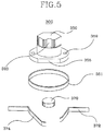
- Fig. 5 is a schematically exploded perspective view of the locking mechanism for preventing winding means from reversely rotating so that tension applied to a plurality of pulling members should not released.
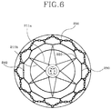
- Fig. 6 shows a snow chain disposed around an outer circumferential portion of a vehicular wheel and a mounting apparatus for the chain which is mounted to the chain.
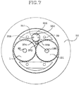
- Fig. 7 is a view for explaining the operation relationship of the locking mechanism in Fig. 5, and shows a cross-sectional view taken on line 7-7 in Fig. 2.
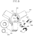
- Fig. 8 is a schematically enlarged perspective view of an alternative locking mechanism.
- Fig. 9 is a plan view of an alternative embodiment of the locking mechanism in a locking condition.
- Fig. 10 is a plan view of an alternative embodiment of the locking mechanism in a unlocking condition.
- Fig. 1 shows an anti-skid device according to the present invention, in particular an apparatus for mounting a snow chain as a plan view, in which a plurality of pulling members are completely reeled into the apparatus and are respectively connected with a plurality of hook elements at a middle portion of the pulling members. This corresponds to when the mounting apparatus is not used.
- Fig. 2 shows a cross-sectional view taken on line 2-2 in Fig. 1.
- a first and second central gearing members or a first and second central gears 1 and 101 are externally engaged with each other on a flash plane so that the clockwise rotation of the first central gear 1 simultaneously results in the counter clockwise direction of the second central gear 101.
- Beneath the first central gear 1 is disposed a first gearing member or a first gear 5 which internally engages with a first winding gearing member or a first winding gear 20.
- On the first central gear 1 is disposed a resilient member or a first spiral spring 70 opposite to the first gear 5 at a same height.
- Beneath the second central gear 101 is disposed a resilient member or a second spiral spring 170 opposite to the first gear 5 on a flash plane.
- On the second central gear 101 is disposed another gearing member or a second gear 105 which internally engages with another winding gearing member or a second winding gear 120.
- On the first central gear 1 is disposed a first spiral spring 70 opposite to the second gear 105 at a same height. Except for the winding gears 20 and 120, the first gearing members and spring 1, 5; 70 are splined with a first shaft 95 passing through their central portions, while the second gearing members and spring 101, 105; 170 are also splined with a second shaft 195 passing through their central portions.
- the first shaft 95 functions as a driving shaft, but a second shaft 195 functions as a driven shaft. Both ends of shafts 95 and 195 are supported by first and second covers 30 and 130 which are firmly clamped by bolts and nuts 200a.
- a thickness ratio of the covers 30 and 130 consists of three-fifths of the first cover 30 and two-fifths of the second cover 130, considering the entire thickness of the apparatus as one. In particular, this thickness ratio prevents the above-mentioned all gears from being pressed by clamping force applied when the apparatus for mounting the snow chain is assembled, and thereby facilitate the gears to rotate.
- the thickness may be selected at a ratio of one half of the first cover and one half of the second cover, or two-fifths of the first cover and three-fifths of the second gear.
- a plurality of pulling members have a continuous line shape comprising lower pulling members 211a whose ends 211d are secured to the first winding gear 20 and upper pulling members 211b whose ends 211c are secured to the second winding gear 120.
- the both ends of the pulling members are greater than the body in a cross-sectional dimensions.
- the first and second winding gears 20 and 120 are formed in a step shape, and the step is provided with a plurality of apertures 28 and 128 having a slit at same intervals along the steps.
- the apertures 28 and 128 are formed in such a manner that the body portion of the pulling member is allowed to come out through the slit but the end portion is not permitted to come out.
- a manual driving member 200 mounted on the top portion of the first shaft 95 begins to rotate clockwise by a tool such as a box spanner
- a plurality of members splined with the first shaft 95 i.e. the first spring 70
- the first central gear 1 and the first gear 5 are rotated in the same direction, and thus first winding gear 20 engaged with the first gear 5 and the lower pulling member 211a connected with the first winding gear 20 are rotated in the same direction.
- the central gear 101 engaged with the first central gear 1 can rotate counter clockwise together with the second shaft 195, the second spring 170, the second gear 105, the winding gear 120 and the upper pulling members 211b.
- first central gear 1 may be integrated with the first gear 5
- second central gear 101 may be integrated with the second gear 105 as well.
- an apparatus for mounting a snow chain according to the present invention may be modified into a structure in which first and second central gears 1 and 101 are eliminated.
- first and second side gearing members which are externally engaged with each other and have a geometrical shape corresponding to the first and second gears 5 and 105.
- the first side gearing member is engaged with the first gear 5, while the second side gearing member is engaged with the second gear 105.
- the side gearing member have an engaging portion substantially corresponding to the height which amounts to the engaging portion of the first gear 5 plus that of the second gear 105, i.e. twice the height of the engaging portion of the first gear 5 or 105.
- a first cover 30 includes a first recess 31 for a first gear 5, a second recess 32 for a second spiral spring 170, a recess 35 for locking member 350 of the locking mechanism 300 defined at a position isolated perpendicular to the central line linking the center of the first recess 31 with the center of the second recess 32, an aperture 40 for the end of the second spiral spring 170 having a slit along the outer periphery of the second recess 32, and through hole 39 for clamping bolt.
- the first cover 30 has a tapered surface sloped at a certain angle radially inwardly at its periphery and an arc-shaped step 45 apart from the tapered surface facing diametrically to the center line of the first and second recesses 31 and 32.
- the tapered surface is in contact with a tapered surface of the first winding gear 20 and has a function of preventing the deviation of the first winding gear 20. This is true for the second cover 130 as well.
- the recesses On the outer surface of the first cover 30, there is provided with recesses (not shown) having such a shape that a clamping bolt is sufficiently received without protrusion of its head and do not have an idle motion on clamping.
- the recesses may have a little larger size to fasten the bolt together with a rubber plate.
- Such a rubber plate will have protection against damage to a hub cover surface of a vehicular wheel, in particular in a small size vehicle, which should be in contact with the first cover 30.
- the second cover 130 includes a through hole 135 for the locking member 350, through holes 133 and 134 for supporting the one end of the first and second shafts, respectively and through hole 139 for the clamping bolt.
- the hole 135 of the second cover 130 has a diameter much smaller than that of the recess 35. As will be illustrated in reference to Fig. 8-10, around through hole 134 may be further defined at least one aperture at the same angle. Moreover the second cover 130 is also provided with recess (not shown) for a first spiral spring 70 and for a second gear 105 which has the same size and shape as the first cover 130.
- a guide member 50 disposed between the winding gears 20 and 120, which includes a plurality of guide protrusions 55 aligned at the same angular distance and extending perpendicularly up and down from its outer periphery.
- a space defined between the protrusions 55 acts as a passage way through which the pulling members are guided.
- the member 50 has an arc shaped portion 57 placed on an arc-shaped step 45 of the first cover 30. As shown in Fig. 2, this guide member 50 and the winding gears 20 and 120 couple together and define receiving portions 29 and 129 for the pulling members.
- the other end is provided with a bulging portion 66 functioning as a spring. The end contacting the pulling members presses against them so that they are reeled out of or into the receiving portions 29 and 129 without any looseness.
- first and second spline shafts 95 and 195 there are shown first and second spline shafts 95 and 195, a manual driving member 200 mounted on the top portion of the shaft 95 and first and second spiral springs 70 and 170 splined with the shafts, respectively.
- the top portion of the first shaft 95 is provided with a groove 98 fitted with snap ring 99 to prevent the manual driving member 200 from running away.
- the inner circumferential surface of the driving member is defined in the same shape as the top portion of the shaft 95 to prevent idle rotation when the driving member is driven with a tool such as box spanner.
- the top portion of the shaft 95 is partially cut out at its periphery to form a cut-out 97.
- the first spiral spring 70 has the same shape as the second spiral spring 170.
- the spring 70 has one end 71 fitted into an aperture 40 in the first cover 30 and the other end portion 75 or a central portion splined with the spline shaft 95.
- the central portion 75 is press-formed in the same shape as the spline shaft, and then bonded together with bonding means 76 such as rivet.
- bonding means 76 such as rivet.
- Such a spline shape facilitates mounting the spiral spring on the spline shaft.
- the first spring 70 is arranged to produce resilient force clockwise.
- the second spring 170 is arranged to produce resilient force counter clockwise.
- these spiral springs should be arranged so as to not produce any resilient force when the pulling members are fully received in the receiving portion 29 and 129 as shown in Fig. 2.
- the spline shaft may be selected to have a non-circular cross-sectional shape, such as pentagon, hexagon etc.
- the members splined with the spline shaft, more particularly the first and second central gears 1 and 101, the first and second gears 5 and 105 and the central portions 75 and 175 of the spiral springs may be of the cross-sectional shape corresponding to that of the shaft because this non-circular cross-sectional shape is adapted to simultaneously rotate with the shaft.
- a locking mechanism 300 for preventing the above-mentioned members from rotating in reverse is schematically shown as an exploded perspective view.
- the means 300 from top to bottom, comprises a locking member 350, an annular band spring 351, a cylindrical bearing 370 and band springs 372 and 374.
- the locking member 350 is divided into three portions, i.e. a lower portion inserted into the recess 35 of the first cover 30, a middle portion inserted through the through hole 135 of the second cover 130 and an upper portion having a shape adapted to make use of a tool such as a box spanner.
- the lower portion has a plane 355 partially cut out at its outer periphery and a concave semi-sphere 359 used to secure a locking or unlocking position by pressing on a ball bearing (not shown).
- the upper portion has a semi-cylindrical groove 320 at the same side surface as the plane 355 of the lower portion. The groove 320 is adapted to look at whether the locking member 350 takes a locking position or a unlocking position.
- the lower portion of the locking member 350 has an outer diameter similar to an inner diameter of the annular band spring 351.
- the outer diameter of the annular band spring 351 is nearly the same as the diameter of the recess 35 of the first cover 30. Therefore into the recess 35 of the first cover 30 is inserted the band spring 351 and the lower portion of the locking member in turn.
- the annular band spring 351 functions as a sliding bearing decreasing the friction produced between an outer periphery of the lower portion of the locking member and an inner periphery of the recess 35.
- Other band springs 372 and 374 for preventing the bearing 370 from deviating from its original position have one end secured to a stepped surface adjacent to the recess 35 and the other end supporting the bearing 370 by contact.
- the portion contacting the bearing 370 may be selected to have a magnetic force.
- Fig. 6 shows a snow chain and an apparatus for the chain mounted to an outer circumferential portion of a vehicular wheel, i.e. to a tire 250.
- a snow chain used in the present invention it is desirable to select a polymer chain rather than a steel chain, because the former has a better capability than the latter to withstand a heavy load.
- the snow chain in the present invention will be made use of with a continuous cable 230 which has a desired diameter and a length shorter than that of an outer periphery of tire to be mounted.
- the chain has generally a width greater than a contacting surface which a tire contacts with the roadway and a length slightly longer than that of a circumferential portion of the tire.
- the cable 230 is linked to become smaller than the diameter of the tire by means of a suitable linking means 240.
- This linking manner is also applied to the opposite side of the above-mentioned tire. As a result, the tire 250 is surrounded with the snow chain.
- a plurality of hook elements 220 is coupled to the snow chain at predetermined intervals along the side of the tire in a detachable manner but coupled to a plurality of pulling members 211a and 211b in a non-detachable manner.
- the pulling members respectively coupled to the hook elements one end is connected with a first winding gear 20 and the other end is connected with a second wind gear 120. Therefore a clockwise and a counter clockwise rotations of the winding gears cause tension to be applied to the pulling members simultaneously by drawing the pulling members or to be released from the pulling members by unwinding them. To apply and release this tension is controlled by the locking mechanism 300.
- a mounting apparatus for a snow chain avoids springing out suddenly by the both rotating direction of the pulling members.
- the tension applied to the pulling members to draw the snow chain is automatically obtained by spiral springs 70 and 170 in part, and a remaining tension is manually obtained by a spanner.
- the pulling members force the spiral springs 70 and 170 to produce a recovery force by reeling out of the receiving portions 29 and 129 of the winding gears, because the springs 70 and 170 are initially provided in a condition that it does not have any recovery force.
- the tension applied by the tool is never released as long as the locking mechanism 300 is not operated in an unlocking condition.
- pulling members 211a and 211b have a circular or rectangular cross section braided or textured by a plurality of strands of aluminum alloy, steel, reinforced fiber etc.
- the pulling members have also both ends greater than the body in a cross-sectional dimensions.
- Fig. 7 shows a cross-sectional view for explaining how the locking mechanism 300 used in an apparatus for mounting a snow chain according to the present invention effects locking and unlocking operation and is taken on the line 7-7 in Fig. 2 for its understanding.
- the first and second central gears 1 and 101 can rotate in any one of clockwise and counter clockwise direction.
- the bearing 370 firmly contacting the teeth of the second central gear 101 retreats on the plane 355 to an extent that the second central gear 101 can rotates counter clockwise.
- the retreated bearing returns back to be in contact with the teeth of the second central gear 101 by a resilient force of the annular band spring 351.
- Another band spring 374 confines the clockwise motion of the bearing 370 to a limited extent.
- the bearing 370 slightly proceeds counter clockwise but retreats slightly on the plane 355 at the same time, and thus is in contact with the teeth of the second central gear 101 by means of a resilient force of the band spring 351.
- Another band spring 372 confines the counter clockwise motion of the bearing 370 to a restricted extent.
- the bearing 370 retreats slightly on the plane 355 by the clockwise or counter clockwise rotation of the second central gear 101 but is always in contact with the teeth of the second central gear 101 by the band springs 372, 373 and 374.
- a ball bearing (not shown) contacting a semi-spherical recess 359 acts to secure both positions. This is operated in a manner similar to a ball bearing mounted on a door handle.
- the locking mechanism 300 is constructed to cooperate with the first central gear 1.
- Fig. 8 shows an alternative embodiment 400 of the locking mechanism 300 in Fig. 5.
- the locking mechanism 400 in Fig. 9 and 10 illustrates as a plan view a locking and unlocking position, respectively.
- This locking mechanism 400 is mounted to cooperate with the second shaft 195 on an outer side of the second cover 130, while the means 300 in Fig. 5 is mounted between the first cover 30 and the second cover 130. Therefore to mount the locking mechanism 400 on the outer side of the second cover 130 the second shaft 195 shown in Fig. 4 requires at least one aperture defined around the through-hole 134 through which the end of the second shaft 195 passes.
- the second shaft 195 suitable for the locking mechanism 400 should include a circular cross-sectional top portion and a groove for a snap ring 499 similar to the groove 98 for the snap ring 99 fitted into the top portion of the first shaft 95.
- bend springs 462 and 464 are respectively attached to both ends of a hinge member 460.
- a cylindrical bearing 470 is disposed between these band springs and between the shaft 195 and the hinge member 460 to contact one another.
- Another band spring 463 is attached to one end of the band spring 462 so that a locking member 450 takes up a locking position at one recess 459 and an unlocking position at the other recess 458.
- a bulging portion 451 of the locking member 450 has a similar profile to the side opposite to the side surface contacting the bearing 470 on the hinge member 460.
- the second shaft 195 can rotate in one direction, that is, counter clockwise, because the bearing 470 is disposed between the locking member 460 and the shaft 195.
- the bearing 470 is rotated in the reverse direction or clockwise by a frictional force resulting from the contact of the shaft 195, descending from a contacting surface on the locking member 460 with a rolling motion.
- the shaft 195 rotates clockwise, the bearing 470 is rotated counter clockwise by a contacting frictional force, ascending along the contacting surface on the locking member 460 with a rolling motion, and thereby after moving at a certain distance is jammed between the contacting surface of the locking member 460 and the outer periphery of the shaft 195.
- the shaft 195 may rotate in one direction only.
- a spline shaft 195 can rotate in any one of clockwise and counter clockwise direction.
- a locking member 450 moves around the shaft 195 towards the unlocking position at a certain angular distance
- above-mentioned jammed bering 470 moves further along an outer periphery of the shaft 195 with a locking force gradually decreased.
- a hinge member 460 pivots at a predetermined angle by its sliding motion with a bulging portion 451 of the locking member 450, and then the bearing 470 reaches a free position where no force is imparted.
- the bearing 470 can not deviate from the locking member 460, because it is resiliently supported between the two band springs 462 and 464. Although the bearing 470 leads to displacement due to the rotation of the shaft 195 on unlocking, it takes up its initial position again after such a displacement by the resilient force of the band spring 462.
- the bearing 470 comes into contact with the shaft 195 by means of the resilient force of the band spring 462 before the locking member 450 takes up a final locking position, and then slides and descends from the bearing-side contacting surface of the hinge member 460 until the locking member 450 occupies its final locking position.
- the locking member 450 When the locking member 450 displaces from the locking position to the unlocking position and vice versa, to maintain any one of these two positions the locking member 450 is provided with at least two longitudinal semi-circular grooves 458 and 459 which are defined on its inner periphery just adjacent to both ends of the bulging portion 451.
- the groove 458 is resiliently engaged with one end of a band spring 463.
- This band spring 463 is attached to the band spring 462 with a little resilient force applied. Owing to this resilient force, the spring 463 facilitates to disengage out of the groove 458 and to engage with another groove 459 when the locking member 450 moves between the locking position and the unlocking position.
- the locking mechanism 400 is mounted to cooperate with the first shaft 95.
- the apparatus for mounting the snow chain of the anti-skid device according to the invention to be manufactured by pressure die casting with an aluminum alloy or a reinforced plastic material in consideration of weight, environment and corrosion.
Landscapes
- Engineering & Computer Science (AREA)
- Mechanical Engineering (AREA)
- Devices For Conveying Motion By Means Of Endless Flexible Members (AREA)
Applications Claiming Priority (2)
| Application Number | Priority Date | Filing Date | Title |
|---|---|---|---|
| KR19960046117 | 1996-10-11 | ||
| KR9646117 | 1996-10-11 |
Publications (1)
| Publication Number | Publication Date |
|---|---|
| EP0835770A1 true EP0835770A1 (fr) | 1998-04-15 |
Family
ID=19477600
Family Applications (1)
| Application Number | Title | Priority Date | Filing Date |
|---|---|---|---|
| EP97402375A Withdrawn EP0835770A1 (fr) | 1996-10-11 | 1997-10-09 | Dispositif anti-dérapant pour une roue de véhicule |
Country Status (2)
| Country | Link |
|---|---|
| EP (1) | EP0835770A1 (fr) |
| KR (1) | KR19980032637A (fr) |
Cited By (6)
| Publication number | Priority date | Publication date | Assignee | Title |
|---|---|---|---|---|
| EP1621369A1 (fr) * | 2004-07-28 | 2006-02-01 | Rud-Kettenfabrik Rieger & Dietz Gmbh U. Co. | Dispositif de tension pour chaînes à neige |
| EP1787832A1 (fr) | 2005-11-18 | 2007-05-23 | Emrah Bozkurt | Dispositif tenseur pour chaînes anti-dérapantes et appareil à traction améliorée |
| EP1854646A1 (fr) * | 2006-05-12 | 2007-11-14 | Pewag Schneeketten GMBH & Co KG | Dispositif de déviation pour une chaîne antidérapante |
| EP2070735A1 (fr) | 2007-12-13 | 2009-06-17 | RuD Ketten Rieger & Dietz GmbH u. Co. KG | Dispositif de serrage pour une chaîne de pneu |
| CN109606038A (zh) * | 2018-12-30 | 2019-04-12 | 河北百龙汽车配件制造有限公司 | 一种抽拉式外胎防滑轮毂 |
| CN116252573A (zh) * | 2023-05-16 | 2023-06-13 | 之江实验室 | 一种车载防滑装置 |
Families Citing this family (1)
| Publication number | Priority date | Publication date | Assignee | Title |
|---|---|---|---|---|
| KR102122504B1 (ko) * | 2018-09-11 | 2020-06-12 | 넥센타이어 주식회사 | 타이어 장착 패치 모듈 및 타이어 장착 패치 시스템 |
Citations (5)
| Publication number | Priority date | Publication date | Assignee | Title |
|---|---|---|---|---|
| FR346636A (fr) * | 1904-09-28 | 1905-02-01 | Jean Claude Dunois | Protecteur antidérapant pour bandage de roue de véhicules automobiles, cycles, etc., motocyclettes |
| US1472448A (en) * | 1919-10-20 | 1923-10-30 | Weaver Mfg Co | Antiskid-wheel-chain construction |
| US2440632A (en) * | 1947-03-03 | 1948-04-27 | George O Hack | Traction device for resilient tires and wheels |
| FR1520579A (fr) * | 1967-02-27 | 1968-04-12 | Dispositifs antidérapants, notamment à chaînes-neige, destinés à équiper les roues d'un véhicule | |
| US5540267A (en) * | 1994-10-05 | 1996-07-30 | Rona; Thomas P. | Traction device for wheeled vehicles |
-
1997
- 1997-10-08 KR KR1019970051516A patent/KR19980032637A/ko not_active Withdrawn
- 1997-10-09 EP EP97402375A patent/EP0835770A1/fr not_active Withdrawn
Patent Citations (5)
| Publication number | Priority date | Publication date | Assignee | Title |
|---|---|---|---|---|
| FR346636A (fr) * | 1904-09-28 | 1905-02-01 | Jean Claude Dunois | Protecteur antidérapant pour bandage de roue de véhicules automobiles, cycles, etc., motocyclettes |
| US1472448A (en) * | 1919-10-20 | 1923-10-30 | Weaver Mfg Co | Antiskid-wheel-chain construction |
| US2440632A (en) * | 1947-03-03 | 1948-04-27 | George O Hack | Traction device for resilient tires and wheels |
| FR1520579A (fr) * | 1967-02-27 | 1968-04-12 | Dispositifs antidérapants, notamment à chaînes-neige, destinés à équiper les roues d'un véhicule | |
| US5540267A (en) * | 1994-10-05 | 1996-07-30 | Rona; Thomas P. | Traction device for wheeled vehicles |
Cited By (11)
| Publication number | Priority date | Publication date | Assignee | Title |
|---|---|---|---|---|
| EP1621369A1 (fr) * | 2004-07-28 | 2006-02-01 | Rud-Kettenfabrik Rieger & Dietz Gmbh U. Co. | Dispositif de tension pour chaînes à neige |
| EP1787832A1 (fr) | 2005-11-18 | 2007-05-23 | Emrah Bozkurt | Dispositif tenseur pour chaînes anti-dérapantes et appareil à traction améliorée |
| JP4879275B2 (ja) * | 2005-11-18 | 2012-02-22 | ボズクルト,エムラー | 締付システム、ならびに、タイヤ滑り止めおよび牽引力増強装置 |
| EP1854646A1 (fr) * | 2006-05-12 | 2007-11-14 | Pewag Schneeketten GMBH & Co KG | Dispositif de déviation pour une chaîne antidérapante |
| US7921521B2 (en) | 2006-05-12 | 2011-04-12 | Pewag Schneeketten Gmbh & Co. Kg | Deflection device for an anti-skid chain |
| EP2070735A1 (fr) | 2007-12-13 | 2009-06-17 | RuD Ketten Rieger & Dietz GmbH u. Co. KG | Dispositif de serrage pour une chaîne de pneu |
| DE102007060617A1 (de) | 2007-12-13 | 2009-06-18 | Rud Ketten Rieger & Dietz Gmbh U. Co. Kg | Spannvorrichtung für eine Reifenkette |
| CN109606038A (zh) * | 2018-12-30 | 2019-04-12 | 河北百龙汽车配件制造有限公司 | 一种抽拉式外胎防滑轮毂 |
| CN109606038B (zh) * | 2018-12-30 | 2022-06-14 | 河北百龙汽车配件股份有限公司 | 一种抽拉式外胎防滑轮毂 |
| CN116252573A (zh) * | 2023-05-16 | 2023-06-13 | 之江实验室 | 一种车载防滑装置 |
| CN116252573B (zh) * | 2023-05-16 | 2023-08-29 | 之江实验室 | 一种车载防滑装置 |
Also Published As
| Publication number | Publication date |
|---|---|
| KR19980032637A (ko) | 1998-07-25 |
Similar Documents
| Publication | Publication Date | Title |
|---|---|---|
| US4268012A (en) | Adjustable length strap tie down apparatus | |
| US4687253A (en) | Safety-belt system | |
| US5010970A (en) | Power-assisted steering system | |
| KR101051516B1 (ko) | 웨빙 권취 장치 | |
| DE3131637C2 (de) | Rückstrammer für Sicherheitsgurtautomaten | |
| KR101012915B1 (ko) | 웨빙 권취 장치 | |
| US6499724B1 (en) | Safety latch for a tire carrier | |
| US5415377A (en) | Sheave assembly for a tire lift/carrier winch | |
| US6419061B1 (en) | Anti-backlash mechanism | |
| CA2054144C (fr) | Appareil de levage a pneu compact | |
| US5954287A (en) | Retractor for a seat belt | |
| EP0816136A2 (fr) | Dispositif de fixation d'un module électronique | |
| US6991417B2 (en) | Spare tire handling device with a wheel retainer | |
| US4576412A (en) | Seat reclining mechanism | |
| KR100320812B1 (ko) | 자동차용 스페어 타이어 캐리어 | |
| US4254921A (en) | Winding shaft for a belt roll-up device for winding and unwinding a vehicle safety belt | |
| US6405962B1 (en) | Retractor for use with a seat belt webbing | |
| KR19980032637A (ko) | 차량의 바퀴용 미끄럼 방지장치 | |
| JP2634380B2 (ja) | ベルトリトラクター | |
| US20060169958A1 (en) | Spare tire carrier having overload protection with controlled cable payout | |
| JPH0735805Y2 (ja) | 安全ベルト巻取器 | |
| US6290047B1 (en) | Parking pawl assembly | |
| US11378185B2 (en) | Parking mechanism and method of operation thereof | |
| DE102008011790A1 (de) | Gurtaufroller für ein Sicherheitsgurtsystem | |
| US5718411A (en) | Anti-theft device for a spare tire carrier |
Legal Events
| Date | Code | Title | Description |
|---|---|---|---|
| PUAI | Public reference made under article 153(3) epc to a published international application that has entered the european phase |
Free format text: ORIGINAL CODE: 0009012 |
|
| 17P | Request for examination filed |
Effective date: 19971020 |
|
| AK | Designated contracting states |
Kind code of ref document: A1 Designated state(s): AT BE CH DE DK ES FI FR GB GR IE IT LI LU MC NL PT SE |
|
| AX | Request for extension of the european patent |
Free format text: AL;LT;LV;RO;SI |
|
| STAA | Information on the status of an ep patent application or granted ep patent |
Free format text: STATUS: THE APPLICATION HAS BEEN WITHDRAWN |
|
| 18W | Application withdrawn |
Withdrawal date: 19980912 |