EP0836018A1 - Joint à rotule et procédé de montage - Google Patents
Joint à rotule et procédé de montage Download PDFInfo
- Publication number
- EP0836018A1 EP0836018A1 EP97115854A EP97115854A EP0836018A1 EP 0836018 A1 EP0836018 A1 EP 0836018A1 EP 97115854 A EP97115854 A EP 97115854A EP 97115854 A EP97115854 A EP 97115854A EP 0836018 A1 EP0836018 A1 EP 0836018A1
- Authority
- EP
- European Patent Office
- Prior art keywords
- cover
- ball
- housing
- bearing surface
- joint
- Prior art date
- Legal status (The legal status is an assumption and is not a legal conclusion. Google has not performed a legal analysis and makes no representation as to the accuracy of the status listed.)
- Granted
Links
- 238000000034 method Methods 0.000 title description 2
- 238000003825 pressing Methods 0.000 claims description 3
- 229920003023 plastic Polymers 0.000 description 7
- 239000004033 plastic Substances 0.000 description 7
- 238000004519 manufacturing process Methods 0.000 description 6
- 238000013461 design Methods 0.000 description 5
- 239000000463 material Substances 0.000 description 4
- 238000003860 storage Methods 0.000 description 4
- 230000009471 action Effects 0.000 description 3
- 239000000919 ceramic Substances 0.000 description 3
- XEEYBQQBJWHFJM-UHFFFAOYSA-N Iron Chemical compound [Fe] XEEYBQQBJWHFJM-UHFFFAOYSA-N 0.000 description 2
- 238000013459 approach Methods 0.000 description 2
- 238000005461 lubrication Methods 0.000 description 2
- 238000012549 training Methods 0.000 description 2
- 229910000760 Hardened steel Inorganic materials 0.000 description 1
- 229910000831 Steel Inorganic materials 0.000 description 1
- 230000008859 change Effects 0.000 description 1
- 239000002131 composite material Substances 0.000 description 1
- 238000005553 drilling Methods 0.000 description 1
- 230000008030 elimination Effects 0.000 description 1
- 238000003379 elimination reaction Methods 0.000 description 1
- 238000003780 insertion Methods 0.000 description 1
- 230000037431 insertion Effects 0.000 description 1
- 229910052742 iron Inorganic materials 0.000 description 1
- 239000002184 metal Substances 0.000 description 1
- 229910052751 metal Inorganic materials 0.000 description 1
- 230000008569 process Effects 0.000 description 1
- 230000002787 reinforcement Effects 0.000 description 1
- 239000012858 resilient material Substances 0.000 description 1
- 239000010959 steel Substances 0.000 description 1
- 238000012360 testing method Methods 0.000 description 1
- 230000007704 transition Effects 0.000 description 1
Images

Classifications
-
- F—MECHANICAL ENGINEERING; LIGHTING; HEATING; WEAPONS; BLASTING
- F16—ENGINEERING ELEMENTS AND UNITS; GENERAL MEASURES FOR PRODUCING AND MAINTAINING EFFECTIVE FUNCTIONING OF MACHINES OR INSTALLATIONS; THERMAL INSULATION IN GENERAL
- F16C—SHAFTS; FLEXIBLE SHAFTS; ELEMENTS OR CRANKSHAFT MECHANISMS; ROTARY BODIES OTHER THAN GEARING ELEMENTS; BEARINGS
- F16C11/00—Pivots; Pivotal connections
- F16C11/04—Pivotal connections
- F16C11/06—Ball-joints; Other joints having more than one degree of angular freedom, i.e. universal joints
- F16C11/0619—Ball-joints; Other joints having more than one degree of angular freedom, i.e. universal joints the female part comprising a blind socket receiving the male part
- F16C11/0623—Construction or details of the socket member
- F16C11/0642—Special features of the plug or cover on the blind end of the socket
-
- Y—GENERAL TAGGING OF NEW TECHNOLOGICAL DEVELOPMENTS; GENERAL TAGGING OF CROSS-SECTIONAL TECHNOLOGIES SPANNING OVER SEVERAL SECTIONS OF THE IPC; TECHNICAL SUBJECTS COVERED BY FORMER USPC CROSS-REFERENCE ART COLLECTIONS [XRACs] AND DIGESTS
- Y10—TECHNICAL SUBJECTS COVERED BY FORMER USPC
- Y10T—TECHNICAL SUBJECTS COVERED BY FORMER US CLASSIFICATION
- Y10T29/00—Metal working
- Y10T29/49—Method of mechanical manufacture
- Y10T29/49636—Process for making bearing or component thereof
- Y10T29/49643—Rotary bearing
- Y10T29/49647—Plain bearing
- Y10T29/49648—Self-adjusting or self-aligning, including ball and socket type, bearing and component making
- Y10T29/49657—Socket making
- Y10T29/49663—Socket making by assembling
-
- Y—GENERAL TAGGING OF NEW TECHNOLOGICAL DEVELOPMENTS; GENERAL TAGGING OF CROSS-SECTIONAL TECHNOLOGIES SPANNING OVER SEVERAL SECTIONS OF THE IPC; TECHNICAL SUBJECTS COVERED BY FORMER USPC CROSS-REFERENCE ART COLLECTIONS [XRACs] AND DIGESTS
- Y10—TECHNICAL SUBJECTS COVERED BY FORMER USPC
- Y10T—TECHNICAL SUBJECTS COVERED BY FORMER US CLASSIFICATION
- Y10T29/00—Metal working
- Y10T29/49—Method of mechanical manufacture
- Y10T29/49826—Assembling or joining
- Y10T29/4984—Retaining clearance for motion between assembled parts
- Y10T29/49845—Retaining clearance for motion between assembled parts by deforming interlock
- Y10T29/49853—Retaining clearance for motion between assembled parts by deforming interlock of sphere, i.e., ball, in socket
-
- Y—GENERAL TAGGING OF NEW TECHNOLOGICAL DEVELOPMENTS; GENERAL TAGGING OF CROSS-SECTIONAL TECHNOLOGIES SPANNING OVER SEVERAL SECTIONS OF THE IPC; TECHNICAL SUBJECTS COVERED BY FORMER USPC CROSS-REFERENCE ART COLLECTIONS [XRACs] AND DIGESTS
- Y10—TECHNICAL SUBJECTS COVERED BY FORMER USPC
- Y10T—TECHNICAL SUBJECTS COVERED BY FORMER US CLASSIFICATION
- Y10T403/00—Joints and connections
- Y10T403/32—Articulated members
- Y10T403/32606—Pivoted
- Y10T403/32631—Universal ball and socket
- Y10T403/32737—Universal ball and socket including liner, shim, or discrete seat
- Y10T403/32762—Spring-biased seat opposite ball stud
-
- Y—GENERAL TAGGING OF NEW TECHNOLOGICAL DEVELOPMENTS; GENERAL TAGGING OF CROSS-SECTIONAL TECHNOLOGIES SPANNING OVER SEVERAL SECTIONS OF THE IPC; TECHNICAL SUBJECTS COVERED BY FORMER USPC CROSS-REFERENCE ART COLLECTIONS [XRACs] AND DIGESTS
- Y10—TECHNICAL SUBJECTS COVERED BY FORMER USPC
- Y10T—TECHNICAL SUBJECTS COVERED BY FORMER US CLASSIFICATION
- Y10T403/00—Joints and connections
- Y10T403/32—Articulated members
- Y10T403/32606—Pivoted
- Y10T403/32631—Universal ball and socket
- Y10T403/32811—Spring-biased
Definitions
- the invention relates to a ball joint, in particular as a leading joint for Motor vehicles, with a spherical ring-shaped bearing surface Articulated housing in which a ball arranged on a ball pin limited rotatable and tiltable and that by a lid is closed, which in the initial state with an inner diameter a smooth-walled cylindrical bore of the joint housing Exceeding outer diameter is formed and the Installed state with its edge supported non-positively in the joint housing. Furthermore, the invention relates to a device for mounting such Ball joint.
- Such a ball joint is known from DE patent 195 13 826.
- this known ball joint Avoiding a fixed contact surface for the cover manufacturing tolerances completely compensate.
- a spring element is arranged, the spring forces defined in the initial state provides the wear-related elasticity of the joint balance.
- This joint has proven itself in dynamic tests well proven, but based on calculations it was found that on the one hand the life of the spring elements is less than that Lifetime of the ball joint and on the other hand the constant load on the Ball in the direction of the longitudinal axis of the ball pin through the spring element inevitable to increased wear of the bearing surface in the axial Direction leads. Add to that that due to the constant Unfavorable pressure load of the ball in the direction of the bearing surface Lubrication conditions of the one which is usually provided with permanent lubrication Ball joint can occur.
- the invention has for its object to provide a ball joint that can be inexpensively automated and is reliable over a long period of time with little wear. Furthermore, the invention has for its object to provide a simple device for mounting such a ball joint.
- the solution to this problem by the invention is characterized in that the cover is in turn formed on the side of the ball equator opposite the spherical bearing surface of the joint housing with a spherical bearing surface for the ball.
- the not by positive locking that is, by accepting Manufacturing tolerances, but non-positively, that is, assembled without play, can have a spring between the cover and a separate upper bearing shell omitted. Since none in the inventive design of the ball joint axially acting spring is used, there is not only one Cheaper by the elimination of an expensive element, but it is also eliminated the wear caused by the spring required to compensate for play axial direction.
- the joint according to the invention which in particular as leading joint used and therefore mainly in the radial direction is loaded, there is a crescent-shaped wear on the circular bearing surfaces only in the radial to the longitudinal axis of the ball stud direction, d. H. there is also no wear relevant play in the axial direction.
- the spherical ring-shaped bearing surface of the cover is either immediate or indirectly on the surface of the sphere, d. H. without intermediate spring made of resilient or resilient material.
- the bearing surface is Storage of the ball arranged on the ball pin in one piece as part of the Articulated housing trained.
- the Housing is hardened in the area of the spherical bearing surface the entire assembly, which forms the ball joint, from only three components, namely the joint housing, the ball pin with an arranged ball and the cover for closing the joint housing. Due to the Limiting the number of components to the minimum is one of them assembled ball joint extremely easy and inexpensive to manufacture.
- the bearing surface is arranged on a separate part in the housing Bearing shell formed.
- This embodiment allows for simple Way an adjustment of the bearing surface of the ball joint to different Operating conditions.
- suitable choice of the material of the bearing shell for example hardened metal, plastic or ceramic is one Adjustment of the ball joint possible in a simple way.
- a centering of the ball in the radial direction when the radial occurred Wear can occur according to a further embodiment of the invention are caused by the fact that on the outer edge of a between cover and Spherical surface arranged intermediate element formed centering approaches are supported on the cover and / or joint housing. Through the play-free arrangement of these intermediate elements on the inside of the housing Cover, the intermediate elements have no spring action in the axial direction exercise as is known in the art.
- the joint housing with a chamfer surrounding cylindrical bore.
- the invention proposes that the edge of the housing after completing the assembly of the cover for the positive determination of the Lid is formed. This form-fitting fixing of the lid takes place without changing the previous position of the cover and thus in no way affects the axial loading of the ball by the Cover.
- the device for mounting a ball joint is characterized by a pushing the cover into the joint housing Assembly mandrel, which on its end face with an annular, on the lid adjacent pressure surface is formed.
- this circular pressure surface is caused not in the center, but in Distance from the center of the lid is pressed onto the lid, so that the Cover only with the later spherical bearing surface on the ball is present.
- the invention proposes a on the mounting mandrel To arrange the cover guide ring.
- the use of such The cover guide ring has proven to be advantageous because it tilts it of the lid can be prevented during assembly. Since the impression of the The cover in the joint housing only takes place via the assembly mandrel
- the lid guide ring normally has a slight clearance to the edge of the lid.
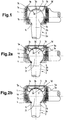
- the fully assembled ball joint shown in Fig. 1 includes a Articulated housing 1, which with a cylindrical bore 1a and ball-shaped bearing surface 1b is provided. At which the spherical ring-shaped bearing surface 1b adjoining the lower end Joint housing 1 has a passage opening 1c for a ball pin 2.
- the ball pin 2 includes a slightly conical in the embodiment Pin part 2a, which by means of an opposite conical transition 2b in a Bearing ball 2c merges.
- This bearing ball 2c is below its largest Diameter on the spherical ring-shaped bearing surface 1b of the joint housing 1 on.
- the bearing surface 1b is in one piece formed as part of the joint housing 1. In such an embodiment the bearing surface 1b is hardened, for example case hardened.
- This configuration of the cover 3 ensures that the cover 3 can be pressed into the joint housing 1 with a relatively low assembly force F 1 , which acts on the cover 3 not centrally but at a distance from the center of the cover, as shown by the lines of action in FIG 3 can be seen. Due to the design of the cover 3 and in particular the oblique edge region 3c, the edge region 3c bends elastically back against the pushing-in movement during assembly, so that the outer diameter of the cover 3, which is larger in the initial state, can be easily adapted to the smaller inner diameter, that is to say the bore 1 a of the joint housing 1 results.
- the pushing-in movement of the cover 3 is ended as soon as contact with the surface of the ball 2c has been reached and a predetermined pushing-in force F 1 has been reached.
- the cover 3 pressed into the joint housing 1 in this way now rests with its spherical bearing surface 3a against the ball 2c without play. In this way, all manufacturing tolerances can be compensated for when the cover assembly is completed.
- the deformed edge regions 3c of the cover 3 in the assembled state bring about a secure fixing of the cover edge on the joint housing 1, since the restoring forces present in this edge region tend to push the center region 3b of the cover 3 back out of the cylindrical bore 1a of the joint housing 1, the diameter increase required for this of the cover 3, however, is prevented by the contact of its edge region 3c in the cylindrical bore 1a of the joint housing 1. This results in a clamping force which holds the cover 3 securely in the cylindrical bore 1 a of the joint housing 1, despite the exclusively non-positive fixing.
- Fig. 1 represents a ball joint that only three components, namely the joint housing 1, the ball stud 2 with arranged ball 2 c and the lid 3 there.
- the spherical ring-shaped bearing surface 1b of the joint housing 1 not in one piece as part of the joint housing 1 formed, but on a separate part in the joint housing 1 arranged bearing shell 4 formed.
- the bearing shell 4 has a radial outwardly projecting edge 4a and ends in front of the passage opening 1c in the lower part of the joint housing 1.
- the as a separate part in the Articulated housing 1 insertable cups 4 can be made from any suitable Material, such as hardened steel, plastic or ceramic.
- FIG. 2a shows another difference arranged between cover 3 and surface of the ball 2c wear-preventing intermediate element 5.
- This intermediate element 5 after assembly is free of play between cover 3 and ball 2c.
- the intermediate elements 5 can act as a wear-preventing element centering the ball 2c in the radial direction when the radial occurred Wear caused by the fact that at the outer edge of the intermediate element 5 Centering lugs 5a are formed.
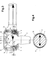
- Fig. 3 are the fourth embodiment of a ball joint various lines of force lines, for example, which at Assembly and occur when operating a ball joint.
- the fourth Embodiment corresponds essentially to that shown in Fig. 1 Embodiment, however, the bearing surface for the ball 2 is on as separate part in the joint housing 1 arranged bearing shell 4 is formed.
- FIG. 4 which represents a cross section through the ball 2c and the bearing shell 4 according to FIG. 3, the radial forces F R of such a ball joint, which is predominantly loaded in the radial direction, lead to crescent-shaped wear on the annular bearing surfaces 1b only in the radial direction to the direction of the longitudinal axis of the ball pin, that is to say that there is no play of the joint in the axial direction even when wear occurs.
- 5a to 5d is an example of the assembly of a ball joint and especially the lid assembly shown.
- To mount the cover 3 one consisting of a mounting mandrel 7a and a cover guide ring 7b Tool 7 used.
- the Cover 3 placed on the edge 1d of the joint housing 1 and that Tool 7 attached to the cover 3.
- the edge 1d With a chamfer 1e surrounding the cylindrical bore 1a.
- On the mounting mandrel 7a is also attached to its end face engaging on the cover 3 an annular pressure surface, which causes that not centrally, but in a ring at a distance from the center of the lid onto the lid 3 is pressed.
Landscapes
- Engineering & Computer Science (AREA)
- General Engineering & Computer Science (AREA)
- Mechanical Engineering (AREA)
- Pivots And Pivotal Connections (AREA)
- Joints Allowing Movement (AREA)
Applications Claiming Priority (2)
| Application Number | Priority Date | Filing Date | Title |
|---|---|---|---|
| DE19638466A DE19638466C1 (de) | 1996-09-19 | 1996-09-19 | Kugelgelenke sowie Vorrichtung zur Montage eines Kugelgelenkes |
| DE19638466 | 1996-09-19 |
Publications (2)
| Publication Number | Publication Date |
|---|---|
| EP0836018A1 true EP0836018A1 (fr) | 1998-04-15 |
| EP0836018B1 EP0836018B1 (fr) | 2003-03-12 |
Family
ID=7806267
Family Applications (1)
| Application Number | Title | Priority Date | Filing Date |
|---|---|---|---|
| EP97115854A Expired - Lifetime EP0836018B1 (fr) | 1996-09-19 | 1997-09-12 | Joint à rotule et procédé de montage |
Country Status (6)
| Country | Link |
|---|---|
| US (1) | US6030141A (fr) |
| EP (1) | EP0836018B1 (fr) |
| JP (1) | JP2000500851A (fr) |
| DE (2) | DE19638466C1 (fr) |
| ES (1) | ES2195062T3 (fr) |
| WO (1) | WO1998012439A1 (fr) |
Cited By (1)
| Publication number | Priority date | Publication date | Assignee | Title |
|---|---|---|---|---|
| WO2007115515A1 (fr) * | 2006-03-20 | 2007-10-18 | Zf Friedrichshafen Ag | Agencement d'articulation et/ou de palier |
Families Citing this family (21)
| Publication number | Priority date | Publication date | Assignee | Title |
|---|---|---|---|---|
| US6382865B1 (en) * | 1999-06-21 | 2002-05-07 | Richard C. Paxman | Base-mounted lubricated ball joint |
| DE10130758B4 (de) * | 2001-06-19 | 2005-11-03 | Alfred Heyd Gmbh U. Co. | Kugelgelenk |
| US6619873B2 (en) * | 2001-09-06 | 2003-09-16 | Federal-Mogul World Wide, Inc. | Device and method for closing movable socket assemblies by expanding solid cover plates |
| US20030086756A1 (en) * | 2001-11-07 | 2003-05-08 | Trotter Jason K | Modular linkage system |
| US6875388B2 (en) | 2001-11-07 | 2005-04-05 | Illinois Tool Works Inc. | Method for making a ball and socket joint |
| US6929271B2 (en) | 2001-11-09 | 2005-08-16 | Illinois Tool Works Inc. | Hydraulically compensated stabilizer system |
| DE10314902C5 (de) * | 2003-04-01 | 2010-09-23 | ZF Lemförder GmbH | Kugelgelenk mit Dichtungsbalg |
| TWM256036U (en) * | 2004-03-22 | 2005-01-21 | Global Target Entpr Inc | Adjustable bluetooth wireless earphone |
| DE202004012604U1 (de) * | 2004-08-11 | 2004-12-23 | Trw Automotive Gmbh | Kugelgelenk |
| DE102005028515A1 (de) * | 2005-06-17 | 2006-12-28 | Zf Friedrichshafen Ag | Kugelgelenk |
| KR100816381B1 (ko) * | 2006-12-22 | 2008-03-25 | 주식회사 만도 | 처짐방지기능이 구비된 타이로드와 볼시트를 포함하는자동차 조향장치 |
| KR100834211B1 (ko) * | 2007-02-05 | 2008-05-30 | 위아 주식회사 | 볼 조인트의 볼 스터드 고정 장치 |
| JP5970187B2 (ja) * | 2008-11-12 | 2016-08-17 | ボーグワーナー インコーポレーテッド | ターボチャージャの連結ロッド |
| USD628143S1 (en) * | 2009-10-02 | 2010-11-30 | Tomtom International B.V. | Non-integrated mounting device for use in a vehicle |
| KR20110063164A (ko) * | 2009-12-04 | 2011-06-10 | 현대자동차주식회사 | 서스펜션 암 |
| DE102011118852A1 (de) * | 2011-11-18 | 2013-05-23 | Benteler Automobiltechnik Gmbh | Kugelgelenk |
| FR3016940B1 (fr) * | 2014-01-29 | 2016-12-02 | Jtekt Europe Sas | Utilisation d’une coupelle d’obturation de rotule comme organe de rattrapage de jeu |
| DE102016206863A1 (de) * | 2016-04-22 | 2017-10-26 | Zf Friedrichshafen Ag | Axialkugelgelenk und längeneinstellbarer Zweipunktlenker mit einem solchen Axialkugelgelenk |
| DE102016206864A1 (de) * | 2016-04-22 | 2017-10-26 | Zf Friedrichshafen Ag | Kugelgelenk, insbesondere für ein Fahrwerk eines Kraftfahrzeugs, sowie Verfahren zur Montage eines solchen Kugelgelenks |
| EP3669092B1 (fr) | 2017-08-16 | 2022-06-22 | Multimatic, Inc. | Joint à rotule avec palier moulé par injection |
| US11708852B2 (en) * | 2021-06-27 | 2023-07-25 | Federal-Mogul Motorspots Llc | Ball joint, method of manufacturing a ball joint, and tool for manufacturing a ball joint |
Citations (6)
| Publication number | Priority date | Publication date | Assignee | Title |
|---|---|---|---|---|
| FR1171068A (fr) * | 1957-02-15 | 1959-01-22 | Ehrenreich & Cie A | Articulation à rotule, notamment pour timoneries de direction des véhicules automobiles |
| GB917866A (en) * | 1958-11-25 | 1963-02-06 | Automotive Prod Co Ltd | Improvements in or relating to ball-and-socket joints |
| FR2075134A5 (fr) * | 1970-01-20 | 1971-10-08 | Trw Inc | |
| US4163617A (en) | 1977-02-14 | 1979-08-07 | Musashisemitsukoguo Kabushikikaisha | Ball joint |
| FR2503291A1 (fr) * | 1981-04-06 | 1982-10-08 | Gulf & Western Mfg Co | Joint a rotule |
| DE19513826C1 (de) | 1995-04-12 | 1996-07-04 | Trw Fahrwerksyst Gmbh & Co | Kugelgelenk |
Family Cites Families (7)
| Publication number | Priority date | Publication date | Assignee | Title |
|---|---|---|---|---|
| US3571880A (en) * | 1969-04-07 | 1971-03-23 | Columbus Auto Parts Co The | Method of assembling pivot joints |
| US3656221A (en) * | 1970-02-02 | 1972-04-18 | Moog Industries Inc | Method of assembly of joint devices and apparatus therefor |
| JPS4910780B1 (fr) * | 1970-10-13 | 1974-03-13 | ||
| DE2210351A1 (de) * | 1971-03-05 | 1972-09-21 | Ishikawa Tekko Kk | Kugelgelenk |
| US4283833A (en) * | 1979-03-16 | 1981-08-18 | The Bendix Corporation | Method of attaching a ball joint to a suspension member |
| DE3315718C2 (de) * | 1983-04-29 | 1986-06-26 | Lemförder Metallwaren AG, 2844 Lemförde | Kugelgelenk für insbesondere hochbelastete Gelenkgestänge in Kraftfahrzeugen |
| DE9304897U1 (de) * | 1993-03-31 | 1993-06-03 | P.C. Turck GmbH & Co. KG, 58507 Lüdenscheid | Kugelgelenk |
-
1996
- 1996-09-19 DE DE19638466A patent/DE19638466C1/de not_active Expired - Fee Related
-
1997
- 1997-09-12 EP EP97115854A patent/EP0836018B1/fr not_active Expired - Lifetime
- 1997-09-12 DE DE59709475T patent/DE59709475D1/de not_active Expired - Fee Related
- 1997-09-12 ES ES97115854T patent/ES2195062T3/es not_active Expired - Lifetime
- 1997-09-16 WO PCT/EP1997/005059 patent/WO1998012439A1/fr not_active Ceased
- 1997-09-16 JP JP10514279A patent/JP2000500851A/ja not_active Ceased
- 1997-09-16 US US09/068,711 patent/US6030141A/en not_active Expired - Fee Related
Patent Citations (6)
| Publication number | Priority date | Publication date | Assignee | Title |
|---|---|---|---|---|
| FR1171068A (fr) * | 1957-02-15 | 1959-01-22 | Ehrenreich & Cie A | Articulation à rotule, notamment pour timoneries de direction des véhicules automobiles |
| GB917866A (en) * | 1958-11-25 | 1963-02-06 | Automotive Prod Co Ltd | Improvements in or relating to ball-and-socket joints |
| FR2075134A5 (fr) * | 1970-01-20 | 1971-10-08 | Trw Inc | |
| US4163617A (en) | 1977-02-14 | 1979-08-07 | Musashisemitsukoguo Kabushikikaisha | Ball joint |
| FR2503291A1 (fr) * | 1981-04-06 | 1982-10-08 | Gulf & Western Mfg Co | Joint a rotule |
| DE19513826C1 (de) | 1995-04-12 | 1996-07-04 | Trw Fahrwerksyst Gmbh & Co | Kugelgelenk |
Cited By (1)
| Publication number | Priority date | Publication date | Assignee | Title |
|---|---|---|---|---|
| WO2007115515A1 (fr) * | 2006-03-20 | 2007-10-18 | Zf Friedrichshafen Ag | Agencement d'articulation et/ou de palier |
Also Published As
| Publication number | Publication date |
|---|---|
| US6030141A (en) | 2000-02-29 |
| EP0836018B1 (fr) | 2003-03-12 |
| ES2195062T3 (es) | 2003-12-01 |
| JP2000500851A (ja) | 2000-01-25 |
| DE19638466C1 (de) | 1998-03-26 |
| DE59709475D1 (de) | 2003-04-17 |
| WO1998012439A1 (fr) | 1998-03-26 |
Similar Documents
| Publication | Publication Date | Title |
|---|---|---|
| EP0836018B1 (fr) | Joint à rotule et procédé de montage | |
| EP0766029B1 (fr) | Electrovanne et procédé de fabrication | |
| DE10060638B4 (de) | Radlagereinheit | |
| DE4209835B4 (de) | Kugelverbindung | |
| DE3821786C2 (fr) | ||
| EP0737820B1 (fr) | Articulation à rotule | |
| EP0513562A1 (fr) | Dispositif de transport | |
| DE2451084A1 (de) | Kugelgelenk | |
| DE112019003571T5 (de) | Kugelpfannenbaugruppe mit gepresster abdeckplatte und verfahren zu ihrer herstellung | |
| EP0924441A1 (fr) | Articulation à rotule et procédé pour la précontraindre | |
| EP1778988B1 (fr) | Joint spherique | |
| DE4108827C2 (fr) | ||
| EP0559652B1 (fr) | Arret a bille pour le maintien d'un element de commande en position, notamment de la timonerie de changement de vitesse de vehicules a moteur | |
| DE102008042281A1 (de) | Wellenlagerung in einem Lenksystem und damit ausgestattetes Lenkgetriebe sowie Verfahren zur Herstellung einer Halterung dafür | |
| EP1474615B2 (fr) | Articulation elastomere | |
| EP1744082B1 (fr) | Actionneur, notamment pour un véhicule automobile | |
| DE4204630C2 (de) | Kugelraste für die Lagefixierung eines beweglichen Stellelementes | |
| DE69931693T2 (de) | Halter für ein Gleichlaufgelenk | |
| DE102004058963A1 (de) | Zahnriemenscheibe | |
| EP0732645A1 (fr) | Boulon d'arrêt | |
| DE102019116034B4 (de) | Kugelgelenk und Verfahren zu dessen Herstellung | |
| DE112019003614T5 (de) | Faserverstärktes lager für eine kugelpfannenbaugruppe, kugelpfannenbaugruppe damit und verfahren zu deren herstellung | |
| EP1163457A1 (fr) | Palier a roulement pour les mouvements longitudinaux d'une tige de commande des fourchettes | |
| EP1681478B1 (fr) | Articulation à rotule | |
| DE3109787A1 (de) | Abgedichtetes waelzlager |
Legal Events
| Date | Code | Title | Description |
|---|---|---|---|
| PUAI | Public reference made under article 153(3) epc to a published international application that has entered the european phase |
Free format text: ORIGINAL CODE: 0009012 |
|
| AK | Designated contracting states |
Kind code of ref document: A1 Designated state(s): DE ES FR GB IT |
|
| RAX | Requested extension states of the european patent have changed |
Free format text: AL;LT;LV;RO;SI |
|
| 17P | Request for examination filed |
Effective date: 19981015 |
|
| AKX | Designation fees paid |
Free format text: DE ES FR GB IT |
|
| RBV | Designated contracting states (corrected) |
Designated state(s): DE ES FR GB IT |
|
| 17Q | First examination report despatched |
Effective date: 20010605 |
|
| GRAH | Despatch of communication of intention to grant a patent |
Free format text: ORIGINAL CODE: EPIDOS IGRA |
|
| GRAH | Despatch of communication of intention to grant a patent |
Free format text: ORIGINAL CODE: EPIDOS IGRA |
|
| GRAA | (expected) grant |
Free format text: ORIGINAL CODE: 0009210 |
|
| AK | Designated contracting states |
Designated state(s): DE ES FR GB IT |
|
| REG | Reference to a national code |
Ref country code: GB Ref legal event code: FG4D Free format text: NOT ENGLISH |
|
| REF | Corresponds to: |
Ref document number: 59709475 Country of ref document: DE Date of ref document: 20030417 Kind code of ref document: P |
|
| GBT | Gb: translation of ep patent filed (gb section 77(6)(a)/1977) |
Effective date: 20030515 |
|
| ET | Fr: translation filed | ||
| PLBE | No opposition filed within time limit |
Free format text: ORIGINAL CODE: 0009261 |
|
| STAA | Information on the status of an ep patent application or granted ep patent |
Free format text: STATUS: NO OPPOSITION FILED WITHIN TIME LIMIT |
|
| 26N | No opposition filed |
Effective date: 20031215 |
|
| PGFP | Annual fee paid to national office [announced via postgrant information from national office to epo] |
Ref country code: GB Payment date: 20050809 Year of fee payment: 9 |
|
| PGFP | Annual fee paid to national office [announced via postgrant information from national office to epo] |
Ref country code: FR Payment date: 20050902 Year of fee payment: 9 |
|
| PGFP | Annual fee paid to national office [announced via postgrant information from national office to epo] |
Ref country code: ES Payment date: 20050916 Year of fee payment: 9 |
|
| PGFP | Annual fee paid to national office [announced via postgrant information from national office to epo] |
Ref country code: DE Payment date: 20060929 Year of fee payment: 10 |
|
| PGFP | Annual fee paid to national office [announced via postgrant information from national office to epo] |
Ref country code: IT Payment date: 20060930 Year of fee payment: 10 |
|
| GBPC | Gb: european patent ceased through non-payment of renewal fee |
Effective date: 20060912 |
|
| REG | Reference to a national code |
Ref country code: FR Ref legal event code: ST Effective date: 20070531 |
|
| PG25 | Lapsed in a contracting state [announced via postgrant information from national office to epo] |
Ref country code: GB Free format text: LAPSE BECAUSE OF NON-PAYMENT OF DUE FEES Effective date: 20060912 |
|
| REG | Reference to a national code |
Ref country code: ES Ref legal event code: FD2A Effective date: 20060913 |
|
| PG25 | Lapsed in a contracting state [announced via postgrant information from national office to epo] |
Ref country code: ES Free format text: LAPSE BECAUSE OF NON-PAYMENT OF DUE FEES Effective date: 20060913 |
|
| PG25 | Lapsed in a contracting state [announced via postgrant information from national office to epo] |
Ref country code: FR Free format text: LAPSE BECAUSE OF NON-PAYMENT OF DUE FEES Effective date: 20061002 |
|
| PG25 | Lapsed in a contracting state [announced via postgrant information from national office to epo] |
Ref country code: DE Free format text: LAPSE BECAUSE OF NON-PAYMENT OF DUE FEES Effective date: 20080401 |
|
| PG25 | Lapsed in a contracting state [announced via postgrant information from national office to epo] |
Ref country code: IT Free format text: LAPSE BECAUSE OF NON-PAYMENT OF DUE FEES Effective date: 20070912 |