EP0836125A2 - Pièce d'horlogerie électronique avec dispositif de réveil - Google Patents
Pièce d'horlogerie électronique avec dispositif de réveil Download PDFInfo
- Publication number
- EP0836125A2 EP0836125A2 EP97307250A EP97307250A EP0836125A2 EP 0836125 A2 EP0836125 A2 EP 0836125A2 EP 97307250 A EP97307250 A EP 97307250A EP 97307250 A EP97307250 A EP 97307250A EP 0836125 A2 EP0836125 A2 EP 0836125A2
- Authority
- EP
- European Patent Office
- Prior art keywords
- alarm
- electronic timepiece
- lever
- hand
- indicator
- Prior art date
- Legal status (The legal status is an assumption and is not a legal conclusion. Google has not performed a legal analysis and makes no representation as to the accuracy of the status listed.)
- Withdrawn
Links
- 230000000007 visual effect Effects 0.000 claims description 7
- 238000004804 winding Methods 0.000 claims description 2
- 238000012986 modification Methods 0.000 description 1
- 230000004048 modification Effects 0.000 description 1
Images


Classifications
-
- G—PHYSICS
- G04—HOROLOGY
- G04B—MECHANICALLY-DRIVEN CLOCKS OR WATCHES; MECHANICAL PARTS OF CLOCKS OR WATCHES IN GENERAL; TIME PIECES USING THE POSITION OF THE SUN, MOON OR STARS
- G04B23/00—Arrangements producing acoustic signals at preselected times
- G04B23/02—Alarm clocks
- G04B23/021—Controls (winding up the alarm; adjusting and indicating the waking time)
Definitions
- the present invention relates to an alarm electronic timepiece having a function switching indication means provided with an alarm mechanism.
- an alarm switching mechanism is operated by the operation of an external operate stem 14, by which an alarm switch lever 15 is moved.
- the alarm switch lever 15 has a colour indicator 15a formed by printing so as to discriminate the switching indication.
- a printed portion 15a of the alarm switch lever 15 is indicated through a window 16a of a dial 16 for a visual check of the function switching.
- the dial requires the window for indication, and the alarm switch lever requires a colour print or character print formed thereon.
- the indication under the dial and the rotation angle of the alarm switch lever are limited, so that the window shape cannot be increased, resulting in a difficulty in looking at the switching indication.
- the design is limited, so that design development is difficult.
- this invention provides an alarm electronic timepiece in which an alarm function switching indication means is provided in an alarm switching mechanism, by which alarm switching indication is given on the upper face of a dial by an alarm setting indicator hand.
- this invention provides an alarm electronic timepiece comprising an alarm switching mechanism including manually operable means, and indicator means coupled to said manually operable means for providing a visual indication of the status of the alarm, characterised in that the indicator means comprises a visual indication formed on the visible face of a dial and hand or flap means coupled for movement to the manually operable means, for selectively covering or displaying the visual indication.
- the axial switching operation of the external operable stem is converted into rotation of the alarm switch lever and an alarm indicator axle.
- a hand is attached to the tip end of the alarm indicator axle, and a switching indication portion is provided on the upper face of the dial.
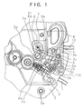
- FIG. 1 is a plan view of a switching indication structure for an alarm electronic timepiece in accordance with the present invention.
- FIG. 2 is a sectional view of a switching indication structure for an alarm electronic timepiece in accordance with the present invention.
- FIG. 3 is a sectional view of a switching indication structure for an alarm electronic timepiece in accordance with the present invention.
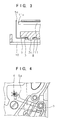
- FIG. 4 is a plan view of another embodiment of a structure in which an alarm indicator axle is rotated.
- FIG. 5 is a sectional view of another embodiment of a structure in which an alarm indicator axle is rotated.
- FIG. 6 is a plan view of a conventional switching indication structure.
- a correction mechanism which can correct the alarm setting time by using the external operate stem, is provided with a function switching indication means.
- the function switching indication means gives the indication printed on the upper face of the dial by using an alarm setting indicator hand.
- An axle to which the alarm setting indicator hand is attached is rotated by the operation of the external operate stem.
- the axial operation of the external operate stem is converted into the rotation of the alarm indicator axle by a lever member, for example.
- FIG. 1 is a plan view of a switching indication structure for an alarm electronic timepiece of one embodiment in accordance with the present invention.
- FIGS. 2 and 3 are sectional views of a switching indication structure for an alarm electronic timepiece of one embodiment in accordance with the present invention.
- reference numeral 1 denotes an external operate stem.
- an engaging setting lever 2 is rotated around a center shaft 3a driven in a main plate 3.
- a yoke 4 rotates around a center shaft 3b, and performs the positioning of rotation of the setting lever 2 by the engagement between a pin 2a formed on the setting lever 2 and an angle 4a of the yoke 4.
- a pin 2b formed on the setting lever 2 engages with a window 5a formed on an alarm switch lever 5.
- the alarm switch lever 5 is rotate by a center shaft 3c, and this rotation is activated by the setting lever 2.
- the alarm switch lever 5 is provided with an arm 5b in the direction opposite to a portion engaging with the setting lever 2.
- An alarm indicator plate 7 is driven to an alarm indicator axle 6, and has a window 7a.
- the rotation center of the alarm indicator axle is supported by a mortice 3f arranged at an upper part 13a of a winding stem 13 supported at the side of the main plate 3, for example, and a mortice 8a formed in a support for dial side parts 8.
- the end of the arm 5b of the alarm switch lever 5 is provided with a bend, which engages with the window 7a formed in the alarm indicator plate 7 driven to the alarm indicator axle 6.
- the rotation of the alarm switch lever 5 rotates the alarm indicator axle 6 by the arm 5b of the alarm switch lever 5 and a window 7a formed in the alarm indicator plate 7.
- the setting lever 2, yoke 4, alarm switch lever 5, and alarm indicator axle 6 are supported by the support for dial side parts 8.
- the support for dial side parts 8 is fixed to a pin 3d driven in the main plate 3 by using a screw 12 etc.
- the alarm indicator axle 6 is fitted with an alarm setting indicator hand 9 to give switching indication 10i printed on
- the setting lever 2 is rotated around the center shaft 3a of the main plate 3.
- the pin 2b formed on the setting lever 2 and the window 5a formed in the alarm switch lever 5 are engaged with each other, so that the alarm switch lever 5 is rotated around the center shaft 3b.
- the other end of the alarm switch lever 5 is provided with a contact portion 5c which is in contact with a switch pattern 11a of a circuit block 11.
- the contact portion 5c of the alarm switch lever 5 comes into contact with the switch pattern 1 la of the circuit block 11, by which electrical function switching is effected.
- the contact portion 5c of the alarm switch lever 5 comes into contact with the switch pattern 11a of the circuit block 11, so that electrical ON state is established.
- the arm 5b of the alarm switch lever 5 engages with the window 7a formed on the dial 7 driven to the alarm indicator axle 6, by which the alarm indicator axle 6 is rotated.
- the dial 10 is provided with a hole 10a through which the alarm indicator axle 6 passes.
- the dial 10 is fixed by screwing a pin 10b formed on the back face of the dial 10 into a dial hole 3e formed in the main plate 3.
- the alarm indicator axle 6 is fitted with the alarm setting indicator hand 9, and the content of switching indication is printed on the upper face of the dial 10 in the rotation range of the alarm setting indicator hand 9.
- the alarm setting indicator hand 9 gives the switching indication printed on the upper face of the dial 10. Therefore, simultaneously with electrical function switching, the function switching indication can be given on the upper face of the dial 10 by a hand.
- FIG. 4 is a plan view showing another embodiment of a structure for rotating the alarm indicator axle 6.
- FIG. 5 is a sectional view showing another embodiment of a structure for rotating the alarm indicator axle 6.
- a tooth form is formed at the end of an arm 5d of the alarm switch lever 5, and a tooth form is also formed on the alarm indicator axle 6.
- the alarm setting indicator hand attached to the alarm indicator axle gives the switching indication printed on the upper face of the dial, so that the switching indication is easy to see. Also, because of the indication by a hand, the design development is also made easy.
- the switching indication structure in accordance with the present invention can arrange parts in a limited space and can be constructed easily.
Landscapes
- Physics & Mathematics (AREA)
- Acoustics & Sound (AREA)
- General Physics & Mathematics (AREA)
- Electromechanical Clocks (AREA)
Applications Claiming Priority (3)
| Application Number | Priority Date | Filing Date | Title |
|---|---|---|---|
| JP27013296 | 1996-10-11 | ||
| JP270132/96 | 1996-10-11 | ||
| JP8270132A JP2946198B2 (ja) | 1996-10-11 | 1996-10-11 | アラーム付き電子時計 |
Publications (2)
| Publication Number | Publication Date |
|---|---|
| EP0836125A2 true EP0836125A2 (fr) | 1998-04-15 |
| EP0836125A3 EP0836125A3 (fr) | 2001-01-10 |
Family
ID=17482009
Family Applications (1)
| Application Number | Title | Priority Date | Filing Date |
|---|---|---|---|
| EP97307250A Withdrawn EP0836125A3 (fr) | 1996-10-11 | 1997-09-18 | Pièce d'horlogerie électronique avec dispositif de réveil |
Country Status (3)
| Country | Link |
|---|---|
| US (1) | US6134190A (fr) |
| EP (1) | EP0836125A3 (fr) |
| JP (1) | JP2946198B2 (fr) |
Cited By (2)
| Publication number | Priority date | Publication date | Assignee | Title |
|---|---|---|---|---|
| EP1394637A1 (fr) * | 2002-08-27 | 2004-03-03 | Frédéric Piguet S.A. | Pièce d'horlogerie telle que montre-bracelet comprenant un mécanisme de réveil |
| US7862226B2 (en) | 2007-08-30 | 2011-01-04 | Eta Sa Manufacture Horlogère Suisse | Watch with a function indicator |
Families Citing this family (1)
| Publication number | Priority date | Publication date | Assignee | Title |
|---|---|---|---|---|
| JP5206233B2 (ja) * | 2007-09-05 | 2013-06-12 | セイコーエプソン株式会社 | 時計および携帯機器 |
Family Cites Families (7)
| Publication number | Priority date | Publication date | Assignee | Title |
|---|---|---|---|---|
| US1462142A (en) * | 1922-10-14 | 1923-07-17 | Lux Clock Mfg Company | Alarm clock |
| US1916033A (en) * | 1931-03-02 | 1933-06-27 | Alexander J Baltsois | Alarm device for clocks |
| US3328953A (en) * | 1965-09-23 | 1967-07-04 | Gen Electric | Alarm clock |
| JPS6029911B2 (ja) * | 1980-12-02 | 1985-07-13 | 株式会社精工舎 | 目覚時計 |
| CH645772GA3 (fr) * | 1981-09-23 | 1984-10-31 | ||
| DE4213780A1 (de) * | 1992-04-27 | 1993-10-28 | Gustav Flier | Weck-Bereitschaftsanzeige für mechanisch betriebenen Weck-Uhren |
| DE9409689U1 (de) * | 1994-06-16 | 1994-11-03 | Digi-Tech Gesellschaft für den Vertrieb von elektronischen und digitalanzeigenden Instrumenten mbH, 65510 Idstein | Wecker |
-
1996
- 1996-10-11 JP JP8270132A patent/JP2946198B2/ja not_active Expired - Fee Related
-
1997
- 1997-09-10 US US08/926,892 patent/US6134190A/en not_active Expired - Lifetime
- 1997-09-18 EP EP97307250A patent/EP0836125A3/fr not_active Withdrawn
Cited By (3)
| Publication number | Priority date | Publication date | Assignee | Title |
|---|---|---|---|---|
| EP1394637A1 (fr) * | 2002-08-27 | 2004-03-03 | Frédéric Piguet S.A. | Pièce d'horlogerie telle que montre-bracelet comprenant un mécanisme de réveil |
| US7065005B2 (en) | 2002-08-27 | 2006-06-20 | Frédéric Piguet S.A. | Timepiece such as a wristwatch including an alarm mechanism |
| US7862226B2 (en) | 2007-08-30 | 2011-01-04 | Eta Sa Manufacture Horlogère Suisse | Watch with a function indicator |
Also Published As
| Publication number | Publication date |
|---|---|
| US6134190A (en) | 2000-10-17 |
| JP2946198B2 (ja) | 1999-09-06 |
| EP0836125A3 (fr) | 2001-01-10 |
| JPH10115686A (ja) | 1998-05-06 |
Similar Documents
| Publication | Publication Date | Title |
|---|---|---|
| US4899562A (en) | Electronic door lock | |
| JP4532085B2 (ja) | アラーム機構を含む腕時計等の時計 | |
| EP0836125A2 (fr) | Pièce d'horlogerie électronique avec dispositif de réveil | |
| EP0310416A2 (fr) | Pièce d'horlogerie | |
| EP0917170A3 (fr) | Mécanisme de commande d'un composant électrique rotatif | |
| JPH0315156B2 (fr) | ||
| JPS5811051B2 (ja) | ヒヨウジソウチ | |
| EP0427566B1 (fr) | Pièce d'horlogerie électronique multifonctionnelle | |
| US4547077A (en) | Mode selection arrangement for use in a timer | |
| JPS645786Y2 (fr) | ||
| CN213254924U (zh) | 一种绞肉机的旋转开关总成 | |
| JPH05119165A (ja) | 目覚まし時計 | |
| JP3706032B2 (ja) | デジタル目安機構 | |
| KR100900527B1 (ko) | 모드 전환 구조체 | |
| JPH0416954Y2 (fr) | ||
| CN216777891U (zh) | 一种配置有静音骰子的骰子盘及麻将机 | |
| JPH11258363A (ja) | アラーム付電子時計 | |
| JPH0315155B2 (fr) | ||
| JPH0747757Y2 (ja) | 電子時計 | |
| JPH08240668A (ja) | サマータイム対応の時計機械体 | |
| JPH0353189Y2 (fr) | ||
| JPH0447921Y2 (fr) | ||
| JP2726909B2 (ja) | 時間計 | |
| JPS5932750B2 (ja) | 時計の目安装置 | |
| JP3163688B2 (ja) | 縫製模様表示装置 |
Legal Events
| Date | Code | Title | Description |
|---|---|---|---|
| PUAI | Public reference made under article 153(3) epc to a published international application that has entered the european phase |
Free format text: ORIGINAL CODE: 0009012 |
|
| AK | Designated contracting states |
Kind code of ref document: A2 Designated state(s): CH DE FR GB IT LI |
|
| PUAL | Search report despatched |
Free format text: ORIGINAL CODE: 0009013 |
|
| AK | Designated contracting states |
Kind code of ref document: A3 Designated state(s): AT BE CH DE DK ES FI FR GB GR IE IT LI LU MC NL PT SE |
|
| 17P | Request for examination filed |
Effective date: 20010530 |
|
| AKX | Designation fees paid |
Free format text: CH DE FR GB IT LI |
|
| 17Q | First examination report despatched |
Effective date: 20040603 |
|
| STAA | Information on the status of an ep patent application or granted ep patent |
Free format text: STATUS: THE APPLICATION IS DEEMED TO BE WITHDRAWN |
|
| 18D | Application deemed to be withdrawn |
Effective date: 20041214 |