EP0836202A2 - Solénoide rotatif - Google Patents
Solénoide rotatif Download PDFInfo
- Publication number
- EP0836202A2 EP0836202A2 EP97308061A EP97308061A EP0836202A2 EP 0836202 A2 EP0836202 A2 EP 0836202A2 EP 97308061 A EP97308061 A EP 97308061A EP 97308061 A EP97308061 A EP 97308061A EP 0836202 A2 EP0836202 A2 EP 0836202A2
- Authority
- EP
- European Patent Office
- Prior art keywords
- support member
- armature
- core
- rotary solenoid
- coil
- Prior art date
- Legal status (The legal status is an assumption and is not a legal conclusion. Google has not performed a legal analysis and makes no representation as to the accuracy of the status listed.)
- Ceased
Links
Images


Classifications
-
- H—ELECTRICITY
- H01—ELECTRIC ELEMENTS
- H01F—MAGNETS; INDUCTANCES; TRANSFORMERS; SELECTION OF MATERIALS FOR THEIR MAGNETIC PROPERTIES
- H01F7/00—Magnets
- H01F7/06—Electromagnets; Actuators including electromagnets
- H01F7/08—Electromagnets; Actuators including electromagnets with armatures
- H01F7/14—Pivoting armatures
Definitions
- This invention relates to a rotary solenoid which is relatively simple to construct.
- Rotary solenoids for example as described in EP 0073257 and JP 03-183347, generally comprise a U-shaped core around part of which a coil is wound, and an armature mounted adjacent the free ends of the limbs of the core. Upon exciting the coil, a magnetic field is generated which results in movement of the armature towards the ends of the limbs of the core.
- a spring may be provided to bias the armature away from this position such that when the coil is not excited, the armature is moved to a rest position.
- Such rotary solenoids are generally small, and the high number of steps required to assemble such solenoids results in the rotary solenoid being unsuitable for assembly using an automated assembly line.
- a rotary solenoid comprising a U-shaped core, a support member secured to the core such that a first limb of the core extends through an opening provided in the support member, a coil encircling the first limb of the core and carried by the support member, and an armature rotatably mounted upon the support member.
- the support member may include a coil former region upon which the coil is wound.
- the coil may be wound upon a separate former mounted upon the support member.
- the support member is provided with an integral projection provided with a re-entrant recess arranged to receive part of the core to secure the support member to the core.
- the support member may be secured to the core by means of a retaining clip secured to an end region of the first limb.
- a second limb of the core may extend through a respective opening in the support member, and a retaining clip may be secured to an end region of the second limb to secure the support member to the core.
- the support member includes an upstanding projection arranged to extend through an opening in the armature to rotatably mount the armature upon the support member.
- a retaining clip may be received by the projection to secure the armature to the projection.
- the projection may be deformed to prevent or restrict removal of the armature therefrom.
- a spring is conveniently engaged between the armature and support member, the spring preferably being arranged to bias the armature towards a position in which the armature engages a stop provided on the support member.
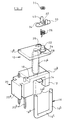
- the rotary solenoid arrangement illustrated in Figure 1 comprises a plastics molded support member 10 which includes an upper plate-like part 10a integrally connected to a lower plate-like part 10 b by a tubular region 10 c .
- the lower plate-like part 10 b is provided on its lower surface with a projection 12 including a downwardly facing re-entrant recess or opening 14.
- the upper and lower plate-like parts 10 a , 10 b are both provided with a pair of openings, one of the openings on each of the upper and lower plate-like parts 10 a , 10 b being aligned with the tubular part 10 c .
- a core 16 formed from a ferrous rod which is shaped so as to take a generally U-shaped form is arranged so that the limbs 16a, 16b of the core member 16 extend through the openings of the support member 10.
- the first limb 16a of the core 16 extends through the openings aligned with the tubular part 10 c , the second limb 10 b extending through both of the other openings provided in the upper and lower plate-like parts 10 a , 10 b .
- the lower, interconnecting part 16 c of the core member 16 is received as a snap-fit within the re-entrant recess 14 so as to secure the support member 10 to the core 16.
- the core 16 may alternatively be of sintered metal or take the form of a U-shaped casting.
- a coil (not shown) is wound around the tubular part 10 c of the support member 10, and it will be recognised that when the core 16 is secured to the support member 10 as described hereinbefore, the coil encircles the first limb 16 a of the core 16.
- a channel 18 is provided in the upper face of the lower plate-like part 10 b , the starting end of the coil wire being received within the channel 18.
- a connector arrangement 20 is integral with the lower plate-like part 10 b , the connector arrangement 20 including a region 20a shaped so as to be cooperable with a bracket for supporting the support member 10, in use, terminals 20 b also being molded into the connector arrangement 20, the terminals 20 b being soldered to respective ends of the wire forming the coil.
- the upper face of the upper plate-like part 10a is provided with a cylindrical projection 22 located centrally between the two openings of the upper plate-like part 10 a .
- An annular recess 24 is provided in the upper face of the upper plate-like part 10 a surrounding the projection 22.
- a spring 26 is received within the annular recess 24, an end of the spring 26 being received within a radially outwardly extending groove 28 extending from the annular recess 24.
- a ferrous armature 30 is rotatably mounted on the projection 22, the armature 30 including a central opening 32 through which the projection 22 extends.
- the armature 30 is further provided with a small opening 34 arranged to receive a second end of the spring 26.
- the armature 30 is secured to the projection 22 by means of a "spire washer” retaining clip 36 which is forced onto the projection 22 after the spring 26 and armature 30 have been correctly positioned.
- the positioning of the spring 26 and armature 30 is such that the armature 30 is biased towards a position in which an end thereof engages a stop 38 provided on the upper face of the upper plate-like part 10 a .
- suitable bearings may be provided to aid rotary movement of the armature 30, and the axial length of the opening in the armature 30 may be increased by incorporating a suitable bush to aid guidance of rotary motion.
- the ends of the limbs 16 a , 16 b are provided with part circular recesses 16 d .
- the armature 30 occupies a position in which an end thereof engages the stop 38 due to the action of the spring 26.
- the magnetic field due to the excitation of the coil attracts the armature 30, rotating the armature 30 towards a position in which the ends thereof lie adjacent the ends of the limbs 16a, 16b of the core, the ends of the armature 30 being located within the part-circular recesses 16 d .
- the armature 30 Upon de-energising the coil, the armature 30 returns to its initial position under the action of the spring 26.
- the armature 30 In order to enable motion of the armature 30 to be transmitted to an associated auxiliary device, the armature 30 is provided with lugs 40 which, in use, engage appropriate parts of the associated auxiliary device.
- the rotary solenoid illustrated in Figure 1 lends itself to automated assembly since once the coil has been wound on the tubular part 10 c of the support member 10 and the ends of the wire forming the coil have been soldered to the terminals 20 b , the remainder of the assembly process may be undertaken in a single assembly location.
- the core 16 is mounted in an appropriate jig, and the support member 10 is located over the limbs 16a, 16b of the core 16, the support member 10 being lowered until the intermediate part 16c of the core 16 is received within the re-entrant recess 14, securing the support member 10 to the core 16.
- the spring 26 is positioned around the projection 22 and received within the recess 24, an end of the spring 26 being received within the groove 28.
- the armature 30 and retaining clip 36 are then positioned on the projection 22. During each of these assembly steps, the core 16 is held within the jig, movement of the core 16 not being necessary.
- the rotary solenoid is of relatively simple construction, assembly of the rotary solenoid being relatively simple, and being suitable for use in an automated assembly arrangement.
- Figure 2 illustrates an arrangement which is similar to that of Figure 1, but in which the upper and lower plate-like parts 10 a , 10 b are of reduced length and only include apertures arranged to receive one of the limbs of the core 16.
- the integral tubular part 10 c interconnects the remaining one aperture in each of the upper and lower plate-like parts 10 a , 10 b .
- the method of assembly, and the operation of the rotary solenoid of Figure 2 are as described in Figure 1.
- the arrangement of Figure 2 has the advantage that the amount of material used in producing the support member 10 is reduced, but there may be the disadvantage that only one of the limbs of the core 16 is supported, thus the core may be susceptible to damage resulting in the separation of the limbs changing which may result in inefficient operation of the solenoid, or in the armature 30 engaging and possibly becoming trapped between, the limbs of the core 16.
- one of the upper and lower plate-like parts may be extended so as to guide both limbs of the core, the other of the plate-like parts only receiving one of the limbs.
- Figure 3 illustrates another arrangement which is similar to that of Figure 1 but in which the projection 12 is not provided on the lower surface of the lower plate-like part 10 b .
- a retaining clip 42 is pushed over the end of the second limb 16 b , the retaining clip 42 being received within a recess 44 provided in the upper surface of the upper plate-like part 10 a and surrounding the opening thereof through which the second limb 16 b extends.
- Figure 3 is identical to that of Figure 1, and it will be recognised that the assembly of the rotary solenoid of Figure 3 is similar to that of the solenoid of Figure 1, the assembly process including the additional step of locating the retaining clip 42 on the second limb 16 b of the core 16 in order to secure the core 16 to the support member 10.
- Figure 3 may be modified by arranging for the clip 42 to be positioned on the first limb 16a of the core 16, a suitable recess being provided in the upper face of the upper plate-like part 10 a in order to receive the clip 42, and if desired, a pair of such retaining clips may be used, one clip engaging each of the limbs of the core 16.
- a radially extending air gap exists between the armature 30 and the ends of the limbs 16a, 16 b of the core 16 when the coil is excited and the armature 30 moved so as to lie adjacent the ends of the core 16.
- the air gap may extend in a direction substantially parallel to the axis of rotation of the armature 30 as illustrated in Figure 4, and the modification illustrated in Figure 4 may be applied to any of the embodiments illustrated in Figures 1 to 3 or variations thereof.
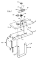
- Figures 5 and 6 illustrate an embodiment in which the plate-like parts 10 a , 10 b are of generally circular form and are interconnected by the tubular part which extends along the axis of the plate-like parts 10 a , 10 b .
- a coil is wound around the tubular part.
- One limb of the core 16 extends through the tubular part, the other limb being received by formations 50 provided on the plate-like parts 10 a , 10 b .
- the core 16 is secured in position by a projection including a re-entrant opening which is formed on the lower surface of the lower plate-like part 10 b as described hereinbefore.
- the upper plate-like part 10 a is provided with a projection 22 which is shaped to permit mounting of an armature 30 thereon in a snap-fit manner.
- a further similar projection 52 is provided on the upper plate-like part 10a and is used to mount a cam member 54 to the upper plate-like part 10 a .
- the cam member 54 includes a downwardly extending peg 56 which, in use, engages a spring 58 secured to the upper plate-like part 10a by formations 60 to bias the cam member 54 towards a rest position (illustrated in Figure 6).
- the spring 58 may comprise a length of spring wire or flat strip.
- the armature 30 includes upwardly extending rotationally symmetrical abutments 62, one of which engages the cam member 54 such that when the cam member 54 occupies its rest position, the armature 30 is pushed by the cam member 54 into engagement with a movement limiting stop 38 provided on the upper plate-like part 10 a .
- Energization of the coil causes movement of the armature 30 which, in turn, moves the cam member 54 against the action of the spring 60.
- the cam member 54 is shaped to amplify the relatively small movement of the armature 30 between its rest and energized positions.
- Figures 5 and 6 may be modified to include, for example, an axial rather than radial air gap as described with reference to Figure 4, and other modifications may be made to the device.
- the core may be secured to the support member using suitable adhesives or may be an interference fit with the support member. Further, rotational movement of the support member with respect to the core may be restricted by forming the core from a ferrous rod or bar of non-circular cross-section, the openings provided in the support member being similarly shaped.
Landscapes
- Physics & Mathematics (AREA)
- Electromagnetism (AREA)
- Engineering & Computer Science (AREA)
- Power Engineering (AREA)
- Electromagnets (AREA)
- Reciprocating, Oscillating Or Vibrating Motors (AREA)
- Connection Of Motors, Electrical Generators, Mechanical Devices, And The Like (AREA)
Applications Claiming Priority (2)
| Application Number | Priority Date | Filing Date | Title |
|---|---|---|---|
| GB9621334 | 1996-10-12 | ||
| GBGB9621334.3A GB9621334D0 (en) | 1996-10-12 | 1996-10-12 | Rotary solenoid |
Publications (2)
| Publication Number | Publication Date |
|---|---|
| EP0836202A2 true EP0836202A2 (fr) | 1998-04-15 |
| EP0836202A3 EP0836202A3 (fr) | 1998-08-05 |
Family
ID=10801348
Family Applications (1)
| Application Number | Title | Priority Date | Filing Date |
|---|---|---|---|
| EP97308061A Ceased EP0836202A3 (fr) | 1996-10-12 | 1997-10-10 | Solénoide rotatif |
Country Status (4)
| Country | Link |
|---|---|
| US (1) | US6078236A (fr) |
| EP (1) | EP0836202A3 (fr) |
| JP (1) | JPH10270241A (fr) |
| GB (1) | GB9621334D0 (fr) |
Families Citing this family (4)
| Publication number | Priority date | Publication date | Assignee | Title |
|---|---|---|---|---|
| US6756873B2 (en) | 2000-09-13 | 2004-06-29 | Saia-Burgess Inc. | Hybrid rotary actuator |
| UA57881C2 (uk) * | 2001-12-29 | 2003-07-15 | Микола Сергійович Бабич | Спосіб керування магнітним потоком електромагніта і електромагніт(варіанти), що реалізує спосіб. |
| JP4069838B2 (ja) * | 2003-09-10 | 2008-04-02 | セイコーエプソン株式会社 | 表示ドライバ、電気光学装置及び表示ドライバの制御方法 |
| CN101681710A (zh) * | 2007-06-19 | 2010-03-24 | 胜美达集团株式会社 | 磁性元件及使用磁性元件的天线装置 |
Family Cites Families (10)
| Publication number | Priority date | Publication date | Assignee | Title |
|---|---|---|---|---|
| DE1932679A1 (de) * | 1969-06-27 | 1971-01-07 | Licentia Gmbh | Gleichstrom-Drehankermagnet |
| US3548352A (en) * | 1969-08-06 | 1970-12-15 | Atomic Energy Commission | Actuating device |
| US3783312A (en) * | 1973-01-15 | 1974-01-01 | Singer Co | Viscous deceleration damped incremental position motor |
| GB1452332A (en) * | 1973-06-29 | 1976-10-13 | Best Products Ltd | Electric toasters |
| US4392423A (en) * | 1978-02-08 | 1983-07-12 | Hitachi, Ltd. | Printing hammer driving apparatus |
| US4216849A (en) * | 1978-06-12 | 1980-08-12 | Kelsey Hayes Co. | Electromagnets for brakes and clutches |
| GB2062356A (en) * | 1979-10-30 | 1981-05-20 | Wessex Advanced Switching Prod | Multi-position electromagnetic actuator |
| US4642594A (en) * | 1984-08-10 | 1987-02-10 | Siemens Energy & Automation, Inc. | U-shaped solid magnetic core with at least one opening through the midsection thereof |
| JPH03183347A (ja) * | 1989-12-08 | 1991-08-09 | Apuritsukusu Kk | ロータリーソレノイド |
| US5703555A (en) * | 1995-04-25 | 1997-12-30 | Itt Automotive Electrical Systems Inc. | Rotary actuator |
-
1996
- 1996-10-12 GB GBGB9621334.3A patent/GB9621334D0/en active Pending
-
1997
- 1997-10-10 US US08/948,946 patent/US6078236A/en not_active Expired - Fee Related
- 1997-10-10 EP EP97308061A patent/EP0836202A3/fr not_active Ceased
- 1997-10-13 JP JP9278945A patent/JPH10270241A/ja active Pending
Also Published As
| Publication number | Publication date |
|---|---|
| US6078236A (en) | 2000-06-20 |
| EP0836202A3 (fr) | 1998-08-05 |
| JPH10270241A (ja) | 1998-10-09 |
| GB9621334D0 (en) | 1996-11-27 |
Similar Documents
| Publication | Publication Date | Title |
|---|---|---|
| US5587693A (en) | Polarized electromagnetic relay | |
| EP0784330B1 (fr) | Relais électromagnétique | |
| US5952904A (en) | Relay adjustment structure and methods | |
| JP3378002B2 (ja) | 電磁リレー | |
| US6078236A (en) | Rotary solenoid | |
| US5382934A (en) | Electromagnetic changeover relay | |
| US6995487B2 (en) | Endplay adjustment and bearing decoupling in an electric motor | |
| JPH05166449A (ja) | 電磁継電器 | |
| US4801910A (en) | Magnetic actuating mechanism | |
| US6864609B2 (en) | Low noise motor with one-piece frame and torsion flux ring | |
| JPH05506957A (ja) | 電磁切換装置および該装置を製造する方法 | |
| US6998746B2 (en) | Electric motor sleeve bearing assembly with acoustic/vibration decoupling and endplay adjustment | |
| CN1129940C (zh) | 电磁继电器 | |
| JP3335333B2 (ja) | プランジャ | |
| JPH0690901B2 (ja) | 接触器駆動用電磁石装置 | |
| JPH10255630A (ja) | 電磁継電器 | |
| JP3618503B2 (ja) | ソレノイド装置 | |
| JP3136974B2 (ja) | 電磁ソレノイド | |
| JPH08289529A (ja) | 電磁駆動装置 | |
| JP5246145B2 (ja) | 電磁継電器の接点接触圧調整方法 | |
| JP3360853B2 (ja) | 小型プランジャ | |
| JP2000324788A (ja) | モータ | |
| WO1998031036A1 (fr) | Dispositif de retenue d'un aimant de relais | |
| JP2000021279A (ja) | 電磁継電器とその製造方法 | |
| JPS6062102A (ja) | ソレノイド装置 |
Legal Events
| Date | Code | Title | Description |
|---|---|---|---|
| PUAI | Public reference made under article 153(3) epc to a published international application that has entered the european phase |
Free format text: ORIGINAL CODE: 0009012 |
|
| AK | Designated contracting states |
Kind code of ref document: A2 Designated state(s): DE FR GB IT |
|
| AX | Request for extension of the european patent |
Free format text: AL;LT;LV;RO;SI |
|
| PUAL | Search report despatched |
Free format text: ORIGINAL CODE: 0009013 |
|
| AK | Designated contracting states |
Kind code of ref document: A3 Designated state(s): AT BE CH DE DK ES FI FR GB GR IE IT LI LU MC NL PT SE |
|
| AX | Request for extension of the european patent |
Free format text: AL;LT;LV;RO;SI |
|
| 17P | Request for examination filed |
Effective date: 19990115 |
|
| AKX | Designation fees paid |
Free format text: DE FR GB IT |
|
| RBV | Designated contracting states (corrected) |
Designated state(s): DE FR GB IT |
|
| 17Q | First examination report despatched |
Effective date: 20000324 |
|
| GRAG | Despatch of communication of intention to grant |
Free format text: ORIGINAL CODE: EPIDOS AGRA |
|
| STAA | Information on the status of an ep patent application or granted ep patent |
Free format text: STATUS: THE APPLICATION HAS BEEN REFUSED |
|
| 18R | Application refused |
Effective date: 20020331 |