EP0836208A2 - In eine Vergussmasse eingebettetes Schaltelement und Verfahren zu seiner Herstellung - Google Patents
In eine Vergussmasse eingebettetes Schaltelement und Verfahren zu seiner Herstellung Download PDFInfo
- Publication number
- EP0836208A2 EP0836208A2 EP97115957A EP97115957A EP0836208A2 EP 0836208 A2 EP0836208 A2 EP 0836208A2 EP 97115957 A EP97115957 A EP 97115957A EP 97115957 A EP97115957 A EP 97115957A EP 0836208 A2 EP0836208 A2 EP 0836208A2
- Authority
- EP
- European Patent Office
- Prior art keywords
- trough
- potting
- casting
- filling
- switching element
- Prior art date
- Legal status (The legal status is an assumption and is not a legal conclusion. Google has not performed a legal analysis and makes no representation as to the accuracy of the status listed.)
- Granted
Links
- 238000004382 potting Methods 0.000 title claims description 55
- 150000001875 compounds Chemical class 0.000 title claims description 27
- 238000000034 method Methods 0.000 title claims description 8
- 238000005266 casting Methods 0.000 claims abstract description 28
- 238000005429 filling process Methods 0.000 claims abstract description 9
- 238000007789 sealing Methods 0.000 claims description 10
- 229920003002 synthetic resin Polymers 0.000 claims description 3
- 239000000057 synthetic resin Substances 0.000 claims description 3
- 230000000630 rising effect Effects 0.000 claims description 2
- 239000011347 resin Substances 0.000 abstract 2
- 229920005989 resin Polymers 0.000 abstract 2
- 239000007788 liquid Substances 0.000 description 5
- 238000005259 measurement Methods 0.000 description 3
- IUSARDYWEPUTPN-OZBXUNDUSA-N (2r)-n-[(2s,3r)-4-[[(4s)-6-(2,2-dimethylpropyl)spiro[3,4-dihydropyrano[2,3-b]pyridine-2,1'-cyclobutane]-4-yl]amino]-3-hydroxy-1-[3-(1,3-thiazol-2-yl)phenyl]butan-2-yl]-2-methoxypropanamide Chemical compound C([C@H](NC(=O)[C@@H](C)OC)[C@H](O)CN[C@@H]1C2=CC(CC(C)(C)C)=CN=C2OC2(CCC2)C1)C(C=1)=CC=CC=1C1=NC=CS1 IUSARDYWEPUTPN-OZBXUNDUSA-N 0.000 description 2
- 229940125807 compound 37 Drugs 0.000 description 2
- 238000005553 drilling Methods 0.000 description 2
- 239000000463 material Substances 0.000 description 2
- 239000002689 soil Substances 0.000 description 2
- 230000001174 ascending effect Effects 0.000 description 1
- 230000015572 biosynthetic process Effects 0.000 description 1
- 230000009194 climbing Effects 0.000 description 1
- 238000007796 conventional method Methods 0.000 description 1
- 230000001419 dependent effect Effects 0.000 description 1
- 238000006073 displacement reaction Methods 0.000 description 1
- 230000003287 optical effect Effects 0.000 description 1
- 230000000149 penetrating effect Effects 0.000 description 1
- 230000003068 static effect Effects 0.000 description 1
- 239000006228 supernatant Substances 0.000 description 1
Images


Classifications
-
- H—ELECTRICITY
- H01—ELECTRIC ELEMENTS
- H01H—ELECTRIC SWITCHES; RELAYS; SELECTORS; EMERGENCY PROTECTIVE DEVICES
- H01H11/00—Apparatus or processes specially adapted for the manufacture of electric switches
-
- H—ELECTRICITY
- H01—ELECTRIC ELEMENTS
- H01H—ELECTRIC SWITCHES; RELAYS; SELECTORS; EMERGENCY PROTECTIVE DEVICES
- H01H9/00—Details of switching devices, not covered by groups H01H1/00 - H01H7/00
- H01H9/02—Bases, casings, or covers
- H01H9/04—Dustproof, splashproof, drip-proof, waterproof, or flameproof casings
-
- Y—GENERAL TAGGING OF NEW TECHNOLOGICAL DEVELOPMENTS; GENERAL TAGGING OF CROSS-SECTIONAL TECHNOLOGIES SPANNING OVER SEVERAL SECTIONS OF THE IPC; TECHNICAL SUBJECTS COVERED BY FORMER USPC CROSS-REFERENCE ART COLLECTIONS [XRACs] AND DIGESTS
- Y10—TECHNICAL SUBJECTS COVERED BY FORMER USPC
- Y10T—TECHNICAL SUBJECTS COVERED BY FORMER US CLASSIFICATION
- Y10T29/00—Metal working
- Y10T29/49—Method of mechanical manufacture
- Y10T29/49002—Electrical device making
- Y10T29/49105—Switch making
Definitions
- the invention relates to an at least partially embedded in a potting compound Switching element with a casting trough and a method for watertight Sealing of the switching element, preferably the connection area of electrical connecting cables.
- the sealing of electrical switching elements by potting with waterproof Potting compounds are generally known and are used in a variety of ways. Not only the entire switching components are in one housing shed, but very often only the electrical connection lines in the area of the connecting pins. For this purpose it is in the area of the connecting pins a potting trough is provided, either in one piece or attachable is and filled in a conventional manner from above with the potting compound is filled by a dosing unit. During the filling process the dispensing needle guided such that the filling process from the tub floor as evenly as possible in the direction of the tub edge. To do this both One-component and two-component materials, preferably in Form of low-viscosity synthetic resins, used, which harden after filling or cured under the influence of heat.
- FIG. 1 The one shown in FIG. 1 is simple for potting microswitches Device usual in which several switches 10 with attached or molded Potting trough 11 arranged side by side in a holder 12 will.
- a wiring harness 15 is already soldered to pins 16, so that with a metering unit 17, the metering needle 18 from potting tub to potting tub is guided to the tubs from the bottom up with the potting compound replenish.
- the invention is therefore based on the object of providing measures with which switching elements either partially or entirely in one housing or a potting pan can be potted, the housing parts in such a way should be designed so that a fully automated casting is possible and Air pockets or air bubbles are largely avoided.
- the potting trough is provided with a filling hole, which in the lowest point of the Casting trough is attached that the filling hole with one to be dosed Potting compound is provided with detachable bottom skin, and that the potting trough has a measuring opening on a side facing away from the filling bore Has.
- the potting trough can surround the switching element in one piece or on the switching element can be placed in the form of a cap on which the filling hole and the measurement opening and wiring harness opening opposite this are attached.
- the switching element preferably consists of a switch in the case of the connecting pins protrude into the potting pan and in which also the connecting pins receiving holes also exploded with the pin assembly Floor skins are provided.
- the filling hole is advantageously conical to the center of the bottom running blind hole, the bottom center as a thin-walled Soil skin is formed.
- the diameter of the filling hole is smaller than the outside diameter the dispensing needle, which preferably has a conical surface in the filling hole intervenes.
- the method according to the invention for the watertight sealing of switching elements or to seal the connection area of electrical switching elements, especially microswitches, by casting one on the base area provided, the connections surrounding potting pan, in which the casting compound, preferably a one- or two-component synthetic resin, with a dispensing needle is filled in the potting trough, provides that the switching element is used in a holder such that one on the wall of the Pouring trough fitted and sealed with a bottom skin filling hole is arranged at the deepest area of the potting volume and that the dispensing needle attached to the filling hole and the potting compound under pressure in the potting trough is pressed, the bottom skin being blown up.
- a further embodiment of the method provides that the potting trough to a measuring opening of parts of the holder or through a cap-like Training is closed.
- the height of the mirror rising in the casting trough Potting compound scanned through the measuring opening with a laser beam and thus controls the level and controls the filling process becomes.
- FIG. 2 is a schematic representation of part of an automatic device Shedding the connection area of a microswitch shown.
- This device comprises a holder 20 of preferably L-shaped Form, which carries a sealing plate 21 on the vertical wall against which the open side of the potting trough 11 of a microswitch 10 with the help a pressure stamp 22 is pressed.
- the potting trough 11 in one piece with the bottom part of the switch housing executed.
- connecting pins 25 protrude, which one Wiring harness 26 is soldered.
- the wiring harness is preferably such led that he within the potting tray 11 fixed in the bracket 20th runs vertically and protrudes from the cast trough at the upper end.
- the potting trough has a filling bore 28 in the wall at the lower end, which is located at the lowest point of the casting volume and is in the top wall with a measuring opening 29, on which a Laser 30 provided in the device is aligned such that its Laser beam 31 penetrate through the measuring opening 29 into the interior of the casting trough can.
- the alignment of the laser beam is such that it is approximately perpendicular to the ascending level of the sealing compound as explained below runs.
- the device is further provided with a dosing unit, which is not shown is and the dispensing needle are placed on the filling bore 28 can.
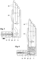
- FIG. 3 is a view of the open side of the tundish in Partial section through the filling bore 28.
- This filling hole is a blind hole executed with a tapered bottom of the bore, whereby this bottom of the hole is very thin in the area of the center and a bottom skin 27 forms, which keeps the filling bore 28 closed.
- the Illustration can be seen that the strands soldered to the connecting pins 25 of the wiring harness 26 protrude upwards onto the casting trough 11. The There is a measurement opening, which does not appear from the illustration the wiring harness 26.
- the metering needle 35 has a tapered tip pressed against a sealing edge 36 of the filling bore 28 and, as in FIG. 4 emerges, the casting compound 37 pressed into the casting trough 11.
- the air-free Backfilling is ensured due to the fact that a low viscosity Potting compound is supplied via the metering needle.
- Laser beam 31 continuously scans the liquid level during the pouring by continuously increasing the distance to the surface of the sealing compound is measured. With the help of these measurement results, the filling process Controlled and canceled as soon as the liquid level is the highest The measuring opening at the point is reached or filled. This level is in the Usually in the area of the height of the exit of the cable harness 26 from the casting trough 11.
- the metering unit After reaching the specified level at the wiring harness exit the metering unit switches off the conveyance of the liquid casting compound 37, so that due to the pressure relief and the static pressure of the still liquid potting compound in the potting pan closes the bottom skin, so that from the filling bore 28 no potting compound can escape.
- This closing the Filling drilling is favored by the conical shape of the drilling base, because when the potting compound is pressed into the blown-up soil a restoring force results from the material elasticity.
- the measures of the invention can be a semi-automatic or fully automatic Filling of switching elements or areas of such Switching elements take place, the backfilling due to the scanning of the Liquid level controlled very precisely and precisely with the help of the laser beam can be. This allows shorter cycle times and one ensure even introduction of the potting compound into the potting trough, without protrusions that are scraped off by expensive rework or must be removed. In addition, there is no backfilling due to turbulence The formation of bubbles or voids is guaranteed.
Landscapes
- Engineering & Computer Science (AREA)
- Manufacturing & Machinery (AREA)
- Casting Or Compression Moulding Of Plastics Or The Like (AREA)
- Switches That Are Operated By Magnetic Or Electric Fields (AREA)
- Encapsulation Of And Coatings For Semiconductor Or Solid State Devices (AREA)
- Manufacture Of Switches (AREA)
Abstract
Description
- Fig. 1
- eine Füllvorrichtung nach dem Stand der Technik;
- Fig. 2
- eine Füllvorrichtung zur Durchführung des erfindungsgemäßen Verfahrens bei der Anwendung für einen Mikroschalter;
- Fig. 3, 3 und 5
- schematische Darstellungen drei aufeinanderfolgender Phasen des Füllvorganges.
Claims (10)
- In eine Vergußmasse zumindest teilweise eingebettetes Schaltelement in einer Vergußwanne,
dadurch gekennzeichnet,daß die Vergußwanne (11) mit einer Füllbohrung (28) versehen ist,daß die Füllbohrung (28) mit einer durch eine einzudosierende Vergußmasse (37) aufsprengbaren Bodenhaut (27) versehen ist unddaß die Vergußwanne (11) an einer der Füllbohrung (28) abgewandten Seite eine Meßöffnung (29) hat. - Schaltelemente nach Anspruch 1,
dadurch gekennzeichnet,daß die Vergußwanne (11) mit dem Schaltelement (10) einstückig ausgebildet ist. - Schaltelement nach Anspruch 1,
dadurch gekennzeichnet,daß die Vergußwanne (11) eine auf das Schaltelement (10) aufsetzbare Kappe hat, an welcher die Füllbohrung (28) und die dieser gegenüberliegenden Meßöffnung (27) sowie Kabelbaumöffnung angebracht sind. - Schaltelement nach einem der Ansprüche 1 bis 3,
dadurch gekennzeichnet,daß das Schaltelement (10) ein Schalter ist, bei dem Anschlußstifte (16) in die Vergußwanne (11) ragen, unddaß die die Anschlußstifte aufnehmenden Bohrungen im Gehäuse ebenfalls mit bei der Stiftmontage aufsprengbaren Bodenhäuten versehen sind. - Schaltelemente nach einem oder mehreren der Ansprüche 1 bis 4,
dadurch gekennzeichnet,daß die Füllbohrung (28) als Sackbohrung kegelförmig zur Bodenmitte verläuft, welche die Bodenhaut (27) bildet. - Schaltelemente nach Anspruch 5,
dadurch gekennzeichnet,daß der Durchmesser der Füllbohrung (28) kleiner als der Außendurchmesser der Dosiernadel (35) ist. - Schaltelement nach Anspruch 6,
dadurch gekennzeichnet,daß die Dosiernadel (35) mit einer Kegelspitze in die Füllbohrung (28) abdichtend eingreift. - Verfahren zur wasserdichten Abdichtung von Schaltelementen bzw. des Anschlußbereiches von elektrischen Schaltelementen, insbesondere von Mikroschaltern, durch Vergießen einer am Sockelbereich vorgesehenen, die Anschlüsse aufnehmenden Vergußwanne, bei welchem die Vergußmasse (vorzugsweise ein Ein- oder Zweikomponentenkunstharz) mit einer Dosiernadel in die Vergußwanne gefüllt wird,
dadurch gekennzeichnet,daß das Schaltelement in eine Halterung (20) derart eingesetzt wird, daß eine an der Wandung der Vergußmasse (11) angebrachte und mit einer Bodenhaut (27) versehene Füllbohrung (28) am tiefsten Bereich des Vergußvolumens angeordnet ist und daß die Dosiernadel (35) an die Füllbohrung (28) angesetzt und die Vergußmasse (37) durch Druck in die Vergußwanne (11) gepreßt wird, wobei die Bodenhaut (27) gesprengt wird. - Verfahren nach Anspruch 8,
dadurch gekennzeichnet,daß die Vergußwanne (11) bis auf eine Meßöffnung (29) von Teilen der Halterung bzw. durch eine kappenartige Ausbildung der Vergußwanne verschlossen wird. - Verfahren nach Anspruch 9 oder 10,
dadurch gekennzeichnet,daß die Höhe des Spiegels der in der Vergußwanne aufsteigenden Vergußmasse (37) mit einem Laserstrahl (31) durch die Meßöffnung (29) abgetastet und der Füllstand kontrolliert sowie der Füllvorgang gesteuert wird.
Applications Claiming Priority (2)
| Application Number | Priority Date | Filing Date | Title |
|---|---|---|---|
| DE19642403A DE19642403A1 (de) | 1996-10-14 | 1996-10-14 | In eine Vergußmasse eingebettetes Schaltelement und Verfahren zu seiner Herstellung |
| DE19642403 | 1996-10-14 |
Publications (3)
| Publication Number | Publication Date |
|---|---|
| EP0836208A2 true EP0836208A2 (de) | 1998-04-15 |
| EP0836208A3 EP0836208A3 (de) | 1999-01-27 |
| EP0836208B1 EP0836208B1 (de) | 2003-01-02 |
Family
ID=7808746
Family Applications (1)
| Application Number | Title | Priority Date | Filing Date |
|---|---|---|---|
| EP97115957A Expired - Lifetime EP0836208B1 (de) | 1996-10-14 | 1997-09-12 | Vergusswanne mit einem zumindest teilweise in Vergussmasse eingebetteten Schaltelement |
Country Status (3)
| Country | Link |
|---|---|
| US (1) | US5890586A (de) |
| EP (1) | EP0836208B1 (de) |
| DE (2) | DE19642403A1 (de) |
Families Citing this family (3)
| Publication number | Priority date | Publication date | Assignee | Title |
|---|---|---|---|---|
| JP2005235487A (ja) | 2004-02-18 | 2005-09-02 | Yazaki Corp | 電線ジョイント部の防水方法 |
| US7285739B1 (en) * | 2006-03-31 | 2007-10-23 | Zippy Technology Corp. | Waterproof structure for switch pins |
| US8089014B2 (en) * | 2006-09-29 | 2012-01-03 | Hokuriku Electric Industry Co., Ltd. | Waterproof push button switch |
Family Cites Families (13)
| Publication number | Priority date | Publication date | Assignee | Title |
|---|---|---|---|---|
| FR1547824A (fr) * | 1966-11-10 | 1968-11-29 | électro-aimant, destiné plus particulièrement à la commande de vannes hydrauliques, et son procédé de fabrication | |
| US3829263A (en) * | 1972-07-10 | 1974-08-13 | Rion Co | Apparatus for reduced pressure casting of synthetic resins |
| US4204231A (en) * | 1978-03-20 | 1980-05-20 | Clinton Electronics Corporation | Cathode ray tube with laminated panel and method of making same |
| DE3226746C1 (de) * | 1982-07-15 | 1984-01-26 | Siemens AG, 1000 Berlin und 8000 München | Verfahren zum Giessen eines Kunststoffkoerpers,insbesondere eines Schreibwerkes eines Tintenschreibers |
| DE3308821C2 (de) * | 1983-03-12 | 1985-03-07 | Standard Elektrik Lorenz Ag, 7000 Stuttgart | Elektromagnetisches Relais |
| DE3308791C2 (de) * | 1983-03-12 | 1986-08-21 | Standard Elektrik Lorenz Ag, 7000 Stuttgart | Verfahren zur Herstellung eines dichten elektromagnetischen Relais |
| JPS6429726U (de) * | 1987-08-14 | 1989-02-22 | ||
| US4895998A (en) * | 1988-08-15 | 1990-01-23 | Mcneil (Ohio) Corporation | Encapsulated electrical component and method of making same |
| DE3827638A1 (de) * | 1988-08-16 | 1990-03-08 | Baer Elektrowerke Gmbh & Co Kg | Elektrischer schnappschalter |
| DE9011926U1 (de) * | 1990-08-17 | 1990-11-15 | Burgess GmbH, 2900 Oldenburg | Elektrischer Kleinstschalter |
| FR2674177B1 (fr) * | 1991-03-20 | 1993-06-25 | Telemecanique | Procede pour noyer dans de la resine l'interieur d'un appareil electrique tel que detecteur de proximite, et appareil electrique s'y rapportant. |
| FR2698757B1 (fr) * | 1992-11-27 | 1995-02-17 | Sextant Avionique | Capot de protection de cosse d'un boîtier électrique étanche. |
| DE4422857C2 (de) * | 1994-06-30 | 1996-10-17 | A B Elektronik Gmbh | Schaltvorrichtung und Verfahren zur Herstellung einer Sockelplatteneinheit hierfür |
-
1996
- 1996-10-14 DE DE19642403A patent/DE19642403A1/de not_active Withdrawn
-
1997
- 1997-09-12 DE DE59709049T patent/DE59709049D1/de not_active Expired - Lifetime
- 1997-09-12 EP EP97115957A patent/EP0836208B1/de not_active Expired - Lifetime
- 1997-10-14 US US08/949,835 patent/US5890586A/en not_active Expired - Fee Related
Also Published As
| Publication number | Publication date |
|---|---|
| DE19642403A1 (de) | 1998-04-16 |
| DE59709049D1 (de) | 2003-02-06 |
| US5890586A (en) | 1999-04-06 |
| EP0836208B1 (de) | 2003-01-02 |
| EP0836208A3 (de) | 1999-01-27 |
Similar Documents
| Publication | Publication Date | Title |
|---|---|---|
| DE2942258C2 (de) | ||
| DE69621874T2 (de) | Injektion eines Sanierungsmediums in Beton | |
| EP0836208B1 (de) | Vergusswanne mit einem zumindest teilweise in Vergussmasse eingebetteten Schaltelement | |
| DE3400263C2 (de) | ||
| DE1460317A1 (de) | Verfahren und Vorrichtung zum Impraegnieren von Faser- oder Fadenstraengen | |
| DE3539252C2 (de) | Näherungsschalter und Verfahren zu seiner Herstellung | |
| DE3341283A1 (de) | Behaelter zum ausspritzen eines bindemittels fuer die verankerung eines befestigungselementes in einem bohrloch | |
| DE102009008947A1 (de) | Verfahren zur Herstellung einer LED-Leuchte | |
| DE3023126A1 (de) | Halbleiter-leuchtanzeigevorrichtung | |
| WO1991016806A1 (de) | Verfahren zum aufbringen einer kunststoffschutzschicht sowie vorrichtung zur durchführung des verfahrens | |
| DE2900763C2 (de) | Flüssigkeitsdichte mit einem Flachstecker ausgerüstete Durchführung | |
| DE3129348A1 (de) | Manuell betaetigbare dosierspritze fuer fluessigkeiten oder plastische massen, insbesondere fuer dentalzwecke | |
| DE7539561U (de) | Deckel fuer bremsfluessigkeitsbehaelter mit einem niveauindikator | |
| EP1127364B1 (de) | Drehknebel zur betätigung des stelltriebes eines potentiometers | |
| DE4330977A1 (de) | Gehäuse aus Kunststoff, insbesondere zum Aufnehmen elektrischer Bauteile | |
| DE3308821C2 (de) | Elektromagnetisches Relais | |
| DE3234964C2 (de) | ||
| DE2023238B2 (de) | Verfahren und Vorrichtung zum Imprägnieren von Mauerwerk od.dgl | |
| DE3203944A1 (de) | Gehaeuse fuer einen naeherungsschalter und verfahren zu dessen herstellung | |
| DE3011132A1 (de) | Mischkopf zum vermischen und austragen von wenigstens zwei fliessfaehigen materialkomponenten | |
| DE2659220C3 (de) | Einrichtung zur Messung der Filtriereigenschaften von Papierbrei | |
| EP0094643A2 (de) | Giessgerät für Dentalgussteile | |
| DE3902383A1 (de) | Vorrichtung zum auftragen von spachtelmassen | |
| DE102022128732B3 (de) | Elektronikgehäuse zur Einhausung einer elektronischen Baugruppe sowie Verfahren zum Vergießen einer elektronischen Baugruppe | |
| WO2003054311A1 (de) | Vorrichtung zur abgabe eines flüssigen wirkstoffs in ein spülwasser |
Legal Events
| Date | Code | Title | Description |
|---|---|---|---|
| PUAI | Public reference made under article 153(3) epc to a published international application that has entered the european phase |
Free format text: ORIGINAL CODE: 0009012 |
|
| AK | Designated contracting states |
Kind code of ref document: A2 Designated state(s): DE FR GB IT |
|
| PUAL | Search report despatched |
Free format text: ORIGINAL CODE: 0009013 |
|
| AK | Designated contracting states |
Kind code of ref document: A3 Designated state(s): AT BE CH DE DK ES FI FR GB GR IE IT LI LU MC NL PT SE |
|
| 17P | Request for examination filed |
Effective date: 19990722 |
|
| AKX | Designation fees paid |
Free format text: DE FR GB IT |
|
| 17Q | First examination report despatched |
Effective date: 20010808 |
|
| GRAG | Despatch of communication of intention to grant |
Free format text: ORIGINAL CODE: EPIDOS AGRA |
|
| GRAG | Despatch of communication of intention to grant |
Free format text: ORIGINAL CODE: EPIDOS AGRA |
|
| GRAH | Despatch of communication of intention to grant a patent |
Free format text: ORIGINAL CODE: EPIDOS IGRA |
|
| RTI1 | Title (correction) |
Free format text: CONTAINER FOR A SWITCHING DEVICE ENCAPSULATED IN A POTTING COMPOUND |
|
| GRAH | Despatch of communication of intention to grant a patent |
Free format text: ORIGINAL CODE: EPIDOS IGRA |
|
| GRAA | (expected) grant |
Free format text: ORIGINAL CODE: 0009210 |
|
| AK | Designated contracting states |
Kind code of ref document: B1 Designated state(s): DE FR GB IT |
|
| PG25 | Lapsed in a contracting state [announced via postgrant information from national office to epo] |
Ref country code: IT Free format text: LAPSE BECAUSE OF FAILURE TO SUBMIT A TRANSLATION OF THE DESCRIPTION OR TO PAY THE FEE WITHIN THE PRE;WARNING: LAPSES OF ITALIAN PATENTS WITH EFFECTIVE DATE BEFORE 2007 MAY HAVE OCCURRED AT ANY TIME BEFORE 2007. THE CORRECT EFFECTIVE DATE MAY BE DIFFERENT FROM THE ONE RECORDED.SCRIBED TIME-LIMIT Effective date: 20030102 Ref country code: GB Free format text: LAPSE BECAUSE OF FAILURE TO SUBMIT A TRANSLATION OF THE DESCRIPTION OR TO PAY THE FEE WITHIN THE PRESCRIBED TIME-LIMIT Effective date: 20030102 Ref country code: FR Free format text: LAPSE BECAUSE OF FAILURE TO SUBMIT A TRANSLATION OF THE DESCRIPTION OR TO PAY THE FEE WITHIN THE PRESCRIBED TIME-LIMIT Effective date: 20030102 |
|
| REG | Reference to a national code |
Ref country code: GB Ref legal event code: FG4D Free format text: 20030102:NOT ENGLISH |
|
| REF | Corresponds to: |
Ref document number: 59709049 Country of ref document: DE Date of ref document: 20030206 Kind code of ref document: P |
|
| GBV | Gb: ep patent (uk) treated as always having been void in accordance with gb section 77(7)/1977 [no translation filed] |
Effective date: 20030102 |
|
| PLBE | No opposition filed within time limit |
Free format text: ORIGINAL CODE: 0009261 |
|
| STAA | Information on the status of an ep patent application or granted ep patent |
Free format text: STATUS: NO OPPOSITION FILED WITHIN TIME LIMIT |
|
| EN | Fr: translation not filed | ||
| 26N | No opposition filed |
Effective date: 20031003 |
|
| PGFP | Annual fee paid to national office [announced via postgrant information from national office to epo] |
Ref country code: DE Payment date: 20090910 Year of fee payment: 13 |
|
| REG | Reference to a national code |
Ref country code: DE Ref legal event code: R119 Ref document number: 59709049 Country of ref document: DE Effective date: 20110401 |
|
| PG25 | Lapsed in a contracting state [announced via postgrant information from national office to epo] |
Ref country code: DE Free format text: LAPSE BECAUSE OF NON-PAYMENT OF DUE FEES Effective date: 20110401 |