EP0836218B1 - Ecran actif de génération d'un plasma pour la pulvérisation - Google Patents
Ecran actif de génération d'un plasma pour la pulvérisation Download PDFInfo
- Publication number
- EP0836218B1 EP0836218B1 EP97307864A EP97307864A EP0836218B1 EP 0836218 B1 EP0836218 B1 EP 0836218B1 EP 97307864 A EP97307864 A EP 97307864A EP 97307864 A EP97307864 A EP 97307864A EP 0836218 B1 EP0836218 B1 EP 0836218B1
- Authority
- EP
- European Patent Office
- Prior art keywords
- shield
- conductive
- shield wall
- coil
- plasma
- Prior art date
- Legal status (The legal status is an assumption and is not a legal conclusion. Google has not performed a legal analysis and makes no representation as to the accuracy of the status listed.)
- Expired - Lifetime
Links
- 238000004544 sputter deposition Methods 0.000 title description 8
- 239000000463 material Substances 0.000 claims description 78
- 238000000151 deposition Methods 0.000 claims description 34
- 230000008021 deposition Effects 0.000 claims description 33
- 238000000034 method Methods 0.000 claims description 24
- 239000000758 substrate Substances 0.000 claims description 20
- 238000004804 winding Methods 0.000 claims description 16
- 239000004020 conductor Substances 0.000 claims description 9
- 238000005520 cutting process Methods 0.000 claims description 7
- 230000008878 coupling Effects 0.000 claims description 6
- 238000010168 coupling process Methods 0.000 claims description 6
- 238000005859 coupling reaction Methods 0.000 claims description 6
- 230000000903 blocking effect Effects 0.000 claims 2
- 230000001419 dependent effect Effects 0.000 claims 1
- 210000002381 plasma Anatomy 0.000 description 56
- 239000000919 ceramic Substances 0.000 description 9
- 230000001965 increasing effect Effects 0.000 description 9
- RTAQQCXQSZGOHL-UHFFFAOYSA-N Titanium Chemical compound [Ti] RTAQQCXQSZGOHL-UHFFFAOYSA-N 0.000 description 7
- 239000010936 titanium Substances 0.000 description 7
- 229910052719 titanium Inorganic materials 0.000 description 7
- 229910052751 metal Inorganic materials 0.000 description 6
- 239000002184 metal Substances 0.000 description 6
- 230000002829 reductive effect Effects 0.000 description 6
- 230000015572 biosynthetic process Effects 0.000 description 5
- 150000002500 ions Chemical class 0.000 description 5
- 230000002411 adverse Effects 0.000 description 4
- 230000003466 anti-cipated effect Effects 0.000 description 4
- 239000003990 capacitor Substances 0.000 description 4
- 230000003247 decreasing effect Effects 0.000 description 4
- NJPPVKZQTLUDBO-UHFFFAOYSA-N novaluron Chemical compound C1=C(Cl)C(OC(F)(F)C(OC(F)(F)F)F)=CC=C1NC(=O)NC(=O)C1=C(F)C=CC=C1F NJPPVKZQTLUDBO-UHFFFAOYSA-N 0.000 description 4
- 239000004065 semiconductor Substances 0.000 description 4
- 239000010935 stainless steel Substances 0.000 description 4
- 229910001220 stainless steel Inorganic materials 0.000 description 4
- ZOKXTWBITQBERF-UHFFFAOYSA-N Molybdenum Chemical compound [Mo] ZOKXTWBITQBERF-UHFFFAOYSA-N 0.000 description 3
- 229910052782 aluminium Inorganic materials 0.000 description 3
- XAGFODPZIPBFFR-UHFFFAOYSA-N aluminium Chemical compound [Al] XAGFODPZIPBFFR-UHFFFAOYSA-N 0.000 description 3
- 230000004907 flux Effects 0.000 description 3
- 239000007789 gas Substances 0.000 description 3
- 229910052750 molybdenum Inorganic materials 0.000 description 3
- 239000011733 molybdenum Substances 0.000 description 3
- 239000002245 particle Substances 0.000 description 3
- 230000008569 process Effects 0.000 description 3
- 239000013077 target material Substances 0.000 description 3
- BSYNRYMUTXBXSQ-UHFFFAOYSA-N Aspirin Chemical compound CC(=O)OC1=CC=CC=C1C(O)=O BSYNRYMUTXBXSQ-UHFFFAOYSA-N 0.000 description 2
- RYGMFSIKBFXOCR-UHFFFAOYSA-N Copper Chemical compound [Cu] RYGMFSIKBFXOCR-UHFFFAOYSA-N 0.000 description 2
- 239000011324 bead Substances 0.000 description 2
- 230000008901 benefit Effects 0.000 description 2
- 230000008859 change Effects 0.000 description 2
- 239000010949 copper Substances 0.000 description 2
- 229910052802 copper Inorganic materials 0.000 description 2
- 230000000694 effects Effects 0.000 description 2
- 230000003628 erosive effect Effects 0.000 description 2
- 238000010438 heat treatment Methods 0.000 description 2
- 230000036961 partial effect Effects 0.000 description 2
- 239000013618 particulate matter Substances 0.000 description 2
- 238000005240 physical vapour deposition Methods 0.000 description 2
- 239000002243 precursor Substances 0.000 description 2
- 230000009286 beneficial effect Effects 0.000 description 1
- 239000011248 coating agent Substances 0.000 description 1
- 238000000576 coating method Methods 0.000 description 1
- 238000011109 contamination Methods 0.000 description 1
- 238000005137 deposition process Methods 0.000 description 1
- 238000010586 diagram Methods 0.000 description 1
- 230000005684 electric field Effects 0.000 description 1
- 230000005670 electromagnetic radiation Effects 0.000 description 1
- 238000005530 etching Methods 0.000 description 1
- 230000001939 inductive effect Effects 0.000 description 1
- 238000009616 inductively coupled plasma Methods 0.000 description 1
- 238000009413 insulation Methods 0.000 description 1
- 239000012212 insulator Substances 0.000 description 1
- 238000003698 laser cutting Methods 0.000 description 1
- 238000004519 manufacturing process Methods 0.000 description 1
- 230000035515 penetration Effects 0.000 description 1
- 230000010363 phase shift Effects 0.000 description 1
- 239000010453 quartz Substances 0.000 description 1
- 230000002441 reversible effect Effects 0.000 description 1
- 238000007789 sealing Methods 0.000 description 1
- 238000005389 semiconductor device fabrication Methods 0.000 description 1
- VYPSYNLAJGMNEJ-UHFFFAOYSA-N silicon dioxide Inorganic materials O=[Si]=O VYPSYNLAJGMNEJ-UHFFFAOYSA-N 0.000 description 1
- 239000007787 solid Substances 0.000 description 1
- 238000004381 surface treatment Methods 0.000 description 1
- 230000002459 sustained effect Effects 0.000 description 1
- 230000008719 thickening Effects 0.000 description 1
Images


Classifications
-
- H—ELECTRICITY
- H01—ELECTRIC ELEMENTS
- H01J—ELECTRIC DISCHARGE TUBES OR DISCHARGE LAMPS
- H01J37/00—Discharge tubes with provision for introducing objects or material to be exposed to the discharge, e.g. for the purpose of examination or processing thereof
- H01J37/32—Gas-filled discharge tubes
- H01J37/32009—Arrangements for generation of plasma specially adapted for examination or treatment of objects, e.g. plasma sources
- H01J37/32082—Radio frequency generated discharge
- H01J37/321—Radio frequency generated discharge the radio frequency energy being inductively coupled to the plasma
-
- C—CHEMISTRY; METALLURGY
- C23—COATING METALLIC MATERIAL; COATING MATERIAL WITH METALLIC MATERIAL; CHEMICAL SURFACE TREATMENT; DIFFUSION TREATMENT OF METALLIC MATERIAL; COATING BY VACUUM EVAPORATION, BY SPUTTERING, BY ION IMPLANTATION OR BY CHEMICAL VAPOUR DEPOSITION, IN GENERAL; INHIBITING CORROSION OF METALLIC MATERIAL OR INCRUSTATION IN GENERAL
- C23C—COATING METALLIC MATERIAL; COATING MATERIAL WITH METALLIC MATERIAL; SURFACE TREATMENT OF METALLIC MATERIAL BY DIFFUSION INTO THE SURFACE, BY CHEMICAL CONVERSION OR SUBSTITUTION; COATING BY VACUUM EVAPORATION, BY SPUTTERING, BY ION IMPLANTATION OR BY CHEMICAL VAPOUR DEPOSITION, IN GENERAL
- C23C14/00—Coating by vacuum evaporation, by sputtering or by ion implantation of the coating forming material
- C23C14/22—Coating by vacuum evaporation, by sputtering or by ion implantation of the coating forming material characterised by the process of coating
- C23C14/34—Sputtering
- C23C14/35—Sputtering by application of a magnetic field, e.g. magnetron sputtering
-
- H—ELECTRICITY
- H01—ELECTRIC ELEMENTS
- H01J—ELECTRIC DISCHARGE TUBES OR DISCHARGE LAMPS
- H01J37/00—Discharge tubes with provision for introducing objects or material to be exposed to the discharge, e.g. for the purpose of examination or processing thereof
- H01J37/32—Gas-filled discharge tubes
- H01J37/34—Gas-filled discharge tubes operating with cathodic sputtering
- H01J37/3402—Gas-filled discharge tubes operating with cathodic sputtering using supplementary magnetic fields
- H01J37/3405—Magnetron sputtering
- H01J37/3408—Planar magnetron sputtering
-
- H—ELECTRICITY
- H01—ELECTRIC ELEMENTS
- H01J—ELECTRIC DISCHARGE TUBES OR DISCHARGE LAMPS
- H01J37/00—Discharge tubes with provision for introducing objects or material to be exposed to the discharge, e.g. for the purpose of examination or processing thereof
- H01J37/32—Gas-filled discharge tubes
- H01J37/34—Gas-filled discharge tubes operating with cathodic sputtering
- H01J37/3411—Constructional aspects of the reactor
- H01J37/3441—Dark space shields
-
- H—ELECTRICITY
- H01—ELECTRIC ELEMENTS
- H01J—ELECTRIC DISCHARGE TUBES OR DISCHARGE LAMPS
- H01J2237/00—Discharge tubes exposing object to beam, e.g. for analysis treatment, etching, imaging
- H01J2237/32—Processing objects by plasma generation
- H01J2237/33—Processing objects by plasma generation characterised by the type of processing
- H01J2237/332—Coating
- H01J2237/3322—Problems associated with coating
- H01J2237/3327—Coating high aspect ratio workpieces
Definitions
- the present invention relates to plasma generators, and more particularly, to a method and apparatus for generating a plasma to sputter deposit a layer of material in the fabrication of semiconductor devices.
Landscapes
- Chemical & Material Sciences (AREA)
- Engineering & Computer Science (AREA)
- Physics & Mathematics (AREA)
- Plasma & Fusion (AREA)
- Analytical Chemistry (AREA)
- Materials Engineering (AREA)
- Chemical Kinetics & Catalysis (AREA)
- Mechanical Engineering (AREA)
- Metallurgy (AREA)
- Organic Chemistry (AREA)
- Physical Vapour Deposition (AREA)
- Physical Deposition Of Substances That Are Components Of Semiconductor Devices (AREA)
- Electrodes Of Semiconductors (AREA)
Claims (24)
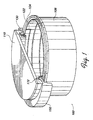
- Appareil pour introduire par couplage de l'énergie d'une source (108) dans un plasma, l'appareil comportant :une cible (110) ;un support (114) de substrat ;une zone de génération de plasma entre ladite cible (110) et ledit support (114) de substrat, etune première paroi conductrice (104) formant écran entourant la zone de génération de plasma et présentant une rainure (122) afin que ladite première paroi (104) formant écran comporte en outre plusieurs spires hélicoïdales espacées (123), dans lequel ladite rainure (122) occupe moins de 10 % de l'aire de surface de ladite première paroi conductrice (104) formant écran, lesdites premières spires hélicoïdales conductrices (123) formant écran étant couplées à ladite source (108) pour rayonner de l'énergie depuis lesdites premières spires hélicoïdales conductrices (123) formant écran vers l'intérieur de ladite zone de génération de plasma.
- Appareil selon la revendication 1, dans lequel ladite rainure (122) a une largeur inférieure à 1/4 inch (6,35 mm) afin que lesdites premières spires conductrices (123) formant écran soient espacées de moins de 1/4 inch (6,35 mm).
- Appareil selon la revendication 1 ou la revendication 2, dans lequel ladite première paroi conductrice (104) formant écran est de forme essentiellement cylindrique.
- Appareil selon la revendication 3, dans lequel ladite rainure (122) de ladite première paroi conductrice formant écran entoure ladite première paroi conductrice (104) formant écran plusieurs fois pour définir lesdites spires (123) de ladite première paroi conductrice formant écran.
- Appareil selon la revendication 3, dans lequel ladite rainure (122) de ladite première paroi conductrice formant écran est en forme d'hélice.
- Appareil selon la revendication 1, dans lequel ladite zone de génération de plasma a une face latérale et ladite première paroi (104) formant écran présente une aire de surface suffisante pour renfermer au moins 50 % de ladite face latérale de l'aire de génération de plasma.
- Appareil selon l'une quelconque des revendications précédentes, comportant en outre une seconde paroi (106) formant écran positionnée à l'extérieur de ladite première paroi conductrice (104) formant écran.
- Appareil selon la revendication 7, comportant en outre des pieds isolants (124) entre lesdites première (104) et seconde (106) parois formant écran.
- Appareil selon l'une quelconque des revendications précédentes, agencé pour introduire par couplage de l'énergie électromagnétique depuis une source RF dans le plasma, l'appareil comportant en outre :une chambre (100) ayant une paroi (107) de chambre ;dans lequel la première paroi conductrice (104) formant écran est positionnée à l'intérieur de la chambre (100) pour protéger au moins une partie de la paroi (107) de chambre de matières de dépôt, et dans lequel ladite paroi (104) formant écran comporte une bande continue de matière conductrice qui forme une bobine à spires multiples ayant deux extrémités, dont une extrémité est couplée à une première source RF et l'autre extrémité est couplée à la masse.
- Appareil selon la revendication 9 lorsqu'elle dépend de la revendication 7 ou de la revendication 8, dans lequel la seconde paroi (106) formant écran est positionnée entre ladite première paroi conductrice (104) formant écran et ladite paroi (107) de chambre de façon à protéger au moins une partie de la paroi (107) de chambre de matières de dépôt.
- Appareil selon la revendication 9 ou la revendication 10, dans lequel les premières spires conductrices (123) de la bobine formant écran sont couplées à ladite source RF (108) pour introduire par couplage inductif de l'énergie RF desdites premières spires conductrices (123) de la bobine formant écran dans ledit plasma de ladite zone de génération de plasma.
- Procédé de formation d'une antenne RF pour une chambre de dépôt sous plasma, comportant :l'usinage par coupe d'une rainure (122) dans une paroi (104) formant écran en matière conductrice afin que ladite paroi (104) formant écran forme une bobine à spires multiples, ladite rainure (122) occupant moins de 10 % de l'aire de la surface de la paroi conductrice (104) formant écran ;la mise en place de ladite paroi (104) formant écran entre une cible (110) et un support (114) de substrat ; etle couplage d'une source (108) d'énergie RF à ladite paroi (104) formant écran.
- Procédé selon la revendication 12, dans lequel ledit usinage par coupe est exécuté en utilisant un laser.
- Procédé selon la revendication 12, dans lequel ledit usinage par coupe est exécuté en utilisant un fil métallique chaud.
- Procédé selon la revendication 12, dans lequel ladite première paroi conductrice (104) formant écran est de forme essentiellement cylindrique.
- Procédé selon la revendication 15, dans lequel ladite rainure (122) entoure ladite première paroi conductrice (104) formant écran, plusieurs fois, pour définir lesdites premières spires conductrices (124) de paroi formant écran de ladite bobine.
- Procédé selon la revendication 12, dans lequel ladite rainure (122) est usinée par coupe en une forme en hélice.
- Procédé selon la revendication 12, dans lequel ladite rainure (122) a une largeur inférieure à 1/4 inch (6,35 mm).
- Procédé selon la revendication 12, comprenant en outre le blocage de la matière de dépôt en utilisant une seconde paroi (106) formant écran positionnée en arrière de ladite première paroi (104) formant écran.
- Procédé de dépôt par pulvérisation d'une matière de dépôt sur un substrat, comprenant :l'introduction par couplage d'énergie RF dans un plasma à partir d'une première paroi conductrice (104) formant écran, formée en une bobine ayant plusieurs spires (123), ladite première paroi conductrice (104) formant écran ayant une rainure (122) qui entoure ladite première paroi conductrice (104) formant écran plusieurs fois pour définir lesdites premières spires conductrices (123) de paroi formant écran de ladite bobine, et ladite rainure (122) occupant moins de 10 % de l'aire de la surface de ladite première paroi conductrice (104) formant écran ; etl'ionisation de la matière de dépôt passant à travers ledit plasma.
- Procédé selon la revendication 20, dans lequel ladite première paroi conductrice (104) formant écran est de forme essentiellement cylindrique.
- Procédé selon la revendication 20, dans lequel ladite rainure (122) est usinée par coupe en une forme en hélice.
- Procédé selon la revendication 20, dans lequel ladite rainure (122) a une largeur inférieure à 1/4 inch (6,35 mm).
- Procédé selon la revendication 20, comprenant en outre le blocage de la matière de dépôt en utilisant une seconde paroi (106) formant écran positionnée en arrière de ladite première paroi (104) formant écran.
Applications Claiming Priority (2)
| Application Number | Priority Date | Filing Date | Title |
|---|---|---|---|
| US08/730,722 US6254737B1 (en) | 1996-10-08 | 1996-10-08 | Active shield for generating a plasma for sputtering |
| US730722 | 1996-10-08 |
Publications (3)
| Publication Number | Publication Date |
|---|---|
| EP0836218A2 EP0836218A2 (fr) | 1998-04-15 |
| EP0836218A3 EP0836218A3 (fr) | 1998-09-16 |
| EP0836218B1 true EP0836218B1 (fr) | 2002-03-27 |
Family
ID=24936569
Family Applications (1)
| Application Number | Title | Priority Date | Filing Date |
|---|---|---|---|
| EP97307864A Expired - Lifetime EP0836218B1 (fr) | 1996-10-08 | 1997-10-06 | Ecran actif de génération d'un plasma pour la pulvérisation |
Country Status (6)
| Country | Link |
|---|---|
| US (1) | US6254737B1 (fr) |
| EP (1) | EP0836218B1 (fr) |
| JP (1) | JPH10183342A (fr) |
| KR (1) | KR19980032631A (fr) |
| DE (1) | DE69711314T2 (fr) |
| TW (1) | TW357387B (fr) |
Cited By (1)
| Publication number | Priority date | Publication date | Assignee | Title |
|---|---|---|---|---|
| US7094316B1 (en) | 2000-08-11 | 2006-08-22 | Applied Materials, Inc. | Externally excited torroidal plasma source |
Families Citing this family (67)
| Publication number | Priority date | Publication date | Assignee | Title |
|---|---|---|---|---|
| US5948215A (en) * | 1997-04-21 | 1999-09-07 | Tokyo Electron Limited | Method and apparatus for ionized sputtering |
| AU6977998A (en) * | 1997-04-21 | 1998-11-13 | Tokyo Electron Arizona, Inc. | Method and apparatus for ionized sputtering of materials |
| US6565717B1 (en) | 1997-09-15 | 2003-05-20 | Applied Materials, Inc. | Apparatus for sputtering ionized material in a medium to high density plasma |
| US6506287B1 (en) * | 1998-03-16 | 2003-01-14 | Applied Materials, Inc. | Overlap design of one-turn coil |
| USD440582S1 (en) | 1998-03-16 | 2001-04-17 | Applied Materials, Inc. | Sputtering chamber coil |
| US6287435B1 (en) | 1998-05-06 | 2001-09-11 | Tokyo Electron Limited | Method and apparatus for ionized physical vapor deposition |
| US6197165B1 (en) | 1998-05-06 | 2001-03-06 | Tokyo Electron Limited | Method and apparatus for ionized physical vapor deposition |
| US6080287A (en) * | 1998-05-06 | 2000-06-27 | Tokyo Electron Limited | Method and apparatus for ionized physical vapor deposition |
| JP3126698B2 (ja) | 1998-06-02 | 2001-01-22 | 富士通株式会社 | スパッタ成膜方法、スパッタ成膜装置及び半導体装置の製造方法 |
| US6660134B1 (en) * | 1998-07-10 | 2003-12-09 | Applied Materials, Inc. | Feedthrough overlap coil |
| USD450070S1 (en) | 1998-07-13 | 2001-11-06 | Applied Materials, Inc. | Sputtering chamber coil |
| US6248251B1 (en) | 1999-02-19 | 2001-06-19 | Tokyo Electron Limited | Apparatus and method for electrostatically shielding an inductively coupled RF plasma source and facilitating ignition of a plasma |
| US6237526B1 (en) | 1999-03-26 | 2001-05-29 | Tokyo Electron Limited | Process apparatus and method for improving plasma distribution and performance in an inductively coupled plasma |
| US6474258B2 (en) | 1999-03-26 | 2002-11-05 | Tokyo Electron Limited | Apparatus and method for improving plasma distribution and performance in an inductively coupled plasma |
| USD442852S1 (en) | 1999-08-24 | 2001-05-29 | Applied Materials, Inc. | Squared overlap coil |
| USD442853S1 (en) | 1999-08-24 | 2001-05-29 | Applied Materials, Inc. | Rounded overlap coil |
| US6679981B1 (en) * | 2000-05-11 | 2004-01-20 | Applied Materials, Inc. | Inductive plasma loop enhancing magnetron sputtering |
| US6418874B1 (en) | 2000-05-25 | 2002-07-16 | Applied Materials, Inc. | Toroidal plasma source for plasma processing |
| US7294563B2 (en) | 2000-08-10 | 2007-11-13 | Applied Materials, Inc. | Semiconductor on insulator vertical transistor fabrication and doping process |
| US6939434B2 (en) | 2000-08-11 | 2005-09-06 | Applied Materials, Inc. | Externally excited torroidal plasma source with magnetic control of ion distribution |
| US7223676B2 (en) | 2002-06-05 | 2007-05-29 | Applied Materials, Inc. | Very low temperature CVD process with independently variable conformality, stress and composition of the CVD layer |
| US6893907B2 (en) | 2002-06-05 | 2005-05-17 | Applied Materials, Inc. | Fabrication of silicon-on-insulator structure using plasma immersion ion implantation |
| US7166524B2 (en) | 2000-08-11 | 2007-01-23 | Applied Materials, Inc. | Method for ion implanting insulator material to reduce dielectric constant |
| US7137354B2 (en) | 2000-08-11 | 2006-11-21 | Applied Materials, Inc. | Plasma immersion ion implantation apparatus including a plasma source having low dissociation and low minimum plasma voltage |
| US7288491B2 (en) | 2000-08-11 | 2007-10-30 | Applied Materials, Inc. | Plasma immersion ion implantation process |
| US7037813B2 (en) | 2000-08-11 | 2006-05-02 | Applied Materials, Inc. | Plasma immersion ion implantation process using a capacitively coupled plasma source having low dissociation and low minimum plasma voltage |
| US6494986B1 (en) | 2000-08-11 | 2002-12-17 | Applied Materials, Inc. | Externally excited multiple torroidal plasma source |
| US6410449B1 (en) | 2000-08-11 | 2002-06-25 | Applied Materials, Inc. | Method of processing a workpiece using an externally excited torroidal plasma source |
| US7183177B2 (en) | 2000-08-11 | 2007-02-27 | Applied Materials, Inc. | Silicon-on-insulator wafer transfer method using surface activation plasma immersion ion implantation for wafer-to-wafer adhesion enhancement |
| US7430984B2 (en) | 2000-08-11 | 2008-10-07 | Applied Materials, Inc. | Method to drive spatially separate resonant structure with spatially distinct plasma secondaries using a single generator and switching elements |
| US7094670B2 (en) | 2000-08-11 | 2006-08-22 | Applied Materials, Inc. | Plasma immersion ion implantation process |
| US7465478B2 (en) | 2000-08-11 | 2008-12-16 | Applied Materials, Inc. | Plasma immersion ion implantation process |
| US7479456B2 (en) | 2004-08-26 | 2009-01-20 | Applied Materials, Inc. | Gasless high voltage high contact force wafer contact-cooling electrostatic chuck |
| US7303982B2 (en) | 2000-08-11 | 2007-12-04 | Applied Materials, Inc. | Plasma immersion ion implantation process using an inductively coupled plasma source having low dissociation and low minimum plasma voltage |
| US7320734B2 (en) | 2000-08-11 | 2008-01-22 | Applied Materials, Inc. | Plasma immersion ion implantation system including a plasma source having low dissociation and low minimum plasma voltage |
| US6453842B1 (en) | 2000-08-11 | 2002-09-24 | Applied Materials Inc. | Externally excited torroidal plasma source using a gas distribution plate |
| US6551446B1 (en) | 2000-08-11 | 2003-04-22 | Applied Materials Inc. | Externally excited torroidal plasma source with a gas distribution plate |
| US6468388B1 (en) | 2000-08-11 | 2002-10-22 | Applied Materials, Inc. | Reactor chamber for an externally excited torroidal plasma source with a gas distribution plate |
| US6634313B2 (en) | 2001-02-13 | 2003-10-21 | Applied Materials, Inc. | High-frequency electrostatically shielded toroidal plasma and radical source |
| US7513971B2 (en) * | 2002-03-18 | 2009-04-07 | Applied Materials, Inc. | Flat style coil for improved precision etch uniformity |
| US7244474B2 (en) | 2004-03-26 | 2007-07-17 | Applied Materials, Inc. | Chemical vapor deposition plasma process using an ion shower grid |
| US7695590B2 (en) | 2004-03-26 | 2010-04-13 | Applied Materials, Inc. | Chemical vapor deposition plasma reactor having plural ion shower grids |
| US7291360B2 (en) | 2004-03-26 | 2007-11-06 | Applied Materials, Inc. | Chemical vapor deposition plasma process using plural ion shower grids |
| US20050236270A1 (en) * | 2004-04-23 | 2005-10-27 | Heraeus, Inc. | Controlled cooling of sputter targets |
| US7767561B2 (en) | 2004-07-20 | 2010-08-03 | Applied Materials, Inc. | Plasma immersion ion implantation reactor having an ion shower grid |
| US8058156B2 (en) | 2004-07-20 | 2011-11-15 | Applied Materials, Inc. | Plasma immersion ion implantation reactor having multiple ion shower grids |
| US7666464B2 (en) | 2004-10-23 | 2010-02-23 | Applied Materials, Inc. | RF measurement feedback control and diagnostics for a plasma immersion ion implantation reactor |
| DE102005001651A1 (de) * | 2005-01-10 | 2006-07-20 | Infineon Technologies Ag | Ätzanlage |
| US9659758B2 (en) * | 2005-03-22 | 2017-05-23 | Honeywell International Inc. | Coils utilized in vapor deposition applications and methods of production |
| US7428915B2 (en) | 2005-04-26 | 2008-09-30 | Applied Materials, Inc. | O-ringless tandem throttle valve for a plasma reactor chamber |
| US7312162B2 (en) | 2005-05-17 | 2007-12-25 | Applied Materials, Inc. | Low temperature plasma deposition process for carbon layer deposition |
| US7109098B1 (en) | 2005-05-17 | 2006-09-19 | Applied Materials, Inc. | Semiconductor junction formation process including low temperature plasma deposition of an optical absorption layer and high speed optical annealing |
| US7422775B2 (en) | 2005-05-17 | 2008-09-09 | Applied Materials, Inc. | Process for low temperature plasma deposition of an optical absorption layer and high speed optical annealing |
| US20060278520A1 (en) * | 2005-06-13 | 2006-12-14 | Lee Eal H | Use of DC magnetron sputtering systems |
| US8617672B2 (en) | 2005-07-13 | 2013-12-31 | Applied Materials, Inc. | Localized surface annealing of components for substrate processing chambers |
| US7335611B2 (en) | 2005-08-08 | 2008-02-26 | Applied Materials, Inc. | Copper conductor annealing process employing high speed optical annealing with a low temperature-deposited optical absorber layer |
| US7429532B2 (en) | 2005-08-08 | 2008-09-30 | Applied Materials, Inc. | Semiconductor substrate process using an optically writable carbon-containing mask |
| US7312148B2 (en) | 2005-08-08 | 2007-12-25 | Applied Materials, Inc. | Copper barrier reflow process employing high speed optical annealing |
| US7323401B2 (en) | 2005-08-08 | 2008-01-29 | Applied Materials, Inc. | Semiconductor substrate process using a low temperature deposited carbon-containing hard mask |
| US7981262B2 (en) | 2007-01-29 | 2011-07-19 | Applied Materials, Inc. | Process kit for substrate processing chamber |
| US7942969B2 (en) | 2007-05-30 | 2011-05-17 | Applied Materials, Inc. | Substrate cleaning chamber and components |
| US8647485B2 (en) | 2012-03-30 | 2014-02-11 | Applied Materials, Inc. | Process kit shield for plasma enhanced processing chamber |
| US11183373B2 (en) | 2017-10-11 | 2021-11-23 | Honeywell International Inc. | Multi-patterned sputter traps and methods of making |
| JP7224621B2 (ja) * | 2018-10-19 | 2023-02-20 | サムコ株式会社 | 誘導結合型プラズマ処理装置の防着板 |
| US20220025519A1 (en) * | 2018-10-26 | 2022-01-27 | Lpe S.P.A. | Deposition reactor with inductors and electromagnetic shields |
| CN109837513A (zh) * | 2019-04-11 | 2019-06-04 | 德淮半导体有限公司 | 用于物理气相沉积设备的护罩结构及其物理气相沉积设备 |
| CN110004418A (zh) * | 2019-04-17 | 2019-07-12 | 德淮半导体有限公司 | 用于物理气相沉积设备的护罩结构以及物理气相沉积设备 |
Family Cites Families (77)
| Publication number | Priority date | Publication date | Assignee | Title |
|---|---|---|---|---|
| DE1765850A1 (de) | 1967-11-10 | 1971-10-28 | Euratom | Verfahren und Vorrichtung zum Aufbringen von duennen Schichten |
| DE1905058C3 (de) | 1969-02-01 | 1973-10-04 | Leybold-Heraeus Gmbh & Co, Kg, 5000 Koeln-Bayental | Vorrichtung für die Beschichtung von Werkstücken durch Hochfrequenz-Plasmazerstäubung von Werkstoffen im Vakuum |
| US3763031A (en) * | 1970-10-01 | 1973-10-02 | Cogar Corp | Rf sputtering apparatus |
| US4362632A (en) | 1974-08-02 | 1982-12-07 | Lfe Corporation | Gas discharge apparatus |
| JPS56500067A (fr) | 1978-12-29 | 1981-01-22 | ||
| US4277321A (en) | 1979-04-23 | 1981-07-07 | Bell Telephone Laboratories, Incorporated | Treating multilayer printed wiring boards |
| JPS567562A (en) | 1979-06-29 | 1981-01-26 | Canon Inc | Picture forming unit |
| US4336118A (en) | 1980-03-21 | 1982-06-22 | Battelle Memorial Institute | Methods for making deposited films with improved microstructures |
| JPS59190363A (ja) | 1983-04-11 | 1984-10-29 | Orient Watch Co Ltd | 金属薄膜の形成方法 |
| JPS6023929U (ja) | 1983-07-22 | 1985-02-19 | アルプス電気株式会社 | 磁気駆動装置 |
| US4661228A (en) | 1984-05-17 | 1987-04-28 | Varian Associates, Inc. | Apparatus and method for manufacturing planarized aluminum films |
| US4865712A (en) | 1984-05-17 | 1989-09-12 | Varian Associates, Inc. | Apparatus for manufacturing planarized aluminum films |
| EP0169744A3 (fr) | 1984-07-26 | 1987-06-10 | United Kingdom Atomic Energy Authority | Source d'ions |
| JPH0740468B2 (ja) | 1984-12-11 | 1995-05-01 | 株式会社日立製作所 | 高周波プラズマ発生装置 |
| JPS61190070A (ja) | 1985-02-20 | 1986-08-23 | Hitachi Ltd | スパツタ装置 |
| US4626312A (en) | 1985-06-24 | 1986-12-02 | The Perkin-Elmer Corporation | Plasma etching system for minimizing stray electrical discharges |
| GB8629634D0 (en) | 1986-12-11 | 1987-01-21 | Dobson C D | Reactive ion & sputter etching |
| US4792732A (en) | 1987-06-12 | 1988-12-20 | United States Of America As Represented By The Secretary Of The Air Force | Radio frequency plasma generator |
| US5175608A (en) | 1987-06-30 | 1992-12-29 | Hitachi, Ltd. | Method of and apparatus for sputtering, and integrated circuit device |
| JP2602276B2 (ja) | 1987-06-30 | 1997-04-23 | 株式会社日立製作所 | スパツタリング方法とその装置 |
| KR920003789B1 (ko) | 1988-02-08 | 1992-05-14 | 니뽄 덴신 덴와 가부시끼가이샤 | 플라즈마 스퍼터링을 이용한 박막 형성 장치 및 이온원 |
| US4842703A (en) | 1988-02-23 | 1989-06-27 | Eaton Corporation | Magnetron cathode and method for sputter coating |
| JP2859632B2 (ja) | 1988-04-14 | 1999-02-17 | キヤノン株式会社 | 成膜装置及び成膜方法 |
| US4871421A (en) | 1988-09-15 | 1989-10-03 | Lam Research Corporation | Split-phase driver for plasma etch system |
| US4925542A (en) | 1988-12-08 | 1990-05-15 | Trw Inc. | Plasma plating apparatus and method |
| US4918031A (en) | 1988-12-28 | 1990-04-17 | American Telephone And Telegraph Company,At&T Bell Laboratories | Processes depending on plasma generation using a helical resonator |
| GB8905075D0 (en) | 1989-03-06 | 1989-04-19 | Nordiko Ltd | Electrode assembly and apparatus |
| US5135629A (en) | 1989-06-12 | 1992-08-04 | Nippon Mining Co., Ltd. | Thin film deposition system |
| US5091049A (en) | 1989-06-13 | 1992-02-25 | Plasma & Materials Technologies, Inc. | High density plasma deposition and etching apparatus |
| US5429070A (en) | 1989-06-13 | 1995-07-04 | Plasma & Materials Technologies, Inc. | High density plasma deposition and etching apparatus |
| US4990229A (en) | 1989-06-13 | 1991-02-05 | Plasma & Materials Technologies, Inc. | High density plasma deposition and etching apparatus |
| US5122251A (en) | 1989-06-13 | 1992-06-16 | Plasma & Materials Technologies, Inc. | High density plasma deposition and etching apparatus |
| US5421891A (en) | 1989-06-13 | 1995-06-06 | Plasma & Materials Technologies, Inc. | High density plasma deposition and etching apparatus |
| US5234560A (en) | 1989-08-14 | 1993-08-10 | Hauzer Holdings Bv | Method and device for sputtering of films |
| US4948458A (en) | 1989-08-14 | 1990-08-14 | Lam Research Corporation | Method and apparatus for producing magnetically-coupled planar plasma |
| DE3942964A1 (de) | 1989-12-23 | 1991-06-27 | Leybold Ag | Einrichtung fuer die erzeugung eines plasmas |
| US5304279A (en) | 1990-08-10 | 1994-04-19 | International Business Machines Corporation | Radio frequency induction/multipole plasma processing tool |
| US5178739A (en) | 1990-10-31 | 1993-01-12 | International Business Machines Corporation | Apparatus for depositing material into high aspect ratio holes |
| WO1992007969A1 (fr) | 1990-10-31 | 1992-05-14 | International Business Machines Corporation | Appareil servant a deposer un materiau dans des trous dont le rapport d'elancement est eleve |
| US5206516A (en) | 1991-04-29 | 1993-04-27 | International Business Machines Corporation | Low energy, steered ion beam deposition system having high current at low pressure |
| JP2635267B2 (ja) | 1991-06-27 | 1997-07-30 | アプライド マテリアルズ インコーポレイテッド | Rfプラズマ処理装置 |
| US5234529A (en) | 1991-10-10 | 1993-08-10 | Johnson Wayne L | Plasma generating apparatus employing capacitive shielding and process for using such apparatus |
| US5280154A (en) | 1992-01-30 | 1994-01-18 | International Business Machines Corporation | Radio frequency induction plasma processing system utilizing a uniform field coil |
| US5368685A (en) | 1992-03-24 | 1994-11-29 | Hitachi, Ltd. | Dry etching apparatus and method |
| US5225740A (en) | 1992-03-26 | 1993-07-06 | General Atomics | Method and apparatus for producing high density plasma using whistler mode excitation |
| US5361016A (en) | 1992-03-26 | 1994-11-01 | General Atomics | High density plasma formation using whistler mode excitation in a reduced cross-sectional area formation tube |
| US5231334A (en) | 1992-04-15 | 1993-07-27 | Texas Instruments Incorporated | Plasma source and method of manufacturing |
| US5241245A (en) | 1992-05-06 | 1993-08-31 | International Business Machines Corporation | Optimized helical resonator for plasma processing |
| US5397962A (en) | 1992-06-29 | 1995-03-14 | Texas Instruments Incorporated | Source and method for generating high-density plasma with inductive power coupling |
| JP3688726B2 (ja) | 1992-07-17 | 2005-08-31 | 株式会社東芝 | 半導体装置の製造方法 |
| US5404079A (en) | 1992-08-13 | 1995-04-04 | Matsushita Electric Industrial Co., Ltd. | Plasma generating apparatus |
| US5312717A (en) | 1992-09-24 | 1994-05-17 | International Business Machines Corporation | Residue free vertical pattern transfer with top surface imaging resists |
| DE4235064A1 (de) | 1992-10-17 | 1994-04-21 | Leybold Ag | Vorrichtung zum Erzeugen eines Plasmas mittels Kathodenzerstäubung |
| US5346578A (en) | 1992-11-04 | 1994-09-13 | Novellus Systems, Inc. | Induction plasma source |
| US5433812A (en) | 1993-01-19 | 1995-07-18 | International Business Machines Corporation | Apparatus for enhanced inductive coupling to plasmas with reduced sputter contamination |
| US5366585A (en) | 1993-01-28 | 1994-11-22 | Applied Materials, Inc. | Method and apparatus for protection of conductive surfaces in a plasma processing reactor |
| JP3224443B2 (ja) | 1993-02-08 | 2001-10-29 | 靖浩 堀池 | ヘリコン波プラズマ処理装置 |
| JP3271359B2 (ja) | 1993-02-25 | 2002-04-02 | ソニー株式会社 | ドライエッチング方法 |
| US5401350A (en) | 1993-03-08 | 1995-03-28 | Lsi Logic Corporation | Coil configurations for improved uniformity in inductively coupled plasma systems |
| JP3252518B2 (ja) | 1993-03-19 | 2002-02-04 | ソニー株式会社 | ドライエッチング方法 |
| JP3174981B2 (ja) | 1993-03-26 | 2001-06-11 | 東京エレクトロン株式会社 | ヘリコン波プラズマ処理装置 |
| US5430355A (en) | 1993-07-30 | 1995-07-04 | Texas Instruments Incorporated | RF induction plasma source for plasma processing |
| US5418431A (en) | 1993-08-27 | 1995-05-23 | Hughes Aircraft Company | RF plasma source and antenna therefor |
| JP3290777B2 (ja) | 1993-09-10 | 2002-06-10 | 株式会社東芝 | 誘導結合型高周波放電方法および誘導結合型高周波放電装置 |
| US5431799A (en) * | 1993-10-29 | 1995-07-11 | Applied Materials, Inc. | Collimation hardware with RF bias rings to enhance sputter and/or substrate cavity ion generation efficiency |
| US5540824A (en) | 1994-07-18 | 1996-07-30 | Applied Materials | Plasma reactor with multi-section RF coil and isolated conducting lid |
| US5503676A (en) | 1994-09-19 | 1996-04-02 | Lam Research Corporation | Apparatus and method for magnetron in-situ cleaning of plasma reaction chamber |
| JPH07176399A (ja) | 1994-10-24 | 1995-07-14 | Tokyo Electron Ltd | プラズマ処理装置 |
| JP2657170B2 (ja) | 1994-10-24 | 1997-09-24 | 東京エレクトロン株式会社 | プラズマ処理装置 |
| US5569363A (en) | 1994-10-25 | 1996-10-29 | Sony Corporation | Inductively coupled plasma sputter chamber with conductive material sputtering capabilities |
| JP3483327B2 (ja) | 1994-11-29 | 2004-01-06 | アネルバ株式会社 | プラズマ処理方法 |
| JPH08288259A (ja) | 1995-04-18 | 1996-11-01 | Sony Corp | ヘリコン波プラズマ装置およびこれを用いたドライエッチング方法 |
| US5690795A (en) * | 1995-06-05 | 1997-11-25 | Applied Materials, Inc. | Screwless shield assembly for vacuum processing chambers |
| US5573595A (en) | 1995-09-29 | 1996-11-12 | Lam Research Corporation | Methods and apparatus for generating plasma |
| US6264812B1 (en) | 1995-11-15 | 2001-07-24 | Applied Materials, Inc. | Method and apparatus for generating a plasma |
| US5763851A (en) | 1995-11-27 | 1998-06-09 | Applied Materials, Inc. | Slotted RF coil shield for plasma deposition system |
| US5800688A (en) | 1997-04-21 | 1998-09-01 | Tokyo Electron Limited | Apparatus for ionized sputtering |
-
1996
- 1996-10-08 US US08/730,722 patent/US6254737B1/en not_active Expired - Fee Related
-
1997
- 1997-10-06 EP EP97307864A patent/EP0836218B1/fr not_active Expired - Lifetime
- 1997-10-06 DE DE69711314T patent/DE69711314T2/de not_active Expired - Fee Related
- 1997-10-07 TW TW086114655A patent/TW357387B/zh active
- 1997-10-08 KR KR1019970051488A patent/KR19980032631A/ko not_active Withdrawn
- 1997-10-08 JP JP9312570A patent/JPH10183342A/ja not_active Withdrawn
Cited By (1)
| Publication number | Priority date | Publication date | Assignee | Title |
|---|---|---|---|---|
| US7094316B1 (en) | 2000-08-11 | 2006-08-22 | Applied Materials, Inc. | Externally excited torroidal plasma source |
Also Published As
| Publication number | Publication date |
|---|---|
| TW357387B (en) | 1999-05-01 |
| JPH10183342A (ja) | 1998-07-14 |
| US6254737B1 (en) | 2001-07-03 |
| EP0836218A2 (fr) | 1998-04-15 |
| EP0836218A3 (fr) | 1998-09-16 |
| DE69711314D1 (de) | 2002-05-02 |
| DE69711314T2 (de) | 2002-11-14 |
| KR19980032631A (ko) | 1998-07-25 |
Similar Documents
| Publication | Publication Date | Title |
|---|---|---|
| EP0836218B1 (fr) | Ecran actif de génération d'un plasma pour la pulvérisation | |
| US6783639B2 (en) | Coils for generating a plasma and for sputtering | |
| US6190513B1 (en) | Darkspace shield for improved RF transmission in inductively coupled plasma sources for sputter deposition | |
| US6042700A (en) | Adjustment of deposition uniformity in an inductively coupled plasma source | |
| US6238528B1 (en) | Plasma density modulator for improved plasma density uniformity and thickness uniformity in an ionized metal plasma source | |
| US6132566A (en) | Apparatus and method for sputtering ionized material in a plasma | |
| US6254746B1 (en) | Recessed coil for generating a plasma | |
| US5961793A (en) | Method of reducing generation of particulate matter in a sputtering chamber | |
| US6660134B1 (en) | Feedthrough overlap coil | |
| US20130168232A1 (en) | Coils for generating a plasma and for sputtering | |
| US6506287B1 (en) | Overlap design of one-turn coil | |
| US6103070A (en) | Powered shield source for high density plasma | |
| US6231725B1 (en) | Apparatus for sputtering material onto a workpiece with the aid of a plasma | |
| EP0836219A2 (fr) | Ecran actif de génération d'un plasma pour la pulvérisation | |
| US6235169B1 (en) | Modulated power for ionized metal plasma deposition | |
| EP0841683A2 (fr) | Ecran actif de génération d'un plasma pour la pulvérisation | |
| US6409890B1 (en) | Method and apparatus for forming a uniform layer on a workpiece during sputtering |
Legal Events
| Date | Code | Title | Description |
|---|---|---|---|
| PUAI | Public reference made under article 153(3) epc to a published international application that has entered the european phase |
Free format text: ORIGINAL CODE: 0009012 |
|
| AK | Designated contracting states |
Kind code of ref document: A2 Designated state(s): BE CH DE FR GB IE IT LI NL |
|
| AX | Request for extension of the european patent |
Free format text: AL;LT;LV;RO;SI |
|
| PUAL | Search report despatched |
Free format text: ORIGINAL CODE: 0009013 |
|
| AK | Designated contracting states |
Kind code of ref document: A3 Designated state(s): AT BE CH DE DK ES FI FR GB GR IE IT LI LU MC NL PT SE |
|
| AX | Request for extension of the european patent |
Free format text: AL;LT;LV;RO;SI |
|
| 17P | Request for examination filed |
Effective date: 19990304 |
|
| AKX | Designation fees paid |
Free format text: BE CH DE FR GB IE IT LI NL |
|
| RBV | Designated contracting states (corrected) |
Designated state(s): BE CH DE FR GB IE IT LI NL |
|
| 17Q | First examination report despatched |
Effective date: 20001106 |
|
| GRAG | Despatch of communication of intention to grant |
Free format text: ORIGINAL CODE: EPIDOS AGRA |
|
| GRAG | Despatch of communication of intention to grant |
Free format text: ORIGINAL CODE: EPIDOS AGRA |
|
| GRAH | Despatch of communication of intention to grant a patent |
Free format text: ORIGINAL CODE: EPIDOS IGRA |
|
| GRAH | Despatch of communication of intention to grant a patent |
Free format text: ORIGINAL CODE: EPIDOS IGRA |
|
| REG | Reference to a national code |
Ref country code: GB Ref legal event code: IF02 |
|
| GRAA | (expected) grant |
Free format text: ORIGINAL CODE: 0009210 |
|
| AK | Designated contracting states |
Kind code of ref document: B1 Designated state(s): BE CH DE FR GB IE IT LI NL |
|
| PG25 | Lapsed in a contracting state [announced via postgrant information from national office to epo] |
Ref country code: NL Free format text: LAPSE BECAUSE OF FAILURE TO SUBMIT A TRANSLATION OF THE DESCRIPTION OR TO PAY THE FEE WITHIN THE PRESCRIBED TIME-LIMIT Effective date: 20020327 Ref country code: LI Free format text: LAPSE BECAUSE OF FAILURE TO SUBMIT A TRANSLATION OF THE DESCRIPTION OR TO PAY THE FEE WITHIN THE PRESCRIBED TIME-LIMIT Effective date: 20020327 Ref country code: IT Free format text: LAPSE BECAUSE OF FAILURE TO SUBMIT A TRANSLATION OF THE DESCRIPTION OR TO PAY THE FEE WITHIN THE PRESCRIBED TIME-LIMIT;WARNING: LAPSES OF ITALIAN PATENTS WITH EFFECTIVE DATE BEFORE 2007 MAY HAVE OCCURRED AT ANY TIME BEFORE 2007. THE CORRECT EFFECTIVE DATE MAY BE DIFFERENT FROM THE ONE RECORDED. Effective date: 20020327 Ref country code: FR Free format text: LAPSE BECAUSE OF FAILURE TO SUBMIT A TRANSLATION OF THE DESCRIPTION OR TO PAY THE FEE WITHIN THE PRESCRIBED TIME-LIMIT Effective date: 20020327 Ref country code: CH Free format text: LAPSE BECAUSE OF FAILURE TO SUBMIT A TRANSLATION OF THE DESCRIPTION OR TO PAY THE FEE WITHIN THE PRESCRIBED TIME-LIMIT Effective date: 20020327 Ref country code: BE Free format text: LAPSE BECAUSE OF FAILURE TO SUBMIT A TRANSLATION OF THE DESCRIPTION OR TO PAY THE FEE WITHIN THE PRESCRIBED TIME-LIMIT Effective date: 20020327 |
|
| REG | Reference to a national code |
Ref country code: CH Ref legal event code: EP |
|
| REF | Corresponds to: |
Ref document number: 69711314 Country of ref document: DE Date of ref document: 20020502 |
|
| REG | Reference to a national code |
Ref country code: IE Ref legal event code: FG4D |
|
| NLV1 | Nl: lapsed or annulled due to failure to fulfill the requirements of art. 29p and 29m of the patents act | ||
| PGFP | Annual fee paid to national office [announced via postgrant information from national office to epo] |
Ref country code: GB Payment date: 20020927 Year of fee payment: 6 |
|
| REG | Reference to a national code |
Ref country code: CH Ref legal event code: PL |
|
| PG25 | Lapsed in a contracting state [announced via postgrant information from national office to epo] |
Ref country code: IE Free format text: LAPSE BECAUSE OF NON-PAYMENT OF DUE FEES Effective date: 20021007 |
|
| EN | Fr: translation not filed | ||
| PLBE | No opposition filed within time limit |
Free format text: ORIGINAL CODE: 0009261 |
|
| STAA | Information on the status of an ep patent application or granted ep patent |
Free format text: STATUS: NO OPPOSITION FILED WITHIN TIME LIMIT |
|
| 26N | No opposition filed |
Effective date: 20021230 |
|
| REG | Reference to a national code |
Ref country code: IE Ref legal event code: MM4A |
|
| PG25 | Lapsed in a contracting state [announced via postgrant information from national office to epo] |
Ref country code: GB Free format text: LAPSE BECAUSE OF NON-PAYMENT OF DUE FEES Effective date: 20031006 |
|
| PGFP | Annual fee paid to national office [announced via postgrant information from national office to epo] |
Ref country code: DE Payment date: 20031031 Year of fee payment: 7 |
|
| GBPC | Gb: european patent ceased through non-payment of renewal fee |
Effective date: 20031006 |
|
| PG25 | Lapsed in a contracting state [announced via postgrant information from national office to epo] |
Ref country code: DE Free format text: LAPSE BECAUSE OF NON-PAYMENT OF DUE FEES Effective date: 20050503 |