EP0836220B1 - Lampe fluorescente a electrode externe et unite d'eclairage - Google Patents
Lampe fluorescente a electrode externe et unite d'eclairage Download PDFInfo
- Publication number
- EP0836220B1 EP0836220B1 EP97914599A EP97914599A EP0836220B1 EP 0836220 B1 EP0836220 B1 EP 0836220B1 EP 97914599 A EP97914599 A EP 97914599A EP 97914599 A EP97914599 A EP 97914599A EP 0836220 B1 EP0836220 B1 EP 0836220B1
- Authority
- EP
- European Patent Office
- Prior art keywords
- lamp
- electrodes
- fluorescent lamp
- external electrode
- light
- Prior art date
- Legal status (The legal status is an assumption and is not a legal conclusion. Google has not performed a legal analysis and makes no representation as to the accuracy of the status listed.)
- Expired - Lifetime
Links
Images







Classifications
-
- H—ELECTRICITY
- H01—ELECTRIC ELEMENTS
- H01J—ELECTRIC DISCHARGE TUBES OR DISCHARGE LAMPS
- H01J65/00—Lamps without any electrode inside the vessel; Lamps with at least one main electrode outside the vessel
-
- H—ELECTRICITY
- H01—ELECTRIC ELEMENTS
- H01J—ELECTRIC DISCHARGE TUBES OR DISCHARGE LAMPS
- H01J61/00—Gas-discharge or vapour-discharge lamps
- H01J61/02—Details
- H01J61/025—Associated optical elements
-
- H—ELECTRICITY
- H01—ELECTRIC ELEMENTS
- H01J—ELECTRIC DISCHARGE TUBES OR DISCHARGE LAMPS
- H01J61/00—Gas-discharge or vapour-discharge lamps
- H01J61/70—Lamps with low-pressure unconstricted discharge having a cold pressure < 400 Torr
-
- H—ELECTRICITY
- H01—ELECTRIC ELEMENTS
- H01J—ELECTRIC DISCHARGE TUBES OR DISCHARGE LAMPS
- H01J65/00—Lamps without any electrode inside the vessel; Lamps with at least one main electrode outside the vessel
- H01J65/04—Lamps in which a gas filling is excited to luminesce by an external electromagnetic field or by external corpuscular radiation, e.g. for indicating plasma display panels
- H01J65/042—Lamps in which a gas filling is excited to luminesce by an external electromagnetic field or by external corpuscular radiation, e.g. for indicating plasma display panels by an external electromagnetic field
- H01J65/046—Lamps in which a gas filling is excited to luminesce by an external electromagnetic field or by external corpuscular radiation, e.g. for indicating plasma display panels by an external electromagnetic field the field being produced by using capacitive means around the vessel
Definitions
- the invention relates to a fluorescent lamp of the external electrode type which is used for document scanning illumination which is used for an information processing device such as a fax machine, image reader and the like, and for a back light device of a liquid crystal display cell and for similar purposes.
- a fluorescent lamp which is used for a scanning light source of an office automation device and for back light of a liquid crystal display device and the like
- a fluorescent lamp of the external electrode type is known in which on the outside surface of a glass tube there is a pair of strip-like external electrodes to which a high frequency voltage is applied for operating.
- FIG. 7 is a schematic of one example of the fluorescent lamp of the external electrode type which is shown in a cross section perpendicular to the tube axis of the fluorescent lamp of the external electrode type.
- fluorescent lamp 10 of the external electrode type the outside of glass tube 1 is provided with a pair of strip-like external electrodes 2, 2'.
- Glass tube 1 is filled with a rare gas or the like.
- Fluorescent material 3 is applied to the inside of glass tube 1.
- An uninterrupted high frequency voltage or pulse-like high frequency voltage is applied to external electrodes 2, 2' to operate the lamp.
- fluorescent lamp 10 of the external electrode type a discharge is produced between external electrodes 2 and 2' by the high frequency voltage applied to the pair of external electrodes 2, 2' in the discharge space within glass tube 1.
- Fluorescent material 3 applied to the inside of glass tube 1 is caused to emit by the UV radiation which is formed by this discharge.
- the light formed by the discharge is radiated to the outside from aperture 4 and the side opposite it.
- the light emitted from aperture 4 is radiated onto the article to be irradiated.
- the light radiated to the outside from the side opposite aperture 4 is not effectively used.
- the intensity of the light with which the article to be irradiated is irradiated drops accordingly.
- the applicant has therefore proposed a technique for increasing the light intensity, in which reflector material is applied to the side opposite aperture 4 of fluorescent lamp 10 of the external electrode type (Japanese Patent Application HEI 7-313704).
- Figure 8 is a cross sectional view perpendicular to the tube axis of the fluorescent lamp of the external electrode type, in which the aforementioned reflector material is applied.
- the electrode width is labeled W.
- reflector material 6 is applied to the side opposite aperture 4, as is shown in Figure 8.
- emission by discharge the light emerging from aperture 4 of fluorescent lamp 10 of the external electrode type is increased by the light reflected by reflector material 6.
- emission by discharge can be effectively used without placing a reflector or the like outside of fluorescent lamp 10 of the external electrode type.
- the invention was devised to eliminate this disadvantage.
- the object of the invention was to devise a fluorescent lamp of the external electrode type in which the light intensity can be increased even more, and an irradiation unit using the fluorescent lamp.
- the light intensity of fluorescent lamp 10 of the external electrode type is increased by adding the light reflected by reflector material 6 to the emission light by discharge. This means that by effectively using the reflector material the light intensity of the fluorescent lamp of the external electrode type is increased.
- the electrode width W in Figure 8
- the emerging light emitted from the fluorescent lamp of the external electrode type is usually reduced.
- the emerging light emitted from the fluorescent lamp of the external electrode type is not greatly reduced with a suitable choice of the positions and the size of these slits, even if the electrode width (electrode area) becomes smaller according to the arrangement of the slits.
- the electrostatic capacity of the fluorescent lamp of the external electrode type diminishes.
- the power supplied to the fluorescent lamp of the external electrode type decreases accordingly.
- the electrode areas (regions in which the electrodes spread) including the slits do not change.
- the slits act almost like in a state in which the electrodes would be present in the slit areas. It can therefore be imagined that the electrostatic capacity of the fluorescent lamp of the external electrode type does not decrease significantly, and that as a result the emerging light emitted from the fluorescent lamp of the external electrode type hardly drops at all. In particular it has been found that the decrease of light intensity is less, the nearer the slots to the aperture arc located..
- the light intensity was studied by changing the type of reflector material. This showed that the increase of light intensity is not significantly dependent on the reflection factor or the reflector material and that the light intensity increases also in the case in which the reflection factor of the reflector material is smaller than the reflection factor of the electrode.
- Light intensity does decrease slightly by the arrangement of the translucent regions, like the slots or the like, in the electrodes.
- the light intensity of the fluorescent lamp of the external electrode type can be increased. It can be imagined that as a result the light intensity can be increased more strongly than in the fluorescent lamp of the external electrode type shown above in Figure 8, in which only the side opposite the aperture is provided with reflector material.
- the reflection factor of the reflector material need not always be higher than the reflection factor of the electrode. It was found that even in the case in which the reflection factor of the reflector material is lower than the reflection factor of the electrode, the light intensity of the fluorescent lamp of the external electrode type can be increased.
- the electrodes were provided with slits and the light intensity studied. However, it can be imagined that the same result can be obtained even if the electrodes are provided with openings instead of with slits.
- the intensity of the light emitted from the aperture is not decreased in the external electrodes by means of a suitable choice of the size and the positions and the like of these translucent regions, and even if the electrode areas decrease according to the arrangement of the translucent regions, then still another arrangement can be effected.
- the object as claimed in the invention is furthermore achieved by the electrodes being at least partially translucent, by a reflector device being located at a distance from the fluorescent lamp of the external electrode type, and by the light passed by the electrodes being at least partially reflected by this reflector device in the region which is irradiated with the radiant light from the aperture.
- Figure 1 is a schematic of one embodiment of the invention. It is a schematic cross section of the fluorescent lamp of the external electrode type, the cross section perpendicular to the tube axis.
- reference number 10 labels a fluorescent lamp of the external electrode type (hereinafter called simply a "lamp) with external electrodes 2,2' provided with slits as translucent regions S. Reflector material 6' is applied to these slits S.
- fluorescent material 3 is applied to the inside of glass tube 1 and the inside undergoes the stipulated evacuation and is then filled with rare gas which has xenon gas as the main component. The two ends of glass tube 1 are scaled. Fluorescent material 3 is removed from that inner side of the glass tube between external electrode 2 and 2' which forms aperture 4 and this region acts as effective emission surface 5.
- Electrodes 2, 2' which for example are formed from metal strips, such as Al, Cu and the like, or conductive enamel, such as silver paste and the like. Electrodes 2, 2' are provided with slits S. In these slits S and on the side opposite aperture 4 is reflector material 6, 6'. In the figure a case is shown in which slits S are located on the aperture sides of electrodes 2, 2' and in which reflector material 6' is located in these slits S. However slits S (and pertinent reflector material 6) can be located elsewhere on electrodes 2, 2', as was described below.
- Reflector material 6 was used which was produced by adding a binder to aluminum oxide and applying it to the outside of glass tube 1 in a thin layer and drying it. Besides aluminum oxide, barium sulfate, magnesium oxide, titanium oxide, calcium pyrophosphate or the like can be used as reflector material 6. Furthermore, without being limited to the material, reflector strips with a white color, silver color or the like which consist of a material with electrical insulation can be used. The electrical insulation of reflector material 6 has the effect to prevent creeping discharge of external electrodes 2,2' on the surface of glass tube 1.
- Figure 2 schematically shows the electrode widths of the lamps used in the experiment and the positions of slits S.
- Figure 2A shows aperture 4 at the top, electrodes using the thick lines and reflector material 6 using the broken line.
- the widths of electrodes 2, 2' and slit S are labelled a toc.
- Other components such as fluorescent material and the like are not shown.
- Figure 2 shows (1) a case in which electrode width is 8 mm, in which there is no slit and in which reflector material 6 is located on the side opposite aperture 4.
- Electrode width is 8 mm, and in which slits S of 2 mm are located in electrodes 2, 2' at sites which are 1 mm away from aperture 4. (Width of the remaining electrode parts is 5 mm, as is shown in Figure 2).
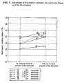
- Figure 3 is a schematic of the experiment result.
- the Y-axis is the illuminance (relative values in %) of the respective lamp, the illuminance of the lamp with an electrode width of 8 mm being designated 100.
- the x-axis represents the case of the arrangement of reflector material 6' in slits S of electrodes 2, 2' in the lamps with the respective electrode shape and the case of no reflector material.
- (1) through (5) correspond to (1) through (5) in Figure 2, as for example (1) shows the case of an electrode width of 8 mm and (2) the case of the electrode form of 1-2-5 mm.
- the illuminance for an electrode width of 8 mm is shown for comparison with the illuminance of the lamps in the embodiment as claimed in the invention.
- the value of the illuminance is shown in the case in which in both cases of “no reflector material in the electrode parts” and “reflector material in the electrode parts” on the side opposite aperture there is reflector material 6 (in the Figure the value of the illuminance for an electrode width of 8 mm in the case of "no reflector material in the electrode parts” is therefore identical to the value of the illuminance at an electrode width of 8 mm in the case of "reflector material in the electrode parts").
- the maximum illuminance can be obtained when in an electrode form with of 1-2-5 mm, reflector material 6' is located in the electrode parts. Furthermore in the case of an electrode form with of 5-2-1 mm essentially the same illuminance as the illuminance in the case of the electrode width of 8 mm can be obtained by reflector material 6' being located in the electrode parts.
- the illuminance decreases significantly compared to the case of the electrode width of 8 mm.
- the illuminance also decreases significantly in comparison to cases of an electrode form with of 1-2-5 mm, 3-2-3 mm and 5-2-1 mm.
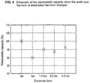
- FIG. 4 shows the electrostatic capacity.
- the electrostatic capacity (relative values in %) is shown in the case of an electrode with a width of 6 mm, in the case of an electrode with the form described above for (2) (1-2-5 mm), in the case with an electrode with the form described above for (3) (3-2-3 mm) and in the case of an electrode with the form described above for (4) (5-2-1 mm), the electrostatic capacity in the case of the arrangement of the electrode with a width of 8 mm being designated 100.
- the electrostatic capacity decreases when the electrode width is reduced from 8 to 6 mm.
- the electrostatic capacity does not decrease significantly, even if the electrode width decreases according to slits S (even if the electrode area is reduced).
- the slits act almost as in a state in which the electrodes would be present in the slit regions if there are slits S in the electrodes.
- the electrostatic capacity does not significantly decrease. Therefore almost the same effect can be obtained when cementing on the electrodes over a wide area.
- electrode can be provided with openings, as is shown in Figure 5B, or the entire electrode 2 can also be provided with openings with the same distances to one another, as is shown in Figure 5C.
- electrode 2 can be provided with openings such that the openings become larger, the nearer they are located to the light exit side (aperture), as is shown in Figure 5D.
- the electrode can be formed from a lattice. In the respective translucent region there can furthermore be reflector material 6'.
- the fluorescent material is applied on the inside of the glass tube which corresponds to the regions provided with reflector material 6,6'.
- the fluorescent material can also be removed in the regions which arc provided with reflector material 6,6'.
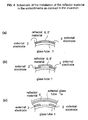
- reflector material 6,6' can be applied/cemented to the slit which is located in the electrode, in openings located in the electrode, and the like, as is illustrated for example in Figure 6(a), or can be cemented on the outside of the slotted region, the region of an opening and the like, as is illustrated in Figure 6(b). It can be imagined that in the two embodiments the same effect is achieved. Furthermore, reflector material 6 can be installed at a distance from external electrode 2, 2' and the light reflected by reflector material 6 can be guided back to the inside of the glass tube. Specifically, reflector material 6 as illustrated in Figure 6c can be located on the inside of outer glass tube 1a which is located at a stipulated distance from external electrodes 2.2'.
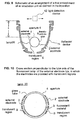
- Figure 9 is a schematic of the arrangement of a first embodiment of an irradiation unit as described in claim 3 of the invention.
- the drawing shows the arrangement of an irradiation unit which is used for back light device of a liquid crystal display cell.
- Figure 9 is a cross section perpendicular to the tube axis of a fluorescent lamp of the external electrode type of the irradiation device in this embodiment.
- Reference number 20 labels a fluorescent lamp of the external electrode type in which the external electrodes are provided with translucent regions
- reference number 11 labels a U-shaped reflector device for which aluminum was used, the inside of the U-shape having been subjected to mirror finishing.
- Figure 10 is a cross section perpendicular to the tube axis of a fluorescent lamp of the external electrode type (hereinafter called "lamp") in which the external electrodes arc provided with translucent regions S.
- the outside of glass tube 1 is provided with a pair of strip-like external electrodes 2, 2' which have translucent regions S such as openings, slits or the like.
- Glass tube 1 is filled with rare gas or the like, and on the inside of glass tubc 1 fluorescent material 3 is applied.
- the lamp is operated like the lamp described above using Figure 8 by applying an uninterrupted high frequency voltage or pulse-like high frequency voltage to external electrode 2, 2'.
- the lamp described above using Figure 5 can be used for lamp 20.
- the light emitted from translucent regions S is reflected by reflector device 11, emitted from the opening of the U-shaped reflector device, and used. Therefore the light intensity can be increased compared to the conventional case of using a lamp which is not provided with translucent regions S.
- a pulse-like voltage of 1600 V and 75 kHz was applied to the lamp for operation.
- the input voltage of a transformer which was used to generate the pulse-like voltage was 24 V and the input current thereof was 0.6 A.
- Figure 11 schematically shows the measurement result.
- the thick line shows the distribution of the illuminance in the case of using a lamp with translucent regions
- the thin line shows the distribution of illuminance in the case of using a lamp without translucent regions.
- the X-axis shows the position of light detection device 12 shown in Figure 9 (the center of the optical axis as 0 mm) and the Y-axis shows the intensity of the light received by light detection device 12.
- the intensity of the light emitted from the irradiation unit in the case of using the lamp with the translucent regions is increased more strongly than in the case of using the lamp without translucent regions. This confirms the action in this embodiment.
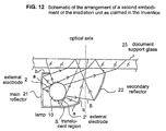
- Figure 12 is a schematic of the arrangement of a second embodiment of the irradiation unit.
- the arrangement of an irradiation unit is shown which is used for document scanning illumination of an information processing device.
- Figure 12 is a cross section perpendicular to the tube axis of the lamp of the irradiation unit.
- reference number 10 labels a lamp in which the external electrodes are provided with translucent regions, reference number 21 a main reflector, reference number 22 a secondary reflector, reference number 23 a document support glass on which the document to be scanned is placed.
- Main reflector 21 is arranged such that it surrounds lamp.
- regions a are made roughly oval or in the form of a circular curve in order to be able to focus the light.
- ends b of main reflector 21 arc bent so that the light emitted from lamp 10 is not directly incident on an image pick-up clement which is not shown in the drawing.
- Secondary reflector 22 is made roughly oval or in the form of a circular curve and focusses the light emitted from lamp 10.
- the light emitted from aperture and translucent regions S of lamp 10 is radiated directly onto document support glass 23.
- the light is simultaneously reflected by main reflector 21 and secondary reflector 22 and radiated onto document support glass 23.
- This light is reflected from the surface of the document placed on the document support glass and is incident via slit S located between main reflector 21 and secondary reflector 22 and via an optical system from a mirror, a lens and the like on an image pick-up element (not shown in the drawing) such as a CCD or the like.
- the light emitted from aperture 4 and translucent regions S of lamp 10 is radiated onto the document surface on document support glass 23 after reflection from main reflector 21 and secondary reflector 22. Therefore, as in the first embodiment, the amount of light emerging compared to the case of using the lamp which is not provided with translucent regions S can be increased.
- Figure 13 schematically shows the measurement result.
- the thick line shows the distribution of illuminance in the case of using a lamp with translucent regions
- the solid line shows the distribution of illuminance in the case of using a lamp without translucent regions.
- the x-axis shows the distance from the optical axis in the direction which orthogonally intersects the lamp tube axis on the document support glass and the y-axis shows the light intensity at the respective point.
- the direction of the "lamp side" arrow represents the side on which lamp 10 is located in Figure 12.
- the intensity of the light emitted from the irradiation unit in the case of using a lamp with translucent regions is increased more strongly than in the case of using the lamp without the translucent regions. In this way the action in this embodiment is confirmed.
- the light intensity distribution was measured in a conventionally used irradiation unit for document scanning illumination and in the irradiation unit in this embodiment, the action of the irradiation unit having been confirmed in this embodiment.
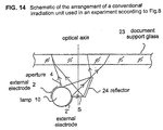
- Figure 14 is a schematic of the arrangement of the conventional irradiation unit for document scanning illumination which was used in the comparison experiment.
- reference number 10 labels the lamp shown above using Figure 7, in which the external electrodes arc not provided with translucent regions, reference number 23 labels a document support glass, and reference number 24 a reflector.
- the light is emitted from the aperture of lamp 10 without translucent regions and is radiated directly onto the document surface on the document support glass. At the same time it is reflected from reflector 24 and radiated onto the surface of the document which is placed on document support glass 23. The light reflected thereby is incident via slit S located between lamp 10 and reflector 24 and via an optical system and a lens which are not shown onto an image scanning means such as a CCD or the like.
- a lamp with a length of 370 mm and a tube diameter of 8 mm was used, as was described above.
- the lamp was operated under the same operating conditions as in the above described example, a light detection device having been moved on the document surface and the light intensity distribution having been measured.
- Figure 15 schematically shows the result of the experiment. On the left the distribution of the illuminance of the irradiation unit in Figure 14 is shown and on the right the distribution of the illuminance of the irradiation unit in Figure 12 for this embodiment is shown.
- the x-axis shows the distance from the optical axis in the direction which orthogonally intersects the lamp tube axis on the document support glass and the y-axis plots the illuminance at the respective point (relative values, the peak illuminance of the conventional irradiation unit being designated as 100 in Figure 7).
- the direction of the "lamp sidc" arrow represents the side on which the lamp in Figures 12 and 14 is located.
- the fluorescent lamp of the external electrode type as claimed in the invention and the irradiation unit using this fluorescent lamp can be used for document scanning illumination which is used for a fax machine, a copier, a image reader and the like, and for a back light device of a liquid crystal display cell and for similar purposes.
Landscapes
- Physics & Mathematics (AREA)
- Engineering & Computer Science (AREA)
- Plasma & Fusion (AREA)
- Electromagnetism (AREA)
- Vessels And Coating Films For Discharge Lamps (AREA)
Claims (3)
- Lampe fluorescente du type à électrode externe, dans laquelle un tube de verre (1), sur l'intérieur duquel est appliqué un matériau fluorescent (3), est hermétiquement rempli avec une quantité appropriée de gaz rare, dans laquelle, dans la direction axiale de la surface extérieure du tube de verre, se trouve au moins une paire d'électrodes (2, 2'), et dans laquelle se trouve une ouverture (4) pour une émission de lumière vers l'extérieur, caractérisée en ce que les électrodes (2, 2') sont, au moins partiellement, translucides, et un matériau réflecteur (6') est situé dans ces zones translucides (5).
- Lampe fluorescente du type à électrode externe selon la Revendication 1, dans laquelle les zones translucides sont situées au voisinage de l'ouverture (4).
- Unité d'irradiation utilisant une lampe fluorescente (20) du type à électrode externe, dans la lampe fluorescente (20) du type à électrode externe, un tube de verre (1) sur l'intérieur duquel est appliqué un matériau fluorescent (3) étant hermétiquement rempli avec une quantité appropriée de gaz rare, dans la direction axiale de la surface extérieure du tube de verre se trouvant au moins une paire d'électrodes (2, 2'), et se trouvant une ouverture (4) pour une émission de lumière vers l'extérieur, caractérisée en ce que les électrodes (2, 2') sont, au moins partiellement, translucides, en ce qu 'un dispositif réflecteur (11) est situé à une certaine distance de la lampe fluorescente du type à électrode externe, et dans laquelle la lumière envoyée par les électrodes (2,2') est, au moins partiellement, réfléchie par ce dispositif réflecteur (11) dans la zone qui est irradiée avec la lumière rayonnante venant de l'ouverture (4).
Applications Claiming Priority (7)
| Application Number | Priority Date | Filing Date | Title |
|---|---|---|---|
| JP109109/96 | 1996-04-30 | ||
| JP08109109A JP3109435B2 (ja) | 1996-04-30 | 1996-04-30 | 外部電極型蛍光ランプ |
| JP10910996 | 1996-04-30 | ||
| JP8144121A JPH09325707A (ja) | 1996-06-06 | 1996-06-06 | 外部電極型蛍光ランプを用いた照射ユニット |
| JP14412196 | 1996-06-06 | ||
| JP144121/96 | 1996-06-06 | ||
| PCT/JP1997/001160 WO1997041589A1 (fr) | 1996-04-30 | 1997-04-04 | Lampe fluorescente a electrode externe et unite d'eclairage |
Publications (3)
| Publication Number | Publication Date |
|---|---|
| EP0836220A1 EP0836220A1 (fr) | 1998-04-15 |
| EP0836220A4 EP0836220A4 (fr) | 1998-08-26 |
| EP0836220B1 true EP0836220B1 (fr) | 2002-07-17 |
Family
ID=26448891
Family Applications (1)
| Application Number | Title | Priority Date | Filing Date |
|---|---|---|---|
| EP97914599A Expired - Lifetime EP0836220B1 (fr) | 1996-04-30 | 1997-04-04 | Lampe fluorescente a electrode externe et unite d'eclairage |
Country Status (8)
| Country | Link |
|---|---|
| US (1) | US5889366A (fr) |
| EP (1) | EP0836220B1 (fr) |
| KR (1) | KR100405264B1 (fr) |
| CN (1) | CN1106680C (fr) |
| CA (1) | CA2225832C (fr) |
| DE (1) | DE69713980T2 (fr) |
| TW (1) | TW324054B (fr) |
| WO (1) | WO1997041589A1 (fr) |
Families Citing this family (27)
| Publication number | Priority date | Publication date | Assignee | Title |
|---|---|---|---|---|
| DE19817475B4 (de) * | 1998-04-20 | 2004-04-15 | Patent-Treuhand-Gesellschaft für elektrische Glühlampen mbH | Entladungslampe mit dielektrisch behinderten Elektroden sowie Beleuchtungssystem mit einer solchen Entladungslampe |
| DE19844921A1 (de) * | 1998-09-30 | 2000-04-13 | Patent Treuhand Ges Fuer Elektrische Gluehlampen Mbh | Flache Beleuchtungsvorrichtung |
| EP1111656A4 (fr) * | 1999-06-07 | 2007-03-28 | Toshiba Lighting & Technology | Tube a decharge, dispositif a tube a decharge et lecteur d'images |
| KR200179707Y1 (ko) | 1999-12-10 | 2000-04-15 | 김정규 | 자물쇠의 구조 |
| JP3604606B2 (ja) | 2000-01-07 | 2004-12-22 | コニカミノルタビジネステクノロジーズ株式会社 | 発光制御装置とこの発光制御装置を使用した画像形成装置 |
| JP4322409B2 (ja) * | 2000-07-14 | 2009-09-02 | Nec液晶テクノロジー株式会社 | アパーチャ型蛍光ランプの製造方法、面照明装置の製造方法、液晶表示装置、及び電子機器 |
| DE10048409A1 (de) * | 2000-09-29 | 2002-04-11 | Patent Treuhand Ges Fuer Elektrische Gluehlampen Mbh | Entladungslampe mit kapazitiver Feldmodulation |
| JP3929265B2 (ja) * | 2001-07-31 | 2007-06-13 | 富士通株式会社 | ガス放電管内への電子放出膜形成方法 |
| KR100840932B1 (ko) * | 2002-03-22 | 2008-06-24 | 삼성전자주식회사 | 램프, 이의 제조 방법 및 이를 이용한 액정표시장치 |
| KR100857990B1 (ko) * | 2002-08-05 | 2008-09-10 | 비오이 하이디스 테크놀로지 주식회사 | 액정표시장치의 백라이트유니트 구조 |
| KR100493386B1 (ko) | 2002-12-18 | 2005-06-07 | 엘지.필립스 엘시디 주식회사 | 백 라이트 유닛 |
| KR100525440B1 (ko) * | 2002-12-31 | 2005-11-02 | 엘지.필립스 엘시디 주식회사 | 백 라이트 유닛 |
| DE10336088A1 (de) * | 2003-08-06 | 2005-03-03 | Patent-Treuhand-Gesellschaft für elektrische Glühlampen mbH | UV-Strahler mit rohrförmigem Entladungsgefäß |
| US6971766B2 (en) * | 2003-10-31 | 2005-12-06 | Honeywell International Inc. | Redundant aperture lamp system |
| JP2005347569A (ja) * | 2004-06-03 | 2005-12-15 | Ushio Inc | フラッシュランプ照射装置 |
| KR101114853B1 (ko) * | 2004-12-13 | 2012-03-07 | 엘지디스플레이 주식회사 | 액정표시장치용 외부전극형광램프 및 그의 제조방법 |
| KR101127823B1 (ko) * | 2004-12-27 | 2012-03-26 | 엘지디스플레이 주식회사 | 백라이트 어셈블리 |
| JP4400469B2 (ja) * | 2005-02-02 | 2010-01-20 | ウシオ電機株式会社 | 希ガス蛍光ランプ |
| KR101150200B1 (ko) * | 2005-06-24 | 2012-06-12 | 엘지디스플레이 주식회사 | 표면에 프리즘 패턴을 가지는 형광램프 및 이를 이용하는액정표시장치 모듈 |
| TWI366858B (en) * | 2005-07-29 | 2012-06-21 | Gs Yuasa Int Ltd | Ultraviolet lamp and ultraviolet irradiating device |
| US7547112B2 (en) * | 2005-12-12 | 2009-06-16 | Led Folio Corporation | Low-clearance light emitting diode lighting |
| KR101183418B1 (ko) * | 2005-12-30 | 2012-09-14 | 엘지디스플레이 주식회사 | 외부 전극 형광램프 및 이를 이용한 액정표시장치의백라이트 유닛 |
| CN101473412A (zh) * | 2006-05-24 | 2009-07-01 | E.I.内穆尔杜邦公司 | 形成外部电极荧光灯的方法,其中使用的厚膜电极组合物以及由其形成的灯和lcd器件 |
| US7370986B2 (en) * | 2006-07-19 | 2008-05-13 | Gaya Co., Ltd. | Lamp body for a fluorescent lamp |
| JP4241835B2 (ja) * | 2007-01-12 | 2009-03-18 | ウシオ電機株式会社 | 放電ランプ |
| FR2915314B1 (fr) * | 2007-04-17 | 2011-04-22 | Saint Gobain | Lampe plane uv a decharges et utilisations. |
| US11682547B1 (en) * | 2022-02-10 | 2023-06-20 | Langsim Optoelectronic Technologies (Guangdong) Limited | Ultraviolet lamp tube and gas discharge UV lamp |
Family Cites Families (7)
| Publication number | Priority date | Publication date | Assignee | Title |
|---|---|---|---|---|
| SU762059A1 (ru) * | 1978-11-09 | 1980-09-07 | Viktor Eremin | Электроннолучевой импульсный источник оптического излучения 1 |
| CH675178A5 (fr) * | 1987-10-23 | 1990-08-31 | Bbc Brown Boveri & Cie | |
| EP0521553B1 (fr) * | 1991-07-01 | 1996-04-24 | Koninklijke Philips Electronics N.V. | Lampe à décharge luminescente à haute pression |
| JPH05242870A (ja) * | 1992-02-28 | 1993-09-21 | Mitsubishi Electric Corp | 放電ランプ |
| JP2747975B2 (ja) * | 1994-05-27 | 1998-05-06 | 株式会社藤商事 | 遊技機枠の成形方法 |
| JPH0992227A (ja) * | 1995-09-25 | 1997-04-04 | Toshiba Lighting & Technol Corp | 蛍光ランプおよび照明装置 |
| JP3171077B2 (ja) * | 1995-11-08 | 2001-05-28 | ウシオ電機株式会社 | 外部電極式蛍光放電管 |
-
1997
- 1997-04-04 CN CN97190449A patent/CN1106680C/zh not_active Expired - Fee Related
- 1997-04-04 KR KR1019970709961A patent/KR100405264B1/ko not_active Expired - Fee Related
- 1997-04-04 CA CA002225832A patent/CA2225832C/fr not_active Expired - Fee Related
- 1997-04-04 WO PCT/JP1997/001160 patent/WO1997041589A1/fr not_active Ceased
- 1997-04-04 US US08/981,008 patent/US5889366A/en not_active Expired - Lifetime
- 1997-04-04 EP EP97914599A patent/EP0836220B1/fr not_active Expired - Lifetime
- 1997-04-04 DE DE69713980T patent/DE69713980T2/de not_active Expired - Lifetime
- 1997-04-08 TW TW086104466A patent/TW324054B/zh not_active IP Right Cessation
Also Published As
| Publication number | Publication date |
|---|---|
| EP0836220A1 (fr) | 1998-04-15 |
| CA2225832A1 (fr) | 1997-11-06 |
| KR19990028639A (ko) | 1999-04-15 |
| EP0836220A4 (fr) | 1998-08-26 |
| CA2225832C (fr) | 2002-01-08 |
| DE69713980T2 (de) | 2003-03-20 |
| WO1997041589A1 (fr) | 1997-11-06 |
| US5889366A (en) | 1999-03-30 |
| KR100405264B1 (ko) | 2004-03-24 |
| CN1106680C (zh) | 2003-04-23 |
| TW324054B (en) | 1998-01-01 |
| DE69713980D1 (de) | 2002-08-22 |
| CN1189916A (zh) | 1998-08-05 |
Similar Documents
| Publication | Publication Date | Title |
|---|---|---|
| US5889366A (en) | Fluorescent lamp of the external electrode type and irradiation unit | |
| US5034655A (en) | Circular fluorescent lamp | |
| JP3184404B2 (ja) | 反射鏡付きメタルハライドランプ | |
| EP0817542A1 (fr) | Dispositif d'eclairage de lampe a decharge | |
| KR100372959B1 (ko) | 투영용금속할로겐화물가스방전램프 | |
| CN100358085C (zh) | 反射器灯 | |
| JP2001243921A (ja) | 希ガス放電ランプおよび照明装置 | |
| KR20040021570A (ko) | 점화 장치를 갖는 방전 램프 | |
| JP3509551B2 (ja) | 外部電極型放電ランプによる光源装置 | |
| JP2729994B2 (ja) | 蛍光ランプ | |
| JP3576661B2 (ja) | 希ガス放電灯 | |
| JP3235357B2 (ja) | 反射鏡付管球 | |
| JPH11283579A (ja) | 内外電極形蛍光ランプおよび照明装置 | |
| JP3109435B2 (ja) | 外部電極型蛍光ランプ | |
| EP0031175A1 (fr) | Lampe à décharge dans la vapeur de mercure à basse pression | |
| JP3424624B2 (ja) | 希ガス蛍光灯 | |
| JP3346275B2 (ja) | 外部電極形蛍光ランプ | |
| JP2729995B2 (ja) | 蛍光ランプ | |
| JPH06314561A (ja) | 放電ランプ | |
| JP2001155685A (ja) | 放電ランプ | |
| JP4641883B2 (ja) | 原稿照明装置、および画像読取装置 | |
| JP3346290B2 (ja) | 外部電極型蛍光ランプ | |
| JP3171077B2 (ja) | 外部電極式蛍光放電管 | |
| JP2003223870A (ja) | 光源装置および画像読みとり装置 | |
| JPH09325707A (ja) | 外部電極型蛍光ランプを用いた照射ユニット |
Legal Events
| Date | Code | Title | Description |
|---|---|---|---|
| PUAI | Public reference made under article 153(3) epc to a published international application that has entered the european phase |
Free format text: ORIGINAL CODE: 0009012 |
|
| AK | Designated contracting states |
Kind code of ref document: A1 Designated state(s): DE FR GB NL |
|
| 17P | Request for examination filed |
Effective date: 19980326 |
|
| A4 | Supplementary search report drawn up and despatched | ||
| AK | Designated contracting states |
Kind code of ref document: A4 Designated state(s): DE FR GB NL |
|
| GRAG | Despatch of communication of intention to grant |
Free format text: ORIGINAL CODE: EPIDOS AGRA |
|
| GRAG | Despatch of communication of intention to grant |
Free format text: ORIGINAL CODE: EPIDOS AGRA |
|
| GRAH | Despatch of communication of intention to grant a patent |
Free format text: ORIGINAL CODE: EPIDOS IGRA |
|
| 17Q | First examination report despatched |
Effective date: 20011207 |
|
| GRAH | Despatch of communication of intention to grant a patent |
Free format text: ORIGINAL CODE: EPIDOS IGRA |
|
| GRAA | (expected) grant |
Free format text: ORIGINAL CODE: 0009210 |
|
| AK | Designated contracting states |
Kind code of ref document: B1 Designated state(s): DE FR GB NL |
|
| REG | Reference to a national code |
Ref country code: GB Ref legal event code: FG4D |
|
| REF | Corresponds to: |
Ref document number: 69713980 Country of ref document: DE Date of ref document: 20020822 |
|
| ET | Fr: translation filed | ||
| PLBE | No opposition filed within time limit |
Free format text: ORIGINAL CODE: 0009261 |
|
| STAA | Information on the status of an ep patent application or granted ep patent |
Free format text: STATUS: NO OPPOSITION FILED WITHIN TIME LIMIT |
|
| 26N | No opposition filed |
Effective date: 20030422 |
|
| REG | Reference to a national code |
Ref country code: FR Ref legal event code: PLFP Year of fee payment: 19 |
|
| PGFP | Annual fee paid to national office [announced via postgrant information from national office to epo] |
Ref country code: NL Payment date: 20150309 Year of fee payment: 19 |
|
| PGFP | Annual fee paid to national office [announced via postgrant information from national office to epo] |
Ref country code: DE Payment date: 20150331 Year of fee payment: 19 Ref country code: GB Payment date: 20150401 Year of fee payment: 19 |
|
| PGFP | Annual fee paid to national office [announced via postgrant information from national office to epo] |
Ref country code: FR Payment date: 20150408 Year of fee payment: 19 |
|
| REG | Reference to a national code |
Ref country code: DE Ref legal event code: R119 Ref document number: 69713980 Country of ref document: DE |
|
| REG | Reference to a national code |
Ref country code: NL Ref legal event code: MM Effective date: 20160501 |
|
| GBPC | Gb: european patent ceased through non-payment of renewal fee |
Effective date: 20160404 |
|
| REG | Reference to a national code |
Ref country code: FR Ref legal event code: ST Effective date: 20161230 |
|
| PG25 | Lapsed in a contracting state [announced via postgrant information from national office to epo] |
Ref country code: GB Free format text: LAPSE BECAUSE OF NON-PAYMENT OF DUE FEES Effective date: 20160404 Ref country code: FR Free format text: LAPSE BECAUSE OF NON-PAYMENT OF DUE FEES Effective date: 20160502 Ref country code: DE Free format text: LAPSE BECAUSE OF NON-PAYMENT OF DUE FEES Effective date: 20161101 Ref country code: NL Free format text: LAPSE BECAUSE OF NON-PAYMENT OF DUE FEES Effective date: 20160501 |