EP0836668B2 - Multioperationsverfahren für die ausführung von explorations- und/oder entwicklungsbohrungen im offshore-bereich - Google Patents
Multioperationsverfahren für die ausführung von explorations- und/oder entwicklungsbohrungen im offshore-bereich Download PDFInfo
- Publication number
- EP0836668B2 EP0836668B2 EP97903797A EP97903797A EP0836668B2 EP 0836668 B2 EP0836668 B2 EP 0836668B2 EP 97903797 A EP97903797 A EP 97903797A EP 97903797 A EP97903797 A EP 97903797A EP 0836668 B2 EP0836668 B2 EP 0836668B2
- Authority
- EP
- European Patent Office
- Prior art keywords
- drilling
- advancing
- tubular
- water
- tubular members
- Prior art date
- Legal status (The legal status is an assumption and is not a legal conclusion. Google has not performed a legal analysis and makes no representation as to the accuracy of the status listed.)
- Expired - Lifetime
Links
- 238000005553 drilling Methods 0.000 title claims description 136
- 230000000694 effects Effects 0.000 title claims description 66
- 238000000034 method Methods 0.000 title claims description 36
- 238000011161 development Methods 0.000 title description 10
- XLYOFNOQVPJJNP-UHFFFAOYSA-N water Substances O XLYOFNOQVPJJNP-UHFFFAOYSA-N 0.000 claims description 45
- PEDCQBHIVMGVHV-UHFFFAOYSA-N Glycerine Chemical compound OCC(O)CO PEDCQBHIVMGVHV-UHFFFAOYSA-N 0.000 description 18
- 230000000712 assembly Effects 0.000 description 15
- 238000000429 assembly Methods 0.000 description 15
- 238000012360 testing method Methods 0.000 description 11
- 239000004568 cement Substances 0.000 description 10
- 238000003860 storage Methods 0.000 description 9
- XEEYBQQBJWHFJM-UHFFFAOYSA-N Iron Chemical compound [Fe] XEEYBQQBJWHFJM-UHFFFAOYSA-N 0.000 description 8
- 238000013461 design Methods 0.000 description 6
- 230000009977 dual effect Effects 0.000 description 5
- 229910052742 iron Inorganic materials 0.000 description 4
- 238000002360 preparation method Methods 0.000 description 3
- 238000012546 transfer Methods 0.000 description 3
- 238000004378 air conditioning Methods 0.000 description 2
- 230000005484 gravity Effects 0.000 description 2
- 238000004519 manufacturing process Methods 0.000 description 2
- 230000000246 remedial effect Effects 0.000 description 2
- 230000003466 anti-cipated effect Effects 0.000 description 1
- 238000010835 comparative analysis Methods 0.000 description 1
- 230000007613 environmental effect Effects 0.000 description 1
- 239000002828 fuel tank Substances 0.000 description 1
- 238000003384 imaging method Methods 0.000 description 1
- 238000005259 measurement Methods 0.000 description 1
- 230000002265 prevention Effects 0.000 description 1
- 239000007787 solid Substances 0.000 description 1
- 238000009987 spinning Methods 0.000 description 1
- 210000003462 vein Anatomy 0.000 description 1
- 238000003466 welding Methods 0.000 description 1
Images


Classifications
-
- E—FIXED CONSTRUCTIONS
- E21—EARTH OR ROCK DRILLING; MINING
- E21B—EARTH OR ROCK DRILLING; OBTAINING OIL, GAS, WATER, SOLUBLE OR MELTABLE MATERIALS OR A SLURRY OF MINERALS FROM WELLS
- E21B15/00—Supports for the drilling machine, e.g. derricks or masts
- E21B15/02—Supports for the drilling machine, e.g. derricks or masts specially adapted for underwater drilling
-
- H—ELECTRICITY
- H04—ELECTRIC COMMUNICATION TECHNIQUE
- H04N—PICTORIAL COMMUNICATION, e.g. TELEVISION
- H04N5/00—Details of television systems
- H04N5/76—Television signal recording
- H04N5/765—Interface circuits between an apparatus for recording and another apparatus
- H04N5/775—Interface circuits between an apparatus for recording and another apparatus between a recording apparatus and a television receiver
-
- B—PERFORMING OPERATIONS; TRANSPORTING
- B63—SHIPS OR OTHER WATERBORNE VESSELS; RELATED EQUIPMENT
- B63B—SHIPS OR OTHER WATERBORNE VESSELS; EQUIPMENT FOR SHIPPING
- B63B35/00—Vessels or similar floating structures specially adapted for specific purposes and not otherwise provided for
- B63B35/44—Floating buildings, stores, drilling platforms, or workshops, e.g. carrying water-oil separating devices
- B63B35/4413—Floating drilling platforms, e.g. carrying water-oil separating devices
-
- E—FIXED CONSTRUCTIONS
- E21—EARTH OR ROCK DRILLING; MINING
- E21B—EARTH OR ROCK DRILLING; OBTAINING OIL, GAS, WATER, SOLUBLE OR MELTABLE MATERIALS OR A SLURRY OF MINERALS FROM WELLS
- E21B19/00—Handling rods, casings, tubes or the like outside the borehole, e.g. in the derrick; Apparatus for feeding the rods or cables
- E21B19/002—Handling rods, casings, tubes or the like outside the borehole, e.g. in the derrick; Apparatus for feeding the rods or cables specially adapted for underwater drilling
-
- E—FIXED CONSTRUCTIONS
- E21—EARTH OR ROCK DRILLING; MINING
- E21B—EARTH OR ROCK DRILLING; OBTAINING OIL, GAS, WATER, SOLUBLE OR MELTABLE MATERIALS OR A SLURRY OF MINERALS FROM WELLS
- E21B7/00—Special methods or apparatus for drilling
- E21B7/12—Underwater drilling
-
- H—ELECTRICITY
- H04—ELECTRIC COMMUNICATION TECHNIQUE
- H04N—PICTORIAL COMMUNICATION, e.g. TELEVISION
- H04N21/00—Selective content distribution, e.g. interactive television or video on demand [VOD]
- H04N21/40—Client devices specifically adapted for the reception of or interaction with content, e.g. set-top-box [STB]; Operations thereof
- H04N21/47—End-user applications
-
- H—ELECTRICITY
- H04—ELECTRIC COMMUNICATION TECHNIQUE
- H04N—PICTORIAL COMMUNICATION, e.g. TELEVISION
- H04N5/00—Details of television systems
- H04N5/76—Television signal recording
- H04N5/78—Television signal recording using magnetic recording
- H04N5/782—Television signal recording using magnetic recording on tape
-
- B—PERFORMING OPERATIONS; TRANSPORTING
- B63—SHIPS OR OTHER WATERBORNE VESSELS; RELATED EQUIPMENT
- B63B—SHIPS OR OTHER WATERBORNE VESSELS; EQUIPMENT FOR SHIPPING
- B63B3/00—Hulls characterised by their structure or component parts
- B63B3/14—Hull parts
- B63B2003/147—Moon-pools, e.g. for offshore drilling vessels
Definitions
- This invention relates to a novel method for offshore drilling operations. More specifically, this invention relates to a method for conducting exploration drilling offshore, with a single derrick wherein primary and auxiliary exploration drilling operations may be performed simultaneously to shorten the critical path of primary drilling activity. In addition, this invention relates to a method wherein a single derrick is operable to perform multiple drilling on a single well, development, and work over operations simultaneously.
- Deep water exploration stems not only from an increasing need to locate new reserves, as a general proposition, but with the evolution of sophisticated three dimensional seismic imaging and an increased knowledge of the attributes of turbidities and deep water sands, it is now believed that substantial high production oil and gas reserves exist within the Gulf of Mexico and elsewhere in water depths of ten thousand feet (3000 meters) or more.
- a jack-up platform usually includes a barge or self-propelled deck which is used to float the rig to station. On site, legs at the corners of the barge or self-propelled deck are jacked down into the seabed until the deck is elevated a suitable working distance above a statistical storm wave height.
- An example of a jack-up platform is disclosed in Richardson United States Patent No. 3,412,981 .
- a jack-up barge is depicted in United States Patent No. 3,628,336 to Moore et al.
- fixed towers, jack-up barges and platforms are utilized for drilling through a short riser in a manner not dramatically unlike land based operations. It will readily be appreciated that although fixed platforms and jack-up rigs are suitable in water depths of a few hundred feet (30 - 100 meters) or so, they are not at all useful for deep water applications.
- a jack-up tower In deeper water, a jack-up tower has been envisioned wherein a deck is used for floatation and then one or more legs are jacked down to the seabed.
- the foundation of these jack-up platforms can be characterized into two categories: (1) pile supported designs and (2) gravity base structures.
- An example of a gravity base, jack-up tower is shown in United States Herrmann et al. Patent No. 4,265,568 . Again, although a single leg jack-up has advantages in water depths of a few hundred feet (30 - 100 meters) it is still not a design suitable for deep water sites.
- a tension leg platform includes a platform and a plurality of relatively large legs extending downwardly into the sea. Anchors are fixed to the seabed beneath each leg and a plurality of permanent mooring lines extend between the anchors and each leg. These mooring lines are tensioned to partially pull the legs, against their buoyancy, into the sea to provide stability for the platform.
- An example of a tension leg platform is depicted in United States Ray et al. Patent No. 4,281,613 .
- Turret moored drillships In even deeper water sites, turret moored drillships and dynamically positioned drillships have been used. Turret moored drillships are featured in United States Richardson et al. Patent Nos. 3,191,201 and 3,279,404 .
- a dynamically positioned drillship is similar to a turret moored vessel wherein drilling operations are conducted through a large central opening or moon pool fashioned vertically through the vessel amid ships.
- Bow and stern thruster sets are utilized in cooperation with multiple sensors and computer controls to dynamically maintain the vessel at a desired latitude and longitude station.
- a dynamically positioned drillship and riser angle positioning system is disclosed in United States Dean Patent No. 4,317,174 .
- drilling efficiency must be increased and/or new techniques envisioned in order to offset the high day rates that will be necessary to operate equipment capable of addressing deep water applications. This difficulty is exacerbated for field development drilling where drilling and completion of twenty or more wells is often required.
- work over or remedial work such as pulling trees or tubing, acidifying the well, cementing, re-completing the well, replacing pumps, etc. in deep water can occupy a drilling rig for an extended period of time.
- GB-A-2 041 836 suggests that time savings may be realized by drilling two wells simultaneously from a single derrick. This, however, lacks in an ability to provided coordinated activity over a single well hole to minimize the critical path of a single well drilling operation.
- U.S.-A-4,850,439 a suggestion is made to utilize an auxiliary rig to make up and set back short segments of pipe. This disclosure fails to appreciate the advantages of auxiliary drilling activity down to the seabed again, to minimize the critical path of a single well drilling operation.
- GB-A-2 291 664 discloses a floating platform having a drilling derrick. Subassemblies of casing and riser strings are made up at a pre-assembly point simultaneously with drilling activity from the derrick. A riser string may be preassembled at the pre-assembly point to 90% or more of its desired final length. A crane or a conveyor is used to transfer the pre-assembled riser string to the drilling derrick.
- a preferred method of the invention which is intended to accomplish at least some of the foregoing objects uses a multi-activity drilling assembly which is operable to be mounted upon a deck of a drillship, semi-submersible, tension leg platform, jack-up platform, offshore tower or the like, for supporting exploration and/or development drilling operations through a deck and into the bed of a body of water.
- the multi-activity drilling assembly includes a derrick for simultaneously supporting exploration and/or production drilling operations and tubular or other activity auxiliary to drilling operations through a drilling deck.
- a first tubular station is positioned within the periphery of the derrick for conducting drilling operations through the drilling deck.
- a second tubular station is positioned adjacent to but spaced from the first and within the periphery of the derrick for conducting operations auxiliary to the primary drilling function.
- primary drilling activity can be conducted through the first tubular station and simultaneously auxiliary drilling and/or related activity can be conducted within the same derrick through the second tubular station to effectively eliminate certain activity from the primary drilling critical path.
- Figures-. 23a and 23b disclose a time line for an illustrative exploratory drilling operation wherein a critical path of activity for a conventional drilling operation is depicted in Figure 23a and a similar critical path time tine for the same drilling activity in accordance with a method of the subject invention, is depicted in Figure 23b.
- Figure 23b discloses a dramatic increase in exploration drilling efficiency with the subject invention.
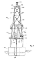
- the subject multi-activity drillship 30 comprises a tanker-type hull 32 which is fabricated with a large moon pool 34 between the bow 36 and stern 38.
- a multi-activity derrick 40 is mounted upon the drillship substructure above a moon pool 34 and operable to conduct primary tubular operations and simultaneously operations auxiliary to primary tubular operations from a single derrick through the moon pool.
- tubular is used as a generic expression for conduits used in the drilling industry and includes relative large riser conduits, casing and drillstrings of various diameters.
- the drillship 30 may be maintained on station by being moored, or by being turret moored such as disclosed, for example, in the above-referenced Richardson United States Patent Nos. 3,191,201 and 3,279,404 .
- the drillship 30 is accurately maintained on station by being dynamically positioned. Dynamic positioning is performed by utilizing a plurality of bow thrusters 42 and stern thrusters 44 which are accurately controlled by computers utilizing input data to control the multiple degrees of freedom of the floating vessel in varying environmental conditions of wind, current, wave swell, etc. Dynamic positioning is relatively sophisticated and by utilizing satellite references is capable of very accurately maintaining a drillship at a desired latitude and longitude, on station, over a well-head.
- Figure 2 discloses a starboard elevation of the multi-activity drillship which includes an aft heliport 46 above ship space 50 and a main engine room 52.
- Riser storage racks 54 are positioned above an auxiliary engine room 56.
- First 58 and second 60 pipe racks are positioned in advance of the riser storage area 54 and above an auxiliary machine room 62, warehouse and sack stores 64 and mud rooms 66.
- a shaker house 68 extends above the mud room 66 and adjacent to an aft portion of the multi-activity derrick 40.
- a first 70 and second 72 75-ton (68 metric tons) crane, with 150-foot (45.7 meter) booms, are mounted aft of the multi-activity derrick 40 and operably are utilized, for example, in connection with the riser and pipe handling requirements of the operating drillship.
- a machinery room and well testing area 74 is constructed adjacent to a forward edge of the multi-activity drill derrick 40 and an additional riser storage area 76 and crew quarters 78 are positioned forward of the well testing area as shown in Figure 2 .
- Another 75-ton (68 metric tons) crane 82 is positioned forward of the multi-activity derrick 40 and operably services a forward portion of the drillship.
- FIG. 3 a plan view of the drillship 30, an aft heliport 46 is shown above ship space 50 and aft of a riser storage area 54.
- a second riser storage area 55 is positioned adjacent storage 54 and in a similar vein pipe racks 63 and 65 are positioned adjacent to previously noted pipe racks 62 and 64 respectively.
- the shaker house 68 is forward of the pipe racks and adjacent to the multi-activity derrick 40 and a mudlogger 67 is shown above the mud room 66.
- a catwalk 69 extends between the riser and pipe rack to facilitate transport of riser lengths, casing and drillpipe from the storage areas to the multi-purpose derrick 40.
- a well-testing area 74 and 75 is shown adjacent to the derrick 40 and aft of approximately 10,000 additional feet ( 3000 meters) of tubular storage racks 76 and 77.
- a forward heliport 80 is shown positioned above crew quarters 78, as previously discussed, and the forward tubular area is serviced by a 75-ton (68 metric tons) crane 82 as noted above.
- a plan view of the machinery deck is shown in Figure 4 and includes an engine room 56 having fuel tanks on the starboard side and a compressed air and water maker system 84 on the port side.
- Auxiliary machinery 62 such as a machine shop, welding shop, and air conditioning shop are shown positioned adjacent to switching gear, control modules and SCR room 86.
- an air conditioning warehouse 88 In front of the SCR room, in the machinery deck is an air conditioning warehouse 88 and stack stores 64 as previously noted.
- the mudpump rooms 66 include a plurality of substantially identical drilling mud and cement pumps 90 and mixing and storage tanks 92.
- the derrick footprint 94, 96, 98, and 100 is shown in the cellar deck and is symmetrically positioned about a moon pool area 34.
- a parallel runway extends over the moon pool and is laid between an aft subsea tree systems area and a fore subsea room area.
- a riser compressor room 102 is shown in a position adjacent to the forward machinery area 74 which includes a blowout preventer control area 104.
- the drilling hull may be eight hundred and fifty feet (260 meters) in length and of a design similar to North Sea shuttle tankers.
- the various modularized packages of components are facilely contained within a ship of this capacity and the dynamically positioned drillship provides a large stable platform for deep water drilling operations.
- the foregoing multi-activity drillship and operating components are disclosed in an illustrative arrangement and it is envisioned that other equipment may be utilized and positioned in different locations, another ship design or platform designs. However, the foregoing is typical of the primary operating facilities which are intended to be included with the subject multi-activity drillship.
- the derrick 40 includes a base 110 which is joined to the drillship substructure 112 symmetrically above the moon pool 34.
- the base 110 is preferably square and extends upwardly to a drill floor level 114.
- Above the drill floor level is a drawworks platform 116 and a drawworks platform roof 118.
- Derrick legs 120, 122, 124, and 126 are composed of graduated tubular conduits and project upwardly and slope inwardly from the drill floor 114.
- the derrick terminates into a generally rectangular derrick top structure or deck 128.
- the legs are spatially fixed by a network of struts 130 to form a rigid drilling derrick for heavy duty tubular handling and multi-activity functions in accordance with the subject invention.
- the derrick top 128 serves to carry a first 132 and second 134 mini-derrick which guide a sheave and hydraulic motion compensation system.
- the multi-activity derrick 40 preferably includes a first 140 and second 142 drawworks of a conventional design.
- a cable 144 extends upwardly from the drawworks 140 over sheaves 146 and 148 and motion compensated sheaves 150 at the top of the derrick 40.
- the drawwork cabling extends downwardly within the derrick to first 152 and second 154 travelling blocks, note again Figure 5 .
- Each of the drawworks 140 and 142 is independently controlled by distinct driller consoles 156 and 158 respectively.
- the derrick drilling floor 114 includes, first and second tubular advancing stations 160 and 162 which in one embodiment, comprises a first (161) rotary table and a second (163), substantially identical, rotary table.
- the rotary tables are positioned in a mutually spaced relationship, symmetrically, within the derrick 40 and, in one embodiment, along a center line of the drillship 30.
- Each tubular advancing station includes, in one embodiment, a rotary machine, rotary drive, master bushings, kelly drive bushings and slips.
- each tubular advancing station 160 and 162 operably includes an iron roughneck, a pipe tong, a spinning chain, a kelly and a rotary swivel for making up and tearing down tubulars in a conventional manner.
- a first pipe handling apparatus 164 and a second pipe handling apparatus 166 is positioned, in one embodiment upon a rail 168 which extends from a location adjacent to the first tubular advancing means 160 to the second tubular advancing means 162.
- a first conduit setback envelope 170 is located adjacent to said first pipe-handling apparatus 164 and a second pipe setback envelope 172 is positioned adjacent to the second pipe handling apparatus 166.
- a third conduit setback envelope 174 may be positioned between the first setback envelope 170 and the second setback envelope 172 and is operable to receive conduits from either of said first conduit handling apparatus 164 or said second conduit handling apparatus 166 as they translate upon the rail 168.
- first tubular advancing station 160 Positioned adjacent the first tubular advancing station 160 is a first iron roughneck 180 and a second iron roughneck 181 is positioned adjacent to the second tubular advancing station 162.
- the iron roughnecks are operably utilized in cooperation with the rotary stations 160 and 162, respectively to make-up and break down tubulars.
- the rail 168 permits the first tubular handling assembly 164 to setback and receive conduit from any of the tubular setback envelopes 170, 172, and 174.
- the primary utilization for pipe handling assembly 164 will be with respect to setback envelopes 170 and 174.
- the rail 168 permits the second tubular handling assembly 166 to transfer conduits such as riser, casing, or drill pipe between the second rotary station 162 and tubular setback envelopes 172, 174, and 170, however, the tubular handling assembly 166 will be utilized most frequently with conduit setback envelopes 172 and 174.
- tubular handling arrangements are contemplated by the subject invention, such as a rugged overhead crane structure within the derrick 40.
- a common element however, among all systems will be the ability to make-up and break down tubulars at both the first and second tubular stations for advancing tubulars through the moon pool.
- a characteristic of tubular handling systems will be the ability to pass tubular segments back and forth between the first station for advancing tubulars through the moon pool and the second station for advancing tubulars and the setback envelopes as discussed above.
- the rotary function is applied to tubulars performed by a first 182 and second 183 top drive device, note again Figure 5 .
- Each top drive device is similar and the unit 182 is shown more particularly in Figure 8 .
- the top drive is connected to traveling block 152 and is balanced by hydraulic balancing cylinders 184.
- a guide dolly 185 supports a power train 186 which drives a tubular handling assembly 188 above drill floor 114.
- top drive system is presently preferred. In certain instances, both systems may even be installed on a drillship. Still further, other systems may ultimately be envisioned, however, an operational characteristic of all tubular systems will be the ability to independently handle, make-up or break down, set back, and advance tubulars through multi-stations over of a moon pool and into the seabed.
- the multi-activity derrick 40 comprises two identical top drives and/or separate rotary tables, drawworks, motion compensation and travelling blocks positioned within a single, multi-purpose derrick. Accordingly, the subject invention enables primary drilling activity and auxiliary activity to be conducted simultaneously and thus the critical path of a drilling function to be conducted through the moon pool 34 may be optimized. Alternatively, units are envisioned which will not be identical in size or even function, but are nevertheless capable of handling tubulars and passing tubulars back and forth between tubular advancing stations within a single derrick. Further, in a preferred embodiment, the multi-activity support structure is in the form of a four sided derrick.
- the subject invention is intended to include other superstructure arrangements such as tripod assemblies or even two adjacent upright but interconnected frames and superstructures that are operable to perform a support function for more than one tubular drilling or activity for conducting simultaneous operations through the deck of a drillship, semi-submersible tension leg platform, or the like.
- a first or main tubular advancing means (160) is operable to conduct primary drilling activity and a second or auxiliary tubular advancing means (162) is utilized for functions critical to the drilling process but can be advantageously removed from the drilling critical path to dramatically shorten overall drilling time.
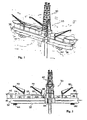
- Figure 9 there is shown by a schematic cartoon a multi-activity derrick 40 positioned upon a drilling deck 190 of a drillship, semi-submersible, tension leg platform, or the like, of the type discussed above.
- a moon pool opening in the drilling deck 192 enables tubulars such as risers, casing or drill pipe to be made up within the derrick 40 and extended through a body of water 194 to conduct drilling activity and/or activity associated with drilling within and upon the seabed 196.
- the main drilling station 160 is utilized to pick up and make up a thirty inch (76.2 cm) jetting assembly for jetting into the seabed and twenty six inch (66 cm) drilling assemblies and places them within the derrick setback envelopes for the auxiliary station 162 to run inside of thirty inch (76.2 cm) casing.
- the main rig then proceeds to make up eighteen and three fourths inch (47.6 cm) wellhead and stands it back in the derrick for the twenty inch (50.8 cm) tubular casing run.
- auxiliary station 162 is used to pick up the thirty inch (76.2 cm) casing and receives the jetting assembly from the main rig and runs the complete assembly to the seabed where it begins a thirty inch ( 76.2 cm) casing jetting operation.
- the main rig skids a blowout preventer stack 200 under the rig floor and carries out a functioning test on the stack and its control system.
- the auxiliary rig and rotary station 162 are used to jet in and set the thirty inch (76.2 cm) casing.
- the auxiliary rig then disconnects the running tool from the wellhead and drills ahead the twenty six inch (66 cm) hole section.
- the main rig is utilized to start running the blowout preventer stack 200 and drilling riser to the seabed.
- the auxiliary rig including second rotary station 162 is utilized to complete drilling of the twenty six inch (66 cm) hole section and then pulls the twenty six inch (66 cm) drilling assembly to the surface.
- the auxiliary station then rigs up and runs twenty inch (50.8 cm) tubular casing 202 and after landing the twenty inch (50.8 cm) casing in the wellhead the auxiliary rig then hooks up cement lines and cements the twenty inch (50.8 cm) casing in place.
- the auxiliary rig then retrieves the twenty inch (50.8 cm) casing landing string.
- the main rig and rotary station 160 lands the blowout-preventer 200 onto the wellhead and tests the wellhead connection.
- the auxiliary rotary station 162 is utilized to disemble the thirty inch (76.2 cm) jetting and twenty six inch (66 cm) drilling assembly. After this operation is complete the auxiliary rotary station 162 is utilized to makeup a seventeen and one half inch (44.45 cm) bottom hole assembly and places the assembly in the derrick for the primary or main rotary assembly to pick up.
- the main rotary assembly (160) picks up the seventeen and one half inch (44.45 cm) hole section bottom hole assembly 204, which was previously made up by the auxiliary rig, and the main rotary assembly runs this and drillpipe in the hole to begin drilling the seventeen and one half inch (44.45 cm) section.
- the auxiliary rotary station picks up single joints of thirteen and three eighths inch (34 cm) casing from the drillship pipe racks, makes them up into one hundred and twenty five foot ( 38 m) lengths and then stands the lengths back in the derrick envelopes in preparation for the thirteen and three eighths inch (34 cm) casing run.
- the main rotary station 160 completes drilling the seventeen and one half inch (44.45 cm) hole section.
- the drilling assembly is then retrieved back to the surface through the moon pool and the main rotary station then proceeds to rig up and run the thirteen and three eighths inch (34 cm) casing segments which were previously made up and set back within the derrick.
- the rig cements the casing in place.
- the auxiliary rotary station 162 picks up single joints of nine and five eighths inch (24.46 cm) casing from the drillship pipe racks, makes them up into triples and then stands them back in the derrick tubular handling envelopes in preparation for a nine and five eighths inch (24.46 cm) casing run.
- the primary rotary station tests the blowout preventer stack after setting the thirteen and three eighths inch (34 cm) seal assembly and the auxiliary rotary station changes the bottom hole assembly from seventeen and one half inches (44.45 cm) to twelve and one quarter inch (31 cm) assembly.
- the twelve and one quarter inch (31 cm) assembly is then set back in the derrick conduit handling envelopes in a position where it can be picked up by the main rotary station.
- the primary rotary station 160 is used to run in the hole with twelve and one quarter inch (31 cm) bottom hole assembly and begins drilling the twelve and one quarter inch (31 cm) hole section.
- the auxiliary rotary station is utilized to make up nine and five eighths inch (24.46 cm) casing running tool and cement head and then stands both of these complete assemblies back in the conduit handling envelopes of the derrick in preparation for a nine and five eighths inch (24.46 cm) casing run.
- the primary rotary station 160 is utilized to complete drilling the twelve and one quarter inch (31 cm) hole section and retrieves the twelve and one quarter inch (31 cm) assembly back to the surface.
- the primary rotary station then rigs up and runs the nine and five eighths inch (24.46 cm) casing in the hole and cements the casing in place.
- the auxiliary rotary station changes the bottom hole assembly from twelve and one quarter inch (31 cm) to eight and one half-inch (21.6 cm) and stands the eight and one half-inch (21.6 cm) assemblies back in the derrick to be picked up by the primary rotary station.
- Figure 18 the primary rotary station is shown running in the hole with eight and one half-inch (21.6 cm) drilling assemblies and begins to drill the eight and one half-inch (21.6 cm) hole with the first rotary top drive. During this operation the auxiliary rotary station is used to make up a casing cutter.
- the primary rotary station 160 completes drilling the eight and one half (21.6 cm) inch hole section and retrieves the drilling assembly back to the surface. The primary rotary station then proceeds to rig down the riser and begins to recover the blowout preventer stack 200.
- the primary rotary station is used to continue recovering the blowout preventer stack 200 and the auxiliary rotary station is used to recover the wellhead 212.
- FIG. 23a there will be seen an illustrative time chart of typical drilling activity for an offshore well in accordance with a conventional drilling operation.
- the filled in horizontal bars represent time frames along an abscissa and tubular activity is shown along an ordinate.
- note bar 220 As an initial operation, eight hours, note bar 220, are utilized to pick up pipe and twenty seven hours, note bar 222, are then required to jet drill thirty inch (76.2 cm) casing in place. Three hours are then used to make up and lay down bottom hole assemblies and running tools, see time bar 224.
- forty four and one half hours, note bar 226, are required to drill and cement twenty inch (50.8 cm) casing.
- Sixty-nine hours 228 are necessary to run and test a blowout preventer.
- note bar 230 Three hours are required to make up and lay down bottom hole assemblies and running tools, see time bar 230.
- note bar 234, and twenty one hours, note bar 236, are used to run and cement thirteen and three eighths inch (34 cm) casing.
- note bar 238, and ten and one half hours are used to test the blowout preventer, note bar 240.
- note bar 242 eighty one and one half hours, note bar 242, are utilized to drill twelve and one quarter inch (31 cm) drill string and twenty two hours are used to run and cement nine and five eighths inch (24.46 cm) casing, note bar 244.
- an identical drilling operation is depicted by a time chart in Figure 23b in accordance with the subject invention, where a main and auxiliary tubular station are simultaneously utilized in a preferred embodiment of the subject invention, to dramatically decrease the overall drilling time and thus increase efficiency of the drilling operation. More specifically, it will be seen that the main drilling operation can be conducted through a first tubular advancing station and the critical path of the drilling sequence is depicted with solid time bars whereas auxiliary activity through a second tubular advancing station is shown by crossed hatched time bars.
- the next operation requires ten and one half hours to test the blowout preventer, as shown by time bar 272.
- Eighty one and one half hours are used by the primary rotary station and rotary table 160 to drill the twelve and one quarter inch (31 cm) hole as depicted by time bar 274.
- Time bar 276 discloses sixteen hours to run and cement the nine and five eighths inch (24.46 cm) casing.
- An eight and one half inch (21.6 cm) drill hole then consumes fourteen hours, as depicted by time bar 278 and finally the main rig utilizes thirty and one half hours as depicted by time bar 280 to recover the blowout preventer.
- the second or auxiliary tubular-advancing station 162 is used to jet drill the thirty inch (76.2 cm) casing in twenty one and one half hours as shown by hashed time bar 282. Then the twenty inch (50.8 cm) casing is drilled and run during a period of forty four and one half hours as shown by time bar 284. The auxiliary rig is then used for five hours to make up and lay down bottom hole assemblies and running tools for five hours as shown by time bar 286. Eight and one half hours are used to set back thirteen and three eighths inch (34 cm) doubles as shown in time bar 288.
- Time bar 290 illustrates the use of four and one quarter hours to make up and lay down bottom hole assemblies and running tools, and ten hours are required, as shown in time bar 292, to set back nine and five eighths inch (24.46 cm) doubles.
- Four hours are then required as shown by time bar 300 to make up and lay down bottom hole assemblies and running tools and then nine and one half hours are used to make up and run a casing cutter as depicted by time bar 302.
- the wellhead is then recovered in six and one half hours as shown on time bar 304 and finally eight hours are utilized as depicted in time frame 206 to lay down the drill string.
- the critical path has been substantially reduced.
- the time savings comprises a twenty nine percent reduction in time for a drilling operation.
- this time sequence could be longer or shorter, but it will be appreciated by those of ordinary skill in the art that as the depth of water increases, the advantage of a multi-activity drilling method and apparatus in accordance with the subject invention increases.
- the enhanced drilling time, and thus cost savings, is provided by the multi-activity derrick having substantially identical tubular advancing stations wherein primary drilling activity can be conducted within the derrick and auxiliary activity concomitantly conducted from the same derrick and through the same moon pool.
- the derrick includes dual rotary stations, and in a preferred embodiment, top drives and a dual tubular handling system.
- a plurality of tubular set back envelopes are positioned adjacent the dual rotary station, and first and second conduit handling assemblies operably transfer riser segments, casing, and drillpipe assemblies between the first and second tubular advancing stations and any of the set back envelopes.
- the dual derrick drawworks are independently controlled by substantially identical drill consoles mounted upon the drilling floor of the derrick such that independent operations can be performed simultaneously by a main drilling rotary station through a moon pool while auxiliary operations can be simultaneously conducted through a second rotary station and the moon pool.
- the multi-station derrick enables a driller to move many rotary operations out of the critical path such as blowout prevention and riser running while drilling a top hole; making up bottom hole assemblies or running tools with an auxiliary rotary while drilling with a primary rotary station; making up and standing back casing with the auxiliary rotary while drilling with the primary rotary assembly; test running; measurements while drilling while continuing primary drilling activity; and deploying a high-pressure second stack/riser outside of primary rig time.
- the multi-station derrick permits an operator to rig up to run trees with the auxiliary rotary station while carrying out normal operations with a primary rotary station; running a subsea tree to the bottom with the auxiliary rotary station while completing riser operations and simultaneously running two subsea trees, bases, etc.
Landscapes
- Engineering & Computer Science (AREA)
- Life Sciences & Earth Sciences (AREA)
- Mining & Mineral Resources (AREA)
- Geology (AREA)
- Geochemistry & Mineralogy (AREA)
- General Life Sciences & Earth Sciences (AREA)
- Mechanical Engineering (AREA)
- Physics & Mathematics (AREA)
- Environmental & Geological Engineering (AREA)
- Fluid Mechanics (AREA)
- Signal Processing (AREA)
- Multimedia (AREA)
- Chemical & Material Sciences (AREA)
- Civil Engineering (AREA)
- Structural Engineering (AREA)
- Architecture (AREA)
- Combustion & Propulsion (AREA)
- Ocean & Marine Engineering (AREA)
- Earth Drilling (AREA)
- Drilling And Boring (AREA)
- Geophysics And Detection Of Objects (AREA)
Claims (6)
- Verfahren zum Durchführen von Offshore-Bohroperationen mit einer Mehrfachaktivitäts-Bohranordnung, die betrieben werden kann, um auf einem Bohrdeck (190) montiert zu sein, das oberhalb der Oberfläche eines Wasserkörpers positioniert ist, und mit einem ersten röhrenförmigen Vorschubmittel (160) und einem zweiten röhrenförmigen Vorschubmittel (162), wobei das Verfahren die folgenden Schritte umfasst:(a) Vorschieben röhrenförmiger Elemente durch das erste röhrenförmige Vorschubmittel (160) in den Wasserkörper (194) und in das Bett (196) des Wasserkörpers, um primäre Bohroperationen für ein einzelnes Bohrloch durchzuführen,(b) Vorschieben röhrenförmiger Elemente durch das zweite röhrenförmige Vorschubmittel (162) in den Wasserkörper (194) und in das Bett (196) des Wasserkörpers (194), um eine die primäre Bohraktivität für das einzelne Bohrloch unterstützende Aktivität durchzuführen; und(c) Transferieren röhrenförmiger Elemente zwischen dem ersten röhrenförmigen Vorschubmittel (160) und dem zweiten röhrenförmigen Vorschubmittel (162);wobei die primäre Bohraktivität zumindest teilweise durchgeführt wird, indem röhrenförmige Elemente von dem ersten röhrenförmigen Vorschubmittel (160) vorgeschoben werden, und die unterstützende Bohraktivität gleichzeitig für das einzelne Bohrloch durchgeführt wird, indem röhrenförmige Elemente zu dem Bett (196) des Wasserkörpers von dem zweiten röhrenförmigen Vorschubmittel (162) vorgeschoben werden.
- Verfahren zum Durchführen von Offshore-Bohroperationen, wie es in Anspruch 1 definiert ist, wobei das Verfahren ferner dadurch gekennzeichnet ist, dass
der Schritt des Vorschiebens der röhrenförmigen Elemente von dem ersten Vorschubmittel (160) ein Rotieren der röhrenförmigen Elemente mit einem ersten Aufsatzantrieb (182), der von einem aufrechten Decksaufbau gehalten wird, enthält. - Verfahren zum Durchführen von Offshore-Bohroperationen, wie es in Anspruch 2 definiert ist, wobei das Verfahren ferner dadurch gekennzeichnet ist, dass
der Schritt des Vorschiebens der röhrenförmigen Elemente von dem zweiten Vorschubmittel (162) ein Rotieren der röhrenförmigen Elemente mit einem zweiten Aufsatzantrieb (182), der von einem aufrechten Decksaufbau gehalten wird, enthält. - Verfahren zum Durchführen von Offshore-Bohroperationen, wie es in Anspruch 1 definiert ist, wobei das Verfahren ferner dadurch gekennzeichnet ist, dass
der Schritt des Vorschiebens röhrenförmiger Elemente von dem ersten (160) und zweiten (162) röhrenförmigen Vorschubmittel ein Rotieren röhrenförmiger Elemente an dem ersten röhrenförmigen Vorschubmittel (160) mit einem Rotationstisch (161); und
ein Rotieren röhrenförmiger Elemente an dem zweiten röhrenförmigen Vorschubmittel (162) mit einem zweiten Rotationstisch (163) enthält. - Verfahren zum Durchführen von Offshore-Bohroperationen in das Bett (196) eines Wasserkörpers für ein einzelnes Bohrloch von einem Bohrdeck (190), das betrieben werden kann, um oberhalb der Oberfläche des Wasserkörpers positioniert zu sein, wobei das Verfahren zumindest teilweise von einem ersten Mittel (160) zum Vorschieben röhrenförmiger Elemente und zumindest teilweise von einem zweiten Mittel (162) zum Vorschieben röhrenförmiger Elemente durchgeführt wird, wobei beide Vorschubmittel (160,162) innerhalb eines Decksaufbaus positioniert sind, wobei das Verfahren zum Durchführen von Bohroperationen die folgenden Schritte umfasst:(a) Bohren (284) zumindest eines Abschnitts eines Bohrlochs in das Bett (196) des Wasserkörpers von entweder dem ersten oder zweiten Mittel (160, 162) zum Vorschieben röhrenförmiger Elemente;(b) Führen (284) zumindest eines Bohrrohrs von dem entweder ersten oder zweiten Mittel (160, 162) zum Vorschieben röhrenförmiger Elemente in zumindest einen Abschnitt des Bohrlochs; und gekennzeichnet durch die folgenden Schritte:(c) gleichzeitig, während zumindest eines Abschnitts des Zeitraums, der zum Durchführen der Schritte (a) und (b) verwendet wird, Führen (264) eines Blowout-Verhinderers (200) und eines Steigrohrs in den Wasserkörper von dem anderen des ersten oder zweiten Mittels zum Vorschieben röhrenförmiger Elemente (160, 162) in eine Position in der Nähe zumindest des Abschnitts des Bohrlochs in dem Bett des Wasserkörpers (196);
wobei die Ereignisse von Schritt (c) unabhängig von und während zumindest eines Abschnitts desselben Zeitraums durchgeführt werden, wie die Ereignisse von Schritten (a) und (b), um die Gesamtzeit zu reduzieren, die nötig ist, um Schritte (a) bis (c) durchzuführen, um Offshore-Bohroperationen von dem Bohrdeck (190) an einem einzelnen Bohrloch, das in das Bett (196) des Wasserkörpers gebohrt wird, durchzuführen; und(d) Landen (266) des Blowout-Verhinderers (200) und des Steigrohrs auf das Bohrloch von dem anderen des ersten oder zweiten Mittels zum Vorschieben. - Verfahren zum Durchführen von Offshore-Bohroperationen in das Bett (196) eines Wasserkörpers für ein einzelnes Bohrloch von einem Bohrdeck (190), das betrieben werden kann, um oberhalb der Oberfläche des Wasserkörpers positioniert zu sein, wie es in Anspruch 5 definiert ist, wobei das Verfahren ferner dadurch gekennzeichnet ist, dass die Schritte (b) und (c) im Wesentlichen zeitgleich fertig gestellt werden.
Priority Applications (4)
| Application Number | Priority Date | Filing Date | Title |
|---|---|---|---|
| EP10180220A EP2332822A3 (de) | 1996-05-03 | 1997-01-27 | Bohrshiff oder halbeintauchbare Bohrinsel und Bohranordnung für vielfältige Operationen |
| EP08004481A EP1925549A3 (de) | 1996-05-03 | 1997-01-27 | Bohrschiff oder halb tauchfähige und mehrfach aktivierbare Bohranordnung |
| EP02022449A EP1277913B1 (de) | 1996-05-03 | 1997-01-27 | Bohrshiff oder halbeintauchbare Bohrinsel und Bohranordnung für vielfältige Operationen |
| EP01114469A EP1148206A3 (de) | 1996-05-03 | 1997-01-27 | Verfahren und Vorrichtung für vielfältige Operationen bei Explorations- und/oder Entwicklungsbohrungen in der See |
Applications Claiming Priority (3)
| Application Number | Priority Date | Filing Date | Title |
|---|---|---|---|
| US642417 | 1991-01-17 | ||
| US08/642,417 US6085851A (en) | 1996-05-03 | 1996-05-03 | Multi-activity offshore exploration and/or development drill method and apparatus |
| PCT/US1997/000537 WO1997042393A1 (en) | 1996-05-03 | 1997-01-27 | Multi-activity offshore exploration and/or development drilling method and apparatus |
Related Child Applications (2)
| Application Number | Title | Priority Date | Filing Date |
|---|---|---|---|
| EP02022449A Division EP1277913B1 (de) | 1996-05-03 | 1997-01-27 | Bohrshiff oder halbeintauchbare Bohrinsel und Bohranordnung für vielfältige Operationen |
| EP01114469A Division EP1148206A3 (de) | 1996-05-03 | 1997-01-27 | Verfahren und Vorrichtung für vielfältige Operationen bei Explorations- und/oder Entwicklungsbohrungen in der See |
Publications (4)
| Publication Number | Publication Date |
|---|---|
| EP0836668A1 EP0836668A1 (de) | 1998-04-22 |
| EP0836668A4 EP0836668A4 (de) | 1998-08-05 |
| EP0836668B1 EP0836668B1 (de) | 2003-01-22 |
| EP0836668B2 true EP0836668B2 (de) | 2009-12-16 |
Family
ID=24576465
Family Applications (5)
| Application Number | Title | Priority Date | Filing Date |
|---|---|---|---|
| EP02022449A Revoked EP1277913B1 (de) | 1996-05-03 | 1997-01-27 | Bohrshiff oder halbeintauchbare Bohrinsel und Bohranordnung für vielfältige Operationen |
| EP01114469A Withdrawn EP1148206A3 (de) | 1996-05-03 | 1997-01-27 | Verfahren und Vorrichtung für vielfältige Operationen bei Explorations- und/oder Entwicklungsbohrungen in der See |
| EP97903797A Expired - Lifetime EP0836668B2 (de) | 1996-05-03 | 1997-01-27 | Multioperationsverfahren für die ausführung von explorations- und/oder entwicklungsbohrungen im offshore-bereich |
| EP10180220A Withdrawn EP2332822A3 (de) | 1996-05-03 | 1997-01-27 | Bohrshiff oder halbeintauchbare Bohrinsel und Bohranordnung für vielfältige Operationen |
| EP08004481A Withdrawn EP1925549A3 (de) | 1996-05-03 | 1997-01-27 | Bohrschiff oder halb tauchfähige und mehrfach aktivierbare Bohranordnung |
Family Applications Before (2)
| Application Number | Title | Priority Date | Filing Date |
|---|---|---|---|
| EP02022449A Revoked EP1277913B1 (de) | 1996-05-03 | 1997-01-27 | Bohrshiff oder halbeintauchbare Bohrinsel und Bohranordnung für vielfältige Operationen |
| EP01114469A Withdrawn EP1148206A3 (de) | 1996-05-03 | 1997-01-27 | Verfahren und Vorrichtung für vielfältige Operationen bei Explorations- und/oder Entwicklungsbohrungen in der See |
Family Applications After (2)
| Application Number | Title | Priority Date | Filing Date |
|---|---|---|---|
| EP10180220A Withdrawn EP2332822A3 (de) | 1996-05-03 | 1997-01-27 | Bohrshiff oder halbeintauchbare Bohrinsel und Bohranordnung für vielfältige Operationen |
| EP08004481A Withdrawn EP1925549A3 (de) | 1996-05-03 | 1997-01-27 | Bohrschiff oder halb tauchfähige und mehrfach aktivierbare Bohranordnung |
Country Status (18)
| Country | Link |
|---|---|
| US (4) | US6085851A (de) |
| EP (5) | EP1277913B1 (de) |
| JP (1) | JP3002545B2 (de) |
| KR (1) | KR100302149B1 (de) |
| CN (1) | CN1079483C (de) |
| AP (1) | AP1278A (de) |
| AU (1) | AU710636B2 (de) |
| BR (2) | BR9706592A (de) |
| CA (1) | CA2225755C (de) |
| DE (2) | DE69718592D1 (de) |
| DK (2) | DK0836668T4 (de) |
| ES (2) | ES2300409T3 (de) |
| MX (1) | MX9800111A (de) |
| NO (4) | NO313207B3 (de) |
| NZ (1) | NZ329650A (de) |
| OA (1) | OA10649A (de) |
| PT (1) | PT1277913E (de) |
| WO (1) | WO1997042393A1 (de) |
Families Citing this family (191)
| Publication number | Priority date | Publication date | Assignee | Title |
|---|---|---|---|---|
| US7100710B2 (en) | 1994-10-14 | 2006-09-05 | Weatherford/Lamb, Inc. | Methods and apparatus for cementing drill strings in place for one pass drilling and completion of oil and gas wells |
| US7013997B2 (en) | 1994-10-14 | 2006-03-21 | Weatherford/Lamb, Inc. | Methods and apparatus for cementing drill strings in place for one pass drilling and completion of oil and gas wells |
| US7108084B2 (en) | 1994-10-14 | 2006-09-19 | Weatherford/Lamb, Inc. | Methods and apparatus for cementing drill strings in place for one pass drilling and completion of oil and gas wells |
| US7147068B2 (en) | 1994-10-14 | 2006-12-12 | Weatherford / Lamb, Inc. | Methods and apparatus for cementing drill strings in place for one pass drilling and completion of oil and gas wells |
| US7228901B2 (en) | 1994-10-14 | 2007-06-12 | Weatherford/Lamb, Inc. | Method and apparatus for cementing drill strings in place for one pass drilling and completion of oil and gas wells |
| US7036610B1 (en) | 1994-10-14 | 2006-05-02 | Weatherford / Lamb, Inc. | Apparatus and method for completing oil and gas wells |
| US6868906B1 (en) | 1994-10-14 | 2005-03-22 | Weatherford/Lamb, Inc. | Closed-loop conveyance systems for well servicing |
| US7040420B2 (en) | 1994-10-14 | 2006-05-09 | Weatherford/Lamb, Inc. | Methods and apparatus for cementing drill strings in place for one pass drilling and completion of oil and gas wells |
| JP3187726B2 (ja) * | 1996-12-05 | 2001-07-11 | 日本海洋掘削株式会社 | 大水深掘削用複合型パイプ揚降装置 |
| US7509722B2 (en) | 1997-09-02 | 2009-03-31 | Weatherford/Lamb, Inc. | Positioning and spinning device |
| US7140445B2 (en) | 1997-09-02 | 2006-11-28 | Weatherford/Lamb, Inc. | Method and apparatus for drilling with casing |
| US6742596B2 (en) | 2001-05-17 | 2004-06-01 | Weatherford/Lamb, Inc. | Apparatus and methods for tubular makeup interlock |
| US6536520B1 (en) | 2000-04-17 | 2003-03-25 | Weatherford/Lamb, Inc. | Top drive casing system |
| US6273193B1 (en) * | 1997-12-16 | 2001-08-14 | Transocean Sedco Forex, Inc. | Dynamically positioned, concentric riser, drilling method and apparatus |
| GB9815809D0 (en) | 1998-07-22 | 1998-09-16 | Appleton Robert P | Casing running tool |
| FR2782341B1 (fr) | 1998-08-11 | 2000-11-03 | Technip Geoproduction | Installation d'exploitation d'un gisement en mer et procede d'implantation d'une colonne montante |
| DE19837692C2 (de) | 1998-08-19 | 2003-04-03 | Bentec Gmbh Drilling & Oilfield Systems | Bohrvorrichtung, Bohranlage und Verfahren zum Abteufen einer Explorations- und Förderbohrung |
| GB2340859A (en) | 1998-08-24 | 2000-03-01 | Weatherford Lamb | Method and apparatus for facilitating the connection of tubulars using a top drive |
| GB2340857A (en) | 1998-08-24 | 2000-03-01 | Weatherford Lamb | An apparatus for facilitating the connection of tubulars and alignment with a top drive |
| GB2340858A (en) | 1998-08-24 | 2000-03-01 | Weatherford Lamb | Methods and apparatus for facilitating the connection of tubulars using a top drive |
| US6715436B2 (en) | 1998-09-24 | 2004-04-06 | Stolt Offshore Limited | Sea-going vessel and hull for sea-going vessel |
| US7188687B2 (en) | 1998-12-22 | 2007-03-13 | Weatherford/Lamb, Inc. | Downhole filter |
| WO2000037766A2 (en) | 1998-12-22 | 2000-06-29 | Weatherford/Lamb, Inc. | Procedures and equipment for profiling and jointing of pipes |
| GB2345074A (en) | 1998-12-24 | 2000-06-28 | Weatherford Lamb | Floating joint to facilitate the connection of tubulars using a top drive |
| GB2347441B (en) | 1998-12-24 | 2003-03-05 | Weatherford Lamb | Apparatus and method for facilitating the connection of tubulars using a top drive |
| US7311148B2 (en) | 1999-02-25 | 2007-12-25 | Weatherford/Lamb, Inc. | Methods and apparatus for wellbore construction and completion |
| US6896075B2 (en) | 2002-10-11 | 2005-05-24 | Weatherford/Lamb, Inc. | Apparatus and methods for drilling with casing |
| US6857487B2 (en) | 2002-12-30 | 2005-02-22 | Weatherford/Lamb, Inc. | Drilling with concentric strings of casing |
| US6325146B1 (en) * | 1999-03-31 | 2001-12-04 | Halliburton Energy Services, Inc. | Methods of downhole testing subterranean formations and associated apparatus therefor |
| US6443240B1 (en) * | 1999-10-06 | 2002-09-03 | Transocean Sedco Forex, Inc. | Dual riser assembly, deep water drilling method and apparatus |
| US7216727B2 (en) | 1999-12-22 | 2007-05-15 | Weatherford/Lamb, Inc. | Drilling bit for drilling while running casing |
| GB9930450D0 (en) * | 1999-12-23 | 2000-02-16 | Eboroil Sa | Subsea well intervention vessel |
| US7334650B2 (en) | 2000-04-13 | 2008-02-26 | Weatherford/Lamb, Inc. | Apparatus and methods for drilling a wellbore using casing |
| US7325610B2 (en) | 2000-04-17 | 2008-02-05 | Weatherford/Lamb, Inc. | Methods and apparatus for handling and drilling with tubulars or casing |
| US7025147B2 (en) * | 2000-06-02 | 2006-04-11 | Oil & Gas Rental Services, Inc. | Apparatus for, and method of, landing items at a well location |
| US6378614B1 (en) * | 2000-06-02 | 2002-04-30 | Oil & Gas Rental Services, Inc. | Method of landing items at a well location |
| US7287598B2 (en) * | 2000-06-02 | 2007-10-30 | Allis-Chalmers Energy, Inc. | Apparatus for, and method of, landing items at a well location |
| US6644413B2 (en) | 2000-06-02 | 2003-11-11 | Oil & Gas Rental Services, Inc. | Method of landing items at a well location |
| US6349764B1 (en) | 2000-06-02 | 2002-02-26 | Oil & Gas Rental Services, Inc. | Drilling rig, pipe and support apparatus |
| US6364012B1 (en) * | 2000-06-02 | 2002-04-02 | Oil & Gas Rental Services, Inc. | Drill pipe handling apparatus |
| WO2001094737A1 (en) * | 2000-06-02 | 2001-12-13 | Oil & Gas Rental Services, Inc. | Pipe handling apparatus and method of landing items at a well location |
| GB2365463B (en) | 2000-08-01 | 2005-02-16 | Renovus Ltd | Drilling method |
| NL1016051C2 (nl) * | 2000-08-30 | 2002-03-01 | Huisman Spec Lifting Equip Bv | Dubbel uitgevoerde mast. |
| US6453838B1 (en) * | 2000-10-20 | 2002-09-24 | Ocean Production Technology, Llc | Turret-less floating production ship |
| GB0101259D0 (en) * | 2001-01-18 | 2001-02-28 | Wellserv Plc | Apparatus and method |
| US6494271B2 (en) | 2001-04-25 | 2002-12-17 | Exxonmobil Upstream Research Company | Offshore floating production method |
| AU2002256234B2 (en) * | 2001-05-01 | 2008-03-13 | Itrec, B.V. | Multipurpose unit with multipurpose tower and method for tendering with a semisubmersible |
| AU2003206256B2 (en) * | 2002-02-01 | 2007-11-15 | Sbm Schiedam B.V. | Multi hull barge |
| US6705414B2 (en) | 2002-02-22 | 2004-03-16 | Globalsantafe Corporation | Tubular transfer system |
| US6766860B2 (en) | 2002-02-22 | 2004-07-27 | Globalsantafe Corporation | Multi-activity offshore drilling facility having a support for tubular string |
| NO316183B1 (no) * | 2002-03-08 | 2003-12-22 | Sigbjoern Sangesland | Fremgangsmåte og anordning ved fôringsrör |
| GB0206227D0 (en) | 2002-03-16 | 2002-05-01 | Weatherford Lamb | Bore-lining and drilling |
| US6561112B1 (en) * | 2002-04-22 | 2003-05-13 | Dan T. Benson | System and method for a motion compensated moon pool submerged platform |
| US6994176B2 (en) | 2002-07-29 | 2006-02-07 | Weatherford/Lamb, Inc. | Adjustable rotating guides for spider or elevator |
| US6763898B1 (en) | 2002-08-06 | 2004-07-20 | Itrec B.V. | Dual hoist system |
| US6899186B2 (en) | 2002-12-13 | 2005-05-31 | Weatherford/Lamb, Inc. | Apparatus and method of drilling with casing |
| US7434624B2 (en) | 2002-10-03 | 2008-10-14 | Exxonmobil Upstream Research Company | Hybrid tension-leg riser |
| US7303022B2 (en) | 2002-10-11 | 2007-12-04 | Weatherford/Lamb, Inc. | Wired casing |
| WO2004035375A1 (en) * | 2002-10-16 | 2004-04-29 | Single Buoy Moorings Inc. | Riser installation vessel and method of using the same |
| WO2004044367A2 (en) * | 2002-11-12 | 2004-05-27 | Vetco Gray Inc. | Drilling and producing deep water subsea wells |
| US6955223B2 (en) | 2003-01-13 | 2005-10-18 | Helmerich & Payne, Inc. | Blow out preventer handling system |
| US7128154B2 (en) | 2003-01-30 | 2006-10-31 | Weatherford/Lamb, Inc. | Single-direction cementing plug |
| USRE42877E1 (en) | 2003-02-07 | 2011-11-01 | Weatherford/Lamb, Inc. | Methods and apparatus for wellbore construction and completion |
| WO2004076804A1 (en) | 2003-02-27 | 2004-09-10 | Weatherford/Lamb Inc. | Drill shoe |
| US7503397B2 (en) | 2004-07-30 | 2009-03-17 | Weatherford/Lamb, Inc. | Apparatus and methods of setting and retrieving casing with drilling latch and bottom hole assembly |
| CA2517883C (en) | 2003-03-05 | 2010-01-12 | Weatherford/Lamb, Inc. | Full bore lined wellbores |
| US7874352B2 (en) | 2003-03-05 | 2011-01-25 | Weatherford/Lamb, Inc. | Apparatus for gripping a tubular on a drilling rig |
| US7360594B2 (en) | 2003-03-05 | 2008-04-22 | Weatherford/Lamb, Inc. | Drilling with casing latch |
| CA2517895C (en) | 2003-03-05 | 2009-12-01 | Weatherford/Lamb, Inc. | Casing running and drilling system |
| US7410138B2 (en) * | 2003-03-14 | 2008-08-12 | Tgr Intellectual Properties, Llc | Display adjustably positionable about swivel and pivot axes |
| US6902007B1 (en) * | 2003-03-28 | 2005-06-07 | Helmerich & Payne, Inc. | Blow out preventer transportation |
| WO2004090279A1 (en) | 2003-04-04 | 2004-10-21 | Weatherford/Lamb, Inc. | Method and apparatus for handling wellbore tubulars |
| US7650944B1 (en) | 2003-07-11 | 2010-01-26 | Weatherford/Lamb, Inc. | Vessel for well intervention |
| US7264067B2 (en) | 2003-10-03 | 2007-09-04 | Weatherford/Lamb, Inc. | Method of drilling and completing multiple wellbores inside a single caisson |
| US7284617B2 (en) | 2004-05-20 | 2007-10-23 | Weatherford/Lamb, Inc. | Casing running head |
| DE602005014357D1 (de) * | 2004-06-02 | 2009-06-18 | Stena Drilling Ltd | Anlage für mehrere aktivitäten |
| DE602005006198T2 (de) | 2004-07-20 | 2009-07-09 | Weatherford/Lamb, Inc., Houston | Oberantrieb zur Verbindung von Futterrohren |
| CA2532907C (en) | 2005-01-12 | 2008-08-12 | Weatherford/Lamb, Inc. | One-position fill-up and circulating tool |
| CA2533115C (en) | 2005-01-18 | 2010-06-08 | Weatherford/Lamb, Inc. | Top drive torque booster |
| EP1739279A1 (de) * | 2005-06-30 | 2007-01-03 | Single Buoy Moorings Inc. | Verfahren zum Einrichten eines Steigrohres aus einer Offshore-Produktionsanlage |
| JP4828605B2 (ja) | 2005-08-02 | 2011-11-30 | トランスオーシャン オフショア ディープウォーター ドリリング, インコーポレイテッド | モジュール方式バックアップ流体供給システム |
| RU2418936C2 (ru) | 2005-12-20 | 2011-05-20 | Канриг Дриллинг Текнолоджи, Лтд. | Верхний привод и способ бурения с использованием его |
| WO2007076488A2 (en) | 2005-12-22 | 2007-07-05 | Transocean Offshore Deepwater Drilling Inc | Dual-bop and common riser system |
| CA2586317C (en) | 2006-04-27 | 2012-04-03 | Weatherford/Lamb, Inc. | Torque sub for use with top drive |
| US9670749B2 (en) * | 2006-06-23 | 2017-06-06 | Schlumberger Technology Corporation | Integrated pump assembly for well completion |
| US8925647B2 (en) * | 2006-06-30 | 2015-01-06 | Stena Drilling Ltd. | Triple activity drilling ship |
| SE531718C2 (sv) * | 2006-10-19 | 2009-07-21 | Gva Consultants Ab | Integrerat borrdäck och hantering av utblåsningssäkring |
| US7882902B2 (en) | 2006-11-17 | 2011-02-08 | Weatherford/Lamb, Inc. | Top drive interlock |
| US8122965B2 (en) * | 2006-12-08 | 2012-02-28 | Horton Wison Deepwater, Inc. | Methods for development of an offshore oil and gas field |
| US7802636B2 (en) | 2007-02-23 | 2010-09-28 | Atwood Oceanics, Inc. | Simultaneous tubular handling system and method |
| US20100108322A1 (en) * | 2007-03-26 | 2010-05-06 | Eilertsen Terje W | Parallel drilling and completion for a dry tree floating production facility |
| SE530900C2 (sv) * | 2007-04-02 | 2008-10-14 | Gva Consultants Ab | Borranordning |
| US7628224B2 (en) * | 2007-04-30 | 2009-12-08 | Kellogg Brown & Root Llc | Shallow/intermediate water multipurpose floating platform for arctic environments |
| JP4850970B2 (ja) * | 2007-09-21 | 2012-01-11 | トランスオーシャン セドコ フォレックス ベンチャーズ リミテッド | 付加的な噴出防止装置の制御リダンダンシーを提供するシステムおよび方法 |
| US20090129867A1 (en) * | 2007-11-20 | 2009-05-21 | Millheim Keith K | Self-Standing Riser and Buoyancy Device Deployment and Positioning System |
| CN102123906B (zh) * | 2008-02-15 | 2014-03-26 | 伊特雷科公司 | 海上钻探船 |
| DE502008003345D1 (de) * | 2008-02-19 | 2011-06-09 | Waertsilae Ship Design Germany Gmbh | Arbeitsschiff |
| WO2009117813A1 (en) * | 2008-03-24 | 2009-10-01 | Saxon Energy Services Inc. | System and method for drilling multiple wells |
| US20100135728A1 (en) * | 2008-05-14 | 2010-06-03 | Kingtime Interanational Limited | Mobile offshore drilling and production platform |
| US7921918B2 (en) * | 2008-06-26 | 2011-04-12 | Bryant Jr Charles Larue | Support apparatus for a well bore tool |
| ITPC20080033A1 (it) * | 2008-07-16 | 2010-01-17 | Walter Bagassi | Impianto di perforazione a rotazione del sottosuolo, automatizzato, per ricerche petrolifere, minerarie e idriche, con testa motrice o taglia mosse da una vite senza fine e vite madre trascinate da motori elettrici o idraulici, con contenitori e cari |
| US8181697B2 (en) * | 2008-08-15 | 2012-05-22 | National Oilwell Varco L.P. | Multi-function multi-hole drilling rig |
| US8181698B2 (en) * | 2008-08-15 | 2012-05-22 | National Oilwell Varco L.P. | Multi-function multi-hole drilling rig |
| BRPI0803619B1 (pt) * | 2008-09-19 | 2018-06-12 | Petroleo Brasileiro S.A. - Petrobras | Sistema de execução simultânea de operações em sonda marítima e método |
| US20100150661A1 (en) * | 2008-12-12 | 2010-06-17 | Woolslayer Companies, Inc. | Open face derrick |
| US8256520B2 (en) * | 2009-01-14 | 2012-09-04 | National Oilwell Varco L.P. | Drill ship |
| KR100942174B1 (ko) * | 2009-01-22 | 2010-02-12 | (주)부마씨이 | 로터리 드릴링 리그 |
| EP2425090B1 (de) * | 2009-04-29 | 2013-06-19 | Itrec B.V. | Aufbewahrungs- und handhabungssystem für rohrförmige materialien |
| WO2010129696A1 (en) * | 2009-05-05 | 2010-11-11 | Bell Helicopter Textron Inc. | Method for analyzing and designing armor in a vehicle |
| WO2011011505A2 (en) * | 2009-07-23 | 2011-01-27 | Bp Corporation North America Inc. | Offshore drilling system |
| US8783360B2 (en) | 2011-02-24 | 2014-07-22 | Foro Energy, Inc. | Laser assisted riser disconnect and method of use |
| US9845652B2 (en) | 2011-02-24 | 2017-12-19 | Foro Energy, Inc. | Reduced mechanical energy well control systems and methods of use |
| US8720584B2 (en) | 2011-02-24 | 2014-05-13 | Foro Energy, Inc. | Laser assisted system for controlling deep water drilling emergency situations |
| US8783361B2 (en) * | 2011-02-24 | 2014-07-22 | Foro Energy, Inc. | Laser assisted blowout preventer and methods of use |
| EP2478157B1 (de) * | 2009-09-14 | 2016-03-09 | Blade Offshore Services Ltd. | Verfahren zur gründung einer versenkten struktur auf einem gewässergrund |
| US8215888B2 (en) | 2009-10-16 | 2012-07-10 | Friede Goldman United, Ltd. | Cartridge tubular handling system |
| CN101696620B (zh) * | 2009-10-27 | 2012-12-19 | 中国海洋石油总公司 | 一种半潜式钻井平台的钻井系统 |
| NL2003964C2 (en) * | 2009-12-16 | 2011-06-20 | Itrec Bv | A drilling installation. |
| US20110214919A1 (en) * | 2010-03-05 | 2011-09-08 | Mcclung Iii Guy L | Dual top drive systems and methods |
| US20110247827A1 (en) * | 2010-04-07 | 2011-10-13 | Gavin Humphreys | Dual Drilling Activity Drilling Ship |
| JP5490230B2 (ja) * | 2010-05-20 | 2014-05-14 | 三菱重工業株式会社 | 輸送台船、洋上構造物設置システム及び洋上構造物設置方法 |
| US9862474B2 (en) | 2010-07-27 | 2018-01-09 | Daewoo Shipbuilding & Marine Engineering Co., Ltd. | Ventilation apparatus of a drillship |
| KR101364517B1 (ko) | 2010-07-27 | 2014-02-25 | 트랜스오션 세드코 포렉스 벤쳐스 리미티드 | 데릭을 갖는 극지용 선박 |
| KR101236703B1 (ko) | 2010-08-31 | 2013-02-25 | 삼성중공업 주식회사 | 문풀을 구비한 시추선 |
| EP2616626B1 (de) * | 2010-09-13 | 2018-01-03 | Magnuson Patents, LLC | Mehrfachbohrsystem für mehrere vorgänge |
| BR112013008061B1 (pt) * | 2010-10-04 | 2021-06-08 | Horton Wison Deepwater, Inc | estrutura offshore, e método para produzir um ou mais poços offshore |
| KR20120045858A (ko) * | 2010-11-01 | 2012-05-09 | 대우조선해양 주식회사 | 극지용 시추선 |
| DK2636591T3 (en) | 2010-11-04 | 2016-04-11 | Daewoo Shipbuilding&Marine Engineering Co Ltd | The damper structure for a sealed derrick |
| KR200466433Y1 (ko) | 2010-11-04 | 2013-04-15 | 대우조선해양 주식회사 | 극지용 선박의 밀폐형 데릭구조 |
| KR20120048097A (ko) * | 2010-11-05 | 2012-05-15 | 대우조선해양 주식회사 | 극지용 시추선 |
| KR101213757B1 (ko) | 2010-11-19 | 2012-12-18 | 대우조선해양 주식회사 | 밀폐형 데릭구조의 온도 및 압력 모니터링 시스템 |
| US8955602B2 (en) | 2010-11-19 | 2015-02-17 | Letourneau Technologies, Inc. | System and methods for continuous and near continuous drilling |
| US8555976B2 (en) * | 2010-11-30 | 2013-10-15 | Hydrill USA Manufacturing LLC | Emergency disconnect sequence timer display and method |
| NL2005912C2 (en) | 2010-12-23 | 2012-06-27 | Itrec Bv | Drilling installation and offshore drilling vessel with drilling installation. |
| ITMI20110680A1 (it) * | 2011-04-20 | 2012-10-21 | Giorgio Grasselli | Macchina tagliacarne, in particolare per il taglio di carne con osso |
| AU2012101942A4 (en) * | 2011-04-28 | 2015-11-19 | Bp Corporation North America Inc. | Offshore fluid transfer systems and methods |
| SE537320C2 (sv) * | 2011-06-16 | 2015-04-07 | Bassoe Technology Ab | Borrtorn med förstyvat skal samt havsplattform |
| NL2007125C2 (en) * | 2011-07-15 | 2013-01-17 | Itrec Bv | Drilling vessel |
| KR101250775B1 (ko) | 2011-09-02 | 2013-04-04 | 삼성중공업 주식회사 | 시추선 드레인 처리 장치 |
| KR101334353B1 (ko) * | 2011-10-28 | 2013-11-29 | 삼성중공업 주식회사 | 파이프 핸들링장치 및 이를 포함하는 시추선박 |
| US9010410B2 (en) | 2011-11-08 | 2015-04-21 | Max Jerald Story | Top drive systems and methods |
| WO2013148547A1 (en) * | 2012-03-30 | 2013-10-03 | Noble Drilling Services Inc. | Tender barge for drillship operating in environmentally sensitive areas |
| US9091126B2 (en) | 2012-04-17 | 2015-07-28 | National Oilwell Varco, L.P. | Mobile drilling rig with telescoping substructure boxes |
| KR101403615B1 (ko) * | 2012-09-07 | 2014-06-27 | 대우조선해양 주식회사 | 복수개의 비오피 운용이 가능한 문풀을 가지는 해양 구조물 |
| BR112015008014B1 (pt) * | 2012-10-15 | 2016-09-27 | Nat Oilwell Varco Lp | sistema e método de perfuração de duplo gradiente |
| US9458680B2 (en) * | 2013-01-11 | 2016-10-04 | Maersk Drilling A/S | Drilling rig |
| CN103161401A (zh) * | 2013-03-07 | 2013-06-19 | 三一集团有限公司 | 海上作业船 |
| WO2014163587A1 (en) * | 2013-04-05 | 2014-10-09 | Keppel Offshore & Marine Technology Centre Pte Ltd | A triple activity system for drilling operations |
| ITPD20130093A1 (it) * | 2013-04-12 | 2014-10-13 | Fincantieri Cantieri Navali It | Nave per trivellazioni |
| MX365791B (es) * | 2013-05-20 | 2019-06-14 | Maersk Drilling As | Plataforma de perforacion en alta mar de actividad dual. |
| EP3546693A1 (de) * | 2013-05-27 | 2019-10-02 | Itrec B.V. | Bohrschiff |
| KR101468313B1 (ko) * | 2013-06-21 | 2014-12-02 | 이시우 | 타워크레인 마스트를 이용한 시추탑을 변형시켜 이루는 케이싱 삽입시스템 및 방법 |
| CN103395479B (zh) * | 2013-08-18 | 2015-07-15 | 上海船舶研究设计院 | 多功能安装及勘察船 |
| US9464488B2 (en) | 2013-09-30 | 2016-10-11 | National Oilwell Varco, L.P. | Performing simultaneous operations on multiple wellbore locations using a single mobile drilling rig |
| EP2860341A1 (de) * | 2013-10-10 | 2015-04-15 | Soil Machine Dynamics Limited | Unterwasserträgervorrichtung zum Tragen von Antriebsmitteln und Antriebsvorrichtung mit einer solchen Trägervorrichtung |
| ITMI20131733A1 (it) * | 2013-10-17 | 2015-04-18 | Eni Spa | Procedimento per realizzare un pozzo per sfruttare un giacimento sotto un fondale marino o oceanico |
| CN109591972B (zh) * | 2014-03-03 | 2020-08-11 | 伊特里克公司 | 海上钻探船及方法 |
| NL2012351B1 (en) * | 2014-03-03 | 2015-11-26 | Itrec Bv | Offshore Drilling Vessel. |
| CN103835240A (zh) * | 2014-03-20 | 2014-06-04 | 张重哲 | 浮箱式深水群桩桥台施工平台及其施工方法 |
| US9366091B2 (en) | 2014-05-19 | 2016-06-14 | Conocophillips Company | Decommissioning offshore oil and gas wells |
| KR101695886B1 (ko) * | 2014-05-28 | 2017-01-13 | 대우조선해양 주식회사 | 소화수 모니터가 구비된 시추선 |
| US9932785B2 (en) | 2014-12-01 | 2018-04-03 | Frank's International, Llc | System, apparatus, and method for dual-activity drilling |
| US10323473B2 (en) | 2014-12-10 | 2019-06-18 | Nabors Industries, Inc. | Modular racker system for a drilling rig |
| WO2016105203A1 (en) * | 2014-12-23 | 2016-06-30 | National Oilwell Varco Norway As | System for hoisting a load on an offshore drilling rig |
| US9739071B2 (en) | 2015-02-27 | 2017-08-22 | Nabors Industries, Inc. | Methods and apparatuses for elevating drilling rig components with a strand jack |
| NL2014407B1 (en) * | 2015-03-06 | 2016-10-13 | Gustomsc Resources Bv | Monohull drillship. |
| EP3362635A1 (de) * | 2015-10-12 | 2018-08-22 | Itrec B.V. | Wartung einer oberen antriebsvorrichtung einer bohrlochbohranlage |
| EP3368722B1 (de) | 2015-10-29 | 2020-02-12 | Mærsk Drilling A/S | Offshore-bohreinheit |
| CA3006734A1 (en) | 2015-12-01 | 2017-06-08 | Rowan Companies, Inc. | Dual operational rig |
| NO340840B1 (en) * | 2015-12-18 | 2017-06-26 | Odfjell Drilling As | Method and a system for performing several well activities. |
| EP3260648B1 (de) | 2016-06-24 | 2023-03-08 | Grant Prideco, Inc. | Hubinsel zur simultanen durchführung mehrerer unabhängiger operationen |
| CN106112852A (zh) * | 2016-07-17 | 2016-11-16 | 杨越 | 无人船海底带压开孔系统提升下降装置 |
| CN106050146B (zh) * | 2016-08-09 | 2018-05-01 | 中国地质大学(武汉) | 海上钻井设备 |
| WO2018031296A1 (en) * | 2016-08-11 | 2018-02-15 | Noble Drilling Services Inc. | Method for assembling and disassembling marine riser and auxiliary lines and well pressure control system |
| US10794126B2 (en) | 2016-08-30 | 2020-10-06 | Nabors Drilling Technologies Usa, Inc. | Dual-activity mast |
| CN106703719B (zh) * | 2016-12-15 | 2019-06-28 | 中国地质大学(武汉) | 一种保持钻杆位姿平衡的海洋钻井装备 |
| NO343305B1 (en) | 2016-12-21 | 2019-01-28 | Mhwirth As | System and method for handling a pipe string |
| US11371314B2 (en) | 2017-03-10 | 2022-06-28 | Schlumberger Technology Corporation | Cement mixer and multiple purpose pumper (CMMP) for land rig |
| WO2018217703A1 (en) | 2017-05-22 | 2018-11-29 | National Oilwell Varco, L.P. | Subsea riser systems and methods |
| WO2019172779A1 (en) * | 2018-03-06 | 2019-09-12 | Island Offshore Subsea As | Improvements relating to well operations using flexible elongate members |
| CN109025835B (zh) * | 2018-07-29 | 2023-08-04 | 徐州景安重工机械制造有限公司 | 一种全回转套管钻机驱动装置传动箱安装平台 |
| RU2694669C1 (ru) * | 2018-08-20 | 2019-07-16 | Акционерное общество "Геологоразведка" | Установка для глубоководного бурения и способ глубоководного бурения |
| CN110963002A (zh) * | 2018-09-30 | 2020-04-07 | 江苏省工程勘测研究院有限责任公司 | 一种船舶水上工程勘探钻孔的方法 |
| US11280137B2 (en) * | 2019-06-17 | 2022-03-22 | Nabors Drilling Technologies Usa, Inc. | Dual mast rig with independently adjustable platforms |
| CN110905412A (zh) * | 2019-11-13 | 2020-03-24 | 韦玉健 | 一种海上风力发电用打坑装置及其使用方法 |
| US11091961B2 (en) | 2020-01-09 | 2021-08-17 | Chevron U.S.A. Inc. | Systems and methods for multi-activity onshore field development |
| CN111706257B (zh) * | 2020-03-31 | 2022-07-08 | 中铁大桥局集团第二工程有限公司 | 一种水下岩石钻孔爆破导向架装置及其施工方法 |
| CN111980613B (zh) * | 2020-08-31 | 2022-06-03 | 中国地质科学院勘探技术研究所 | 一种无套管层甲板的海洋钻探工艺 |
| WO2022096111A1 (en) * | 2020-11-05 | 2022-05-12 | Maersk Drilling A/S | Dual mode operation of a drilling rig |
| CN113428315B (zh) * | 2021-07-01 | 2022-03-25 | 浙江国际海运职业技术学院 | 船舶艉推设备定位与装焊方法 |
| US12378841B2 (en) | 2023-03-17 | 2025-08-05 | Schlumberger Technology Corporation | Methodology and system for utilizing rig power and mud pump assembly |
Family Cites Families (70)
| Publication number | Priority date | Publication date | Assignee | Title |
|---|---|---|---|---|
| US29373A (en) * | 1860-07-31 | Improved machine for making screws | ||
| US2503516A (en) * | 1946-10-16 | 1950-04-11 | Raymond D Shrewsbury | Method of and apparatus for exploiting oil or other mineral deposits underlying submerged areas |
| US3001594A (en) * | 1954-05-04 | 1961-09-26 | De Long Corp | Off-shore drill rig |
| US2808229A (en) * | 1954-11-12 | 1957-10-01 | Shell Oil Co | Off-shore drilling |
| US3191201A (en) * | 1962-04-02 | 1965-06-29 | Offshore Co | Mooring system |
| FR1379830A (fr) * | 1963-10-28 | 1964-11-27 | California Research Corp | Support en forme de colonne élancée pour plate-forme de forage au large des côtes |
| US3279404A (en) * | 1963-12-20 | 1966-10-18 | Offshore Co | Floating mooring system |
| US3412981A (en) * | 1966-09-29 | 1968-11-26 | Offshore Co | Marine platform support assembly |
| US3461828A (en) * | 1968-04-15 | 1969-08-19 | Exxon Production Research Co | Floating drilling platform |
| US3595196A (en) * | 1968-04-16 | 1971-07-27 | Sto Trasporti Oleodotti | Floating platform for vessel mooring |
| US3552343A (en) * | 1969-01-10 | 1971-01-05 | Pan American Petroleum Corp | Drilling ship mooring system |
| US3628336A (en) * | 1969-04-28 | 1971-12-21 | Offshore Co | Drilling platform |
| US3682242A (en) * | 1969-05-22 | 1972-08-08 | Mobil Oil Corp | Underwater production and storage system |
| US3601075A (en) * | 1969-07-02 | 1971-08-24 | North American Rockwell | Riser support structure |
| US3658298A (en) * | 1969-10-14 | 1972-04-25 | United States Steel Corp | Drilling rig with shiftable crown blocks |
| US3602302A (en) * | 1969-11-10 | 1971-08-31 | Westinghouse Electric Corp | Oil production system |
| US3739736A (en) * | 1971-07-29 | 1973-06-19 | Gen Dynamics Corp | Mooring system for drilling hull in arctic waters |
| US3828561A (en) * | 1971-11-26 | 1974-08-13 | Offshore Co | Drilling platform |
| US3774562A (en) * | 1972-06-12 | 1973-11-27 | Global Marine Inc | 360{20 {11 rotary anchoring system with differential drive capability |
| US3802209A (en) * | 1972-09-25 | 1974-04-09 | C Weaver | Self-contained drill ship |
| USRE29373E (en) | 1972-10-10 | 1977-08-30 | Global Marine, Inc. | Method and apparatus for mooring floating vessels |
| US3822663A (en) * | 1972-10-10 | 1974-07-09 | H Boschen | Method and apparatus for mooring floating vessels |
| US3978994A (en) * | 1975-07-07 | 1976-09-07 | Lee C. Moore Corporation | Pipe rack with pivoted fingers |
| US3840128A (en) * | 1973-07-09 | 1974-10-08 | N Swoboda | Racking arm for pipe sections, drill collars, riser pipe, and the like used in well drilling operations |
| US3880105A (en) * | 1973-10-01 | 1975-04-29 | Offshore Co | Drilling vessel and drilling vessel mooring system and method |
| US3919957A (en) | 1974-04-15 | 1975-11-18 | Offshore Co | Floating structure and method of recovering anchors therefor |
| US3929235A (en) * | 1974-11-22 | 1975-12-30 | Byron Jackson Inc | System for handling and racking pipe in the hold of a vessel |
| US3987910A (en) * | 1975-02-07 | 1976-10-26 | Siro Brunato | Apparatus for racking drill pipes on floater type platforms |
| US3982492A (en) | 1975-04-25 | 1976-09-28 | The Offshore Company | Floating structure |
| US4108255A (en) * | 1975-05-29 | 1978-08-22 | Smith Craig R | Well drilling apparatus |
| NO144976C (no) * | 1976-04-01 | 1981-12-16 | Golar Nor Offshore As | Oer innretning for haandtering og lagring av stigeroer og borer |
| US4147221A (en) * | 1976-10-15 | 1979-04-03 | Exxon Production Research Company | Riser set-aside system |
| FR2381166A1 (fr) * | 1977-02-18 | 1978-09-15 | Coflexip | Dispositif de collecte de petrole produit a partir de puits sous-marins |
| US4281613A (en) | 1977-08-24 | 1981-08-04 | The Offshore Company | Method of and apparatus for mooring a floating structure |
| US4227831A (en) * | 1978-04-04 | 1980-10-14 | Raymond International Builders, Inc. | Self-contained offshore platform |
| US4208158A (en) * | 1978-04-10 | 1980-06-17 | Franklin Enterprises, Inc. | Auxiliary offshore rig and methods for using same |
| NO790634L (no) * | 1979-02-23 | 1980-08-26 | Akers Mek Verksted As | Anordning ved fartoey. |
| US4265568A (en) | 1979-08-06 | 1981-05-05 | The Offshore Company | Gravity base, jack-up platform - method and apparatus |
| US4351258A (en) * | 1979-11-20 | 1982-09-28 | The Offshore Company | Method and apparatus for tension mooring a floating platform |
| GB2066758B (en) * | 1979-12-21 | 1984-08-15 | British Petroleum Co | Offshore oil production system |
| US4317174A (en) | 1980-02-28 | 1982-02-23 | The Offshore Company | Riser angle positioning system and process |
| GB2071734A (en) * | 1980-03-10 | 1981-09-23 | Little Brother Rig Inc | Auxiliary offshore rig |
| US4470468A (en) * | 1981-04-30 | 1984-09-11 | Raymond International Builders, Inc. | Offshore drilling of large diameter holes in rock formations |
| US4602894A (en) * | 1981-05-01 | 1986-07-29 | Marathon Manufacturing Company | Combination offshore drilling rig |
| JPS57191188A (en) * | 1981-05-21 | 1982-11-24 | Mitsui Eng & Shipbuild Co Ltd | Floating type structure in frozen sea |
| US4446807A (en) * | 1981-06-10 | 1984-05-08 | American Hoist & Derrick Company | Mooring apparatus for floating vessels |
| US4423994A (en) * | 1981-10-26 | 1984-01-03 | Schefers Corby J | Drilling rig equipped with pairs of block and tackle systems |
| GB2118903B (en) * | 1982-04-16 | 1985-09-25 | Mitsui Shipbuilding Eng | Floating offshore structure |
| US4531875A (en) * | 1982-08-17 | 1985-07-30 | Impro Technologies, Inc. | Automated pipe equipment system |
| NO152984C (no) * | 1983-03-28 | 1985-12-27 | Total Transportation System In | Innretning for haandtering av roer mellom et roerlager og et boretaarn. |
| US4509448A (en) * | 1983-10-13 | 1985-04-09 | Sonat Offshore Drilling Inc. | Quick disconnect/connect mooring method and apparatus for a turret moored drillship |
| US4601252A (en) * | 1984-01-03 | 1986-07-22 | Hermann Wuttudal | Turret for mooring VLCC size vessels |
| JPS60146787A (ja) * | 1984-01-06 | 1985-08-02 | Mitsui Eng & Shipbuild Co Ltd | 回転式係留装置 |
| US4604961A (en) * | 1984-06-11 | 1986-08-12 | Exxon Production Research Co. | Vessel mooring system |
| US4709766A (en) * | 1985-04-26 | 1987-12-01 | Varco International, Inc. | Well pipe handling machine |
| US4715761A (en) * | 1985-07-30 | 1987-12-29 | Hughes Tool Company | Universal floor mounted pipe handling machine |
| JPS6280196A (ja) * | 1985-10-04 | 1987-04-13 | Nippon Kokan Kk <Nkk> | タレツトムアリング船 |
| DK517285D0 (da) * | 1985-11-08 | 1985-11-08 | Dansk Ind Syndikat | Fremgangsmaade og borerig til boring af borehuller |
| GB8600053D0 (en) * | 1986-01-03 | 1986-02-12 | Drg Uk Ltd | Off-shore drilling |
| NO159405C (no) * | 1986-06-03 | 1988-12-21 | Maritime Hydraulics As | Anordning for transport av roer. |
| US4765401A (en) * | 1986-08-21 | 1988-08-23 | Varco International, Inc. | Apparatus for handling well pipe |
| DE3629946A1 (de) * | 1986-09-03 | 1988-03-10 | Deutag Deutsche Tiefbohr Aktie | Bohrturm |
| NO171305C (no) * | 1987-05-04 | 1993-02-24 | Abb Global Engineering As Ny | Forankret roterende stoettestruktur med oppdrift for boring og vedlikehold av broenner med stive eller fleksible stigeroer for flytende produksjon, lagring og overfoering av olje og gass fra et fartoey til havs |
| US4819730A (en) * | 1987-07-24 | 1989-04-11 | Schlumberger Technology Corporation | Development drilling system |
| NL194724C (nl) * | 1988-12-02 | 2003-01-07 | Seaflow Systems Res N V | Inrichting voor het winnen, opslaan en afvoeren van olie uit de zeebodem. |
| US5251709A (en) * | 1990-02-06 | 1993-10-12 | Richardson Allan S | Drilling rig |
| FR2670742B1 (fr) * | 1990-12-20 | 1995-08-18 | Technip Geoproduction | Installation de mouillage d'ancres. |
| US5181798A (en) * | 1991-09-13 | 1993-01-26 | Shell Oil Company | Double pipe turntable and stinger |
| US5381750A (en) * | 1993-12-02 | 1995-01-17 | Imodco, Inc. | Vessel turret mooring system |
| NL9401208A (nl) * | 1994-07-22 | 1996-03-01 | Heerema Group Services Bv | Werkwijze en inrichting voor het boren naar olie of gas. |
-
1996
- 1996-05-03 US US08/642,417 patent/US6085851A/en not_active Expired - Lifetime
-
1997
- 1997-01-27 NZ NZ329650A patent/NZ329650A/en not_active IP Right Cessation
- 1997-01-27 AP APAP/P/1997/001164A patent/AP1278A/en active
- 1997-01-27 CN CN97190599A patent/CN1079483C/zh not_active Expired - Lifetime
- 1997-01-27 ES ES02022449T patent/ES2300409T3/es not_active Expired - Lifetime
- 1997-01-27 EP EP02022449A patent/EP1277913B1/de not_active Revoked
- 1997-01-27 WO PCT/US1997/000537 patent/WO1997042393A1/en not_active Ceased
- 1997-01-27 ES ES97903797T patent/ES2191820T5/es not_active Expired - Lifetime
- 1997-01-27 AU AU18278/97A patent/AU710636B2/en not_active Expired
- 1997-01-27 BR BR9706592-7A patent/BR9706592A/pt not_active IP Right Cessation
- 1997-01-27 DE DE69718592T patent/DE69718592D1/de not_active Expired - Lifetime
- 1997-01-27 CA CA002225755A patent/CA2225755C/en not_active Expired - Lifetime
- 1997-01-27 PT PT02022449T patent/PT1277913E/pt unknown
- 1997-01-27 EP EP01114469A patent/EP1148206A3/de not_active Withdrawn
- 1997-01-27 EP EP97903797A patent/EP0836668B2/de not_active Expired - Lifetime
- 1997-01-27 DK DK97903797.5T patent/DK0836668T4/da active
- 1997-01-27 EP EP10180220A patent/EP2332822A3/de not_active Withdrawn
- 1997-01-27 BR BRPI9715094-0A patent/BRPI9715094B1/pt active IP Right Grant
- 1997-01-27 KR KR1019980700012A patent/KR100302149B1/ko not_active Ceased
- 1997-01-27 JP JP9539896A patent/JP3002545B2/ja not_active Expired - Lifetime
- 1997-01-27 DK DK02022449T patent/DK1277913T3/da active
- 1997-01-27 EP EP08004481A patent/EP1925549A3/de not_active Withdrawn
- 1997-01-27 DE DE69738573T patent/DE69738573T2/de not_active Expired - Lifetime
- 1997-12-22 NO NO19976037A patent/NO313207B3/no not_active IP Right Cessation
- 1997-12-31 OA OA70173A patent/OA10649A/en unknown
-
1998
- 1998-01-07 MX MX9800111A patent/MX9800111A/es active IP Right Grant
- 1998-04-09 US US09/057,466 patent/US6047781A/en not_active Expired - Lifetime
-
1999
- 1999-04-14 US US09/291,483 patent/US6068069A/en not_active Expired - Lifetime
- 1999-04-14 US US09/291,293 patent/US6056071A/en not_active Expired - Lifetime
-
2005
- 2005-07-26 NO NO20053632A patent/NO20053632D0/no not_active Application Discontinuation
- 2005-07-26 NO NO20053631A patent/NO20053631D0/no not_active Application Discontinuation
- 2005-07-26 NO NO20053630A patent/NO20053630D0/no not_active Application Discontinuation
Non-Patent Citations (1)
| Title |
|---|
| "Paper OSEA94139 "The role of semi submersible crane vessels in", OFFSHORE SOUTH EAST ASIA, 6 December 1994 (1994-12-06) - 9 December 1994 (1994-12-09), SINGAPORE † |
Also Published As
Similar Documents
| Publication | Publication Date | Title |
|---|---|---|
| EP0836668B2 (de) | Multioperationsverfahren für die ausführung von explorations- und/oder entwicklungsbohrungen im offshore-bereich | |
| US6273193B1 (en) | Dynamically positioned, concentric riser, drilling method and apparatus | |
| US7021402B2 (en) | Method for using a multipurpose unit with multipurpose tower and a surface blow out preventer | |
| KR100626141B1 (ko) | 듀얼라이저조립체 심해굴착방법 및 장치 | |
| US20110127040A1 (en) | Assembly and method for subsea well drilling and intervention | |
| US20130075102A1 (en) | Mobile offshore drilling unit | |
| NO322098B3 (no) | Boresammenstilling for utforelse av boreoperasjoner til havs | |
| Pennock | Technology in deep ocean drilling | |
| Silcox | Floating Drilling: The First 30 Years-Part 1 | |
| Manson | Particular Specifications that can be Envisaged for Drilling Equipment Usable at Great Water Depths and Under Hostile Environmental Conditions |
Legal Events
| Date | Code | Title | Description |
|---|---|---|---|
| PUAI | Public reference made under article 153(3) epc to a published international application that has entered the european phase |
Free format text: ORIGINAL CODE: 0009012 |
|
| AK | Designated contracting states |
Kind code of ref document: A1 Designated state(s): BE DE DK ES FI FR GB GR IE IT MC NL PT SE |
|
| 17P | Request for examination filed |
Effective date: 19980317 |
|
| A4 | Supplementary search report drawn up and despatched |
Effective date: 19980619 |
|
| AK | Designated contracting states |
Kind code of ref document: A4 Designated state(s): BE DE DK ES FI FR GB GR IE IT MC NL PT SE |
|
| RHK1 | Main classification (correction) |
Ipc: E21B 15/02 |
|
| RIN1 | Information on inventor provided before grant (corrected) |
Inventor name: RAY, DONALD, R. Inventor name: HERRMANN, ROBERT, P. Inventor name: SCOTT, ROBERT J. |
|
| 17Q | First examination report despatched |
Effective date: 19980928 |
|
| RAP1 | Party data changed (applicant data changed or rights of an application transferred) |
Owner name: TRANSOCEAN SEDCO FOREX INC. |
|
| GRAG | Despatch of communication of intention to grant |
Free format text: ORIGINAL CODE: EPIDOS AGRA |
|
| RTI1 | Title (correction) |
Free format text: MULTI-ACTIVITY OFFSHORE EXPLORATION AND/OR DEVELOPMENT DRILLING METHOD |
|
| GRAG | Despatch of communication of intention to grant |
Free format text: ORIGINAL CODE: EPIDOS AGRA |
|
| GRAH | Despatch of communication of intention to grant a patent |
Free format text: ORIGINAL CODE: EPIDOS IGRA |
|
| GRAH | Despatch of communication of intention to grant a patent |
Free format text: ORIGINAL CODE: EPIDOS IGRA |
|
| GRAA | (expected) grant |
Free format text: ORIGINAL CODE: 0009210 |
|
| AK | Designated contracting states |
Kind code of ref document: B1 Designated state(s): BE DE DK ES FI FR GB GR IE IT MC NL PT SE |
|
| PG25 | Lapsed in a contracting state [announced via postgrant information from national office to epo] |
Ref country code: GR Free format text: LAPSE BECAUSE OF FAILURE TO SUBMIT A TRANSLATION OF THE DESCRIPTION OR TO PAY THE FEE WITHIN THE PRESCRIBED TIME-LIMIT Effective date: 20030122 Ref country code: FR Free format text: LAPSE BECAUSE OF FAILURE TO SUBMIT A TRANSLATION OF THE DESCRIPTION OR TO PAY THE FEE WITHIN THE PRESCRIBED TIME-LIMIT Effective date: 20030122 Ref country code: FI Free format text: LAPSE BECAUSE OF FAILURE TO SUBMIT A TRANSLATION OF THE DESCRIPTION OR TO PAY THE FEE WITHIN THE PRESCRIBED TIME-LIMIT Effective date: 20030122 Ref country code: BE Free format text: LAPSE BECAUSE OF FAILURE TO SUBMIT A TRANSLATION OF THE DESCRIPTION OR TO PAY THE FEE WITHIN THE PRESCRIBED TIME-LIMIT Effective date: 20030122 |
|
| REG | Reference to a national code |
Ref country code: GB Ref legal event code: FG4D |
|
| PG25 | Lapsed in a contracting state [announced via postgrant information from national office to epo] |
Ref country code: MC Free format text: LAPSE BECAUSE OF NON-PAYMENT OF DUE FEES Effective date: 20030131 |
|
| REG | Reference to a national code |
Ref country code: IE Ref legal event code: FG4D |
|
| REF | Corresponds to: |
Ref document number: 69718592 Country of ref document: DE Date of ref document: 20030227 Kind code of ref document: P |
|
| PG25 | Lapsed in a contracting state [announced via postgrant information from national office to epo] |
Ref country code: SE Free format text: LAPSE BECAUSE OF FAILURE TO SUBMIT A TRANSLATION OF THE DESCRIPTION OR TO PAY THE FEE WITHIN THE PRESCRIBED TIME-LIMIT Effective date: 20030422 |
|
| PG25 | Lapsed in a contracting state [announced via postgrant information from national office to epo] |
Ref country code: DE Free format text: LAPSE BECAUSE OF FAILURE TO SUBMIT A TRANSLATION OF THE DESCRIPTION OR TO PAY THE FEE WITHIN THE PRESCRIBED TIME-LIMIT Effective date: 20030423 |
|
| REG | Reference to a national code |
Ref country code: DK Ref legal event code: T3 |
|
| REG | Reference to a national code |
Ref country code: GR Ref legal event code: EP Ref document number: 20030401452 Country of ref document: GR |
|
| REG | Reference to a national code |
Ref country code: ES Ref legal event code: FG2A Ref document number: 2191820 Country of ref document: ES Kind code of ref document: T3 |
|
| PLBQ | Unpublished change to opponent data |
Free format text: ORIGINAL CODE: EPIDOS OPPO |
|
| PLBI | Opposition filed |
Free format text: ORIGINAL CODE: 0009260 |
|
| RAP2 | Party data changed (patent owner data changed or rights of a patent transferred) |
Owner name: TRANSOCEAN INC. |
|
| PLAN | Information deleted related to communication of a notice of opposition and request to file observations + time limit |
Free format text: ORIGINAL CODE: EPIDOSDOBS2 |
|
| PLAX | Notice of opposition and request to file observation + time limit sent |
Free format text: ORIGINAL CODE: EPIDOSNOBS2 |
|
| PLAX | Notice of opposition and request to file observation + time limit sent |
Free format text: ORIGINAL CODE: EPIDOSNOBS2 |
|
| NLT1 | Nl: modifications of names registered in virtue of documents presented to the patent office pursuant to art. 16 a, paragraph 1 |
Owner name: TRANSOCEAN INC. |
|
| NLT2 | Nl: modifications (of names), taken from the european patent patent bulletin |
Owner name: TRANSOCEAN INC. |
|
| EN | Fr: translation not filed | ||
| 26 | Opposition filed |
Opponent name: GLOBAL SANTA FE INTERNATIONAL Effective date: 20031022 Opponent name: BP AMERICA PRODUCTION COMPANYA DELAWARE CORPORATIO Effective date: 20031021 |
|
| REG | Reference to a national code |
Ref country code: PT Ref legal event code: PD4A Free format text: TRANSOCEAN INC. US Effective date: 20031028 |
|
| NLR1 | Nl: opposition has been filed with the epo |
Opponent name: GLOBAL SANTA FE INTERNATIONAL Opponent name: BP AMERICA PRODUCTION COMPANY A DELAWARE CORPORATI |
|
| PLAX | Notice of opposition and request to file observation + time limit sent |
Free format text: ORIGINAL CODE: EPIDOSNOBS2 |
|
| PLAX | Notice of opposition and request to file observation + time limit sent |
Free format text: ORIGINAL CODE: EPIDOSNOBS2 |
|
| RAP2 | Party data changed (patent owner data changed or rights of a patent transferred) |
Owner name: TRANSOCEAN OFFSHORE DEEPWATER DRILLING INC. |
|
| PLBB | Reply of patent proprietor to notice(s) of opposition received |
Free format text: ORIGINAL CODE: EPIDOSNOBS3 |
|
| REG | Reference to a national code |
Ref country code: GB Ref legal event code: 732E |
|
| NLT2 | Nl: modifications (of names), taken from the european patent patent bulletin |
Owner name: TRANSOCEAN OFFSHORE DEEPWATER DRILLING INC. |
|
| NLS | Nl: assignments of ep-patents |
Owner name: TRANSOCEAN OFFSHORE DEEPWATER DRILLING INC. |
|
| PLAY | Examination report in opposition despatched + time limit |
Free format text: ORIGINAL CODE: EPIDOSNORE2 |
|
| PLAB | Opposition data, opponent's data or that of the opponent's representative modified |
Free format text: ORIGINAL CODE: 0009299OPPO |
|
| R26 | Opposition filed (corrected) |
Opponent name: GLOBAL SANTA FE INTERNATIONAL Effective date: 20031022 Opponent name: BP AMERICA PRODUCTION COMPANY A DELAWARE CORPORATI Effective date: 20031021 |
|
| PLBC | Reply to examination report in opposition received |
Free format text: ORIGINAL CODE: EPIDOSNORE3 |
|
| NLR1 | Nl: opposition has been filed with the epo |
Opponent name: GLOBAL SANTA FE INTERNATIONAL Opponent name: BP AMERICA PRODUCTION COMPANY A DELAWARE CORPORATI |
|
| RDAF | Communication despatched that patent is revoked |
Free format text: ORIGINAL CODE: EPIDOSNREV1 |
|
| PLAB | Opposition data, opponent's data or that of the opponent's representative modified |
Free format text: ORIGINAL CODE: 0009299OPPO |
|
| R26 | Opposition filed (corrected) |
Opponent name: GLOBALSANTAFE CORPORATION Effective date: 20031022 Opponent name: BP AMERICA PRODUCTION COMPANY A DELAWARE CORPORATI Effective date: 20031021 |
|
| APBP | Date of receipt of notice of appeal recorded |
Free format text: ORIGINAL CODE: EPIDOSNNOA2O |
|
| APAH | Appeal reference modified |
Free format text: ORIGINAL CODE: EPIDOSCREFNO |
|
| NLR1 | Nl: opposition has been filed with the epo |
Opponent name: GLOBALSANTAFE CORPORATION Opponent name: BP AMERICA PRODUCTION COMPANY A DELAWARE CORPORATI |
|
| PLBP | Opposition withdrawn |
Free format text: ORIGINAL CODE: 0009264 |
|
| APBQ | Date of receipt of statement of grounds of appeal recorded |
Free format text: ORIGINAL CODE: EPIDOSNNOA3O |
|
| PGFP | Annual fee paid to national office [announced via postgrant information from national office to epo] |
Ref country code: GR Payment date: 20070111 Year of fee payment: 11 |
|
| TPAC | Observations filed by third parties |
Free format text: ORIGINAL CODE: EPIDOSNTIPA |
|
| APBU | Appeal procedure closed |
Free format text: ORIGINAL CODE: EPIDOSNNOA9O |
|
| PG25 | Lapsed in a contracting state [announced via postgrant information from national office to epo] |
Ref country code: IT Free format text: LAPSE BECAUSE OF NON-PAYMENT OF DUE FEES Effective date: 20080127 |
|
| PUAH | Patent maintained in amended form |
Free format text: ORIGINAL CODE: 0009272 |
|
| STAA | Information on the status of an ep patent application or granted ep patent |
Free format text: STATUS: PATENT MAINTAINED AS AMENDED |
|
| 27A | Patent maintained in amended form |
Effective date: 20091216 |
|
| AK | Designated contracting states |
Kind code of ref document: B2 Designated state(s): BE DE DK ES FI FR GB GR IE IT MC NL PT SE |
|
| NLR2 | Nl: decision of opposition |
Effective date: 20091216 |
|
| NLR3 | Nl: receipt of modified translations in the netherlands language after an opposition procedure | ||
| REG | Reference to a national code |
Ref country code: DK Ref legal event code: T4 |
|
| REG | Reference to a national code |
Ref country code: GR Ref legal event code: EP Ref document number: 20100400569 Country of ref document: GR Ref country code: ES Ref legal event code: DC2A Date of ref document: 20100126 Kind code of ref document: T5 |
|
| PGRI | Patent reinstated in contracting state [announced from national office to epo] |
Ref country code: IT Effective date: 20110101 |
|
| PGFP | Annual fee paid to national office [announced via postgrant information from national office to epo] |
Ref country code: IT Payment date: 20120112 Year of fee payment: 16 |
|
| PG25 | Lapsed in a contracting state [announced via postgrant information from national office to epo] |
Ref country code: IT Free format text: LAPSE BECAUSE OF NON-PAYMENT OF DUE FEES Effective date: 20130127 |
|
| PGFP | Annual fee paid to national office [announced via postgrant information from national office to epo] |
Ref country code: NL Payment date: 20160111 Year of fee payment: 20 |
|
| PGFP | Annual fee paid to national office [announced via postgrant information from national office to epo] |
Ref country code: DK Payment date: 20160112 Year of fee payment: 20 Ref country code: ES Payment date: 20151230 Year of fee payment: 20 Ref country code: IE Payment date: 20160112 Year of fee payment: 20 |
|
| PGFP | Annual fee paid to national office [announced via postgrant information from national office to epo] |
Ref country code: PT Payment date: 20160125 Year of fee payment: 20 Ref country code: GB Payment date: 20160127 Year of fee payment: 20 |
|
| REG | Reference to a national code |
Ref country code: DK Ref legal event code: EUP Effective date: 20170127 |
|
| REG | Reference to a national code |
Ref country code: NL Ref legal event code: MK Effective date: 20170126 |
|
| REG | Reference to a national code |
Ref country code: GB Ref legal event code: PE20 Expiry date: 20170126 |
|
| REG | Reference to a national code |
Ref country code: IE Ref legal event code: MK9A |
|
| REG | Reference to a national code |
Ref country code: ES Ref legal event code: FD2A Effective date: 20170508 |
|
| PG25 | Lapsed in a contracting state [announced via postgrant information from national office to epo] |
Ref country code: GB Free format text: LAPSE BECAUSE OF EXPIRATION OF PROTECTION Effective date: 20170126 Ref country code: IE Free format text: LAPSE BECAUSE OF EXPIRATION OF PROTECTION Effective date: 20170127 Ref country code: PT Free format text: LAPSE BECAUSE OF EXPIRATION OF PROTECTION Effective date: 20170203 |
|
| PG25 | Lapsed in a contracting state [announced via postgrant information from national office to epo] |
Ref country code: ES Free format text: LAPSE BECAUSE OF EXPIRATION OF PROTECTION Effective date: 20170128 |