EP0836764B1 - Verfahren und vorrichtung zur regelung der synchronisation von komplexen maschinen im fall des ausfalls der elektrischen stromversorgung - Google Patents
Verfahren und vorrichtung zur regelung der synchronisation von komplexen maschinen im fall des ausfalls der elektrischen stromversorgung Download PDFInfo
- Publication number
- EP0836764B1 EP0836764B1 EP96923949A EP96923949A EP0836764B1 EP 0836764 B1 EP0836764 B1 EP 0836764B1 EP 96923949 A EP96923949 A EP 96923949A EP 96923949 A EP96923949 A EP 96923949A EP 0836764 B1 EP0836764 B1 EP 0836764B1
- Authority
- EP
- European Patent Office
- Prior art keywords
- speed
- value
- power failure
- devices
- machine
- Prior art date
- Legal status (The legal status is an assumption and is not a legal conclusion. Google has not performed a legal analysis and makes no representation as to the accuracy of the status listed.)
- Expired - Lifetime
Links
- 238000000034 method Methods 0.000 title claims description 34
- 238000010521 absorption reaction Methods 0.000 claims description 8
- 238000004422 calculation algorithm Methods 0.000 claims description 6
- 230000001360 synchronised effect Effects 0.000 claims description 5
- 230000033228 biological regulation Effects 0.000 claims description 4
- 238000005070 sampling Methods 0.000 claims description 4
- 230000002045 lasting effect Effects 0.000 claims description 3
- 238000004364 calculation method Methods 0.000 claims 1
- 230000009102 absorption Effects 0.000 description 6
- 230000008569 process Effects 0.000 description 5
- 238000004519 manufacturing process Methods 0.000 description 4
- 238000010586 diagram Methods 0.000 description 3
- 230000004048 modification Effects 0.000 description 2
- 238000012986 modification Methods 0.000 description 2
- 230000002035 prolonged effect Effects 0.000 description 2
- 230000009467 reduction Effects 0.000 description 2
- 238000009987 spinning Methods 0.000 description 2
- 230000035508 accumulation Effects 0.000 description 1
- 238000009825 accumulation Methods 0.000 description 1
- 230000009471 action Effects 0.000 description 1
- 230000005540 biological transmission Effects 0.000 description 1
- 230000008859 change Effects 0.000 description 1
- 230000007423 decrease Effects 0.000 description 1
- 230000001419 dependent effect Effects 0.000 description 1
- 238000009826 distribution Methods 0.000 description 1
- 239000000463 material Substances 0.000 description 1
- 238000005259 measurement Methods 0.000 description 1
- 230000010355 oscillation Effects 0.000 description 1
- 239000003381 stabilizer Substances 0.000 description 1
- 239000000126 substance Substances 0.000 description 1
- 239000004753 textile Substances 0.000 description 1
- 238000004804 winding Methods 0.000 description 1
Images


Classifications
-
- H—ELECTRICITY
- H02—GENERATION; CONVERSION OR DISTRIBUTION OF ELECTRIC POWER
- H02P—CONTROL OR REGULATION OF ELECTRIC MOTORS, ELECTRIC GENERATORS OR DYNAMO-ELECTRIC CONVERTERS; CONTROLLING TRANSFORMERS, REACTORS OR CHOKE COILS
- H02P5/00—Arrangements specially adapted for regulating or controlling the speed or torque of two or more electric motors
- H02P5/74—Arrangements specially adapted for regulating or controlling the speed or torque of two or more electric motors controlling two or more AC dynamo-electric motors
Definitions
- the present invention relates to a method and a unit for controlling the synchronization of complex machines, such as for example automated industrial facilities for mass-production in the mechanical, textile, chemical, papermaking, and food-production sectors, to mention only a few of the best-known, in case of electric power failure.
- complex machines such as for example automated industrial facilities for mass-production in the mechanical, textile, chemical, papermaking, and food-production sectors, to mention only a few of the best-known, in case of electric power failure.
- each device is generally actuated by a single independent DC motor or (more frequently) three-phase AC motor, of the asynchronous or brushless type.
- Other subsystems such as brakes, encoders, dynamic stabilizers, and any other item that is necessary for the control and automation of the process, can be connected to the motors.
- Each motor, with the corresponding mechanical reduction unit is generally connected to a so-called converter, which has the purpose of varying the frequency of the supply current to adjust the speed or power that is delivered as a function of the external loads.
- the assembly constituted by the motor, the reduction unit, any accessories, and the converter constitutes a so-called drive.
- the various drives are in turn connected to the bus of a controller, of the analog type or, more modernly, of the digital type, which has the purpose of synchronizing the various converters, maintaining speed ratios that are constant or governed by preset rules.
- the interruptions can last a long time, for example more than three minutes, in which case it is necessary to resort to so-called uninterruptible power supplies.
- Short interruptions which fall within the field of application of the present invention, cause power failures lasting between a few tenths of a second and three minutes, with a higher incidence between 100 and 300 msec.
- the sudden decelerations caused by these power failures can produce considerable damage, especially in some particularly sensitive products, such as for example threads.
- the various devices of an industrial machine in fact generally have very different flywheel masses and internal frictions; therefore, in case of power failures they are subject to different amounts of deceleration that alter the synchronization and the continuity of the process.
- a known method that is used by some manufacturers of control systems and converters consists in simultaneously braking the various components in a constant manner, with an approximately linear-type deceleration criterion, so as to use and convert the kinetic energy of the decelerating masses to supply the drives in a synchronous fashion.
- a first drawback of this system is constituted by the fact that it does not use closed-loop adjustment and therefore actual synchronization control is not performed.
- the deceleration curve must have a very steep slope.
- the amount of kinetic energy that is removed from the system is greater than the amount that is strictly necessary to power the system; therefore, part of this energy must be dissipated irreversibly in order to maintain the energy balance.
- the second part of the deceleration that is to say, when the speeds are lower, there no longer is enough energy to operate the drives and the electronic components of the system and it is not possible to follow the linear deceleration criterion. Accordingly, to ensure the operation of the system even at low speeds, it is necessary to set a very steep deceleration curve slope, that is to say, to impose very sudden decelerations that can be extremely harmful to delicate products.
- the aim of the present invention is to overcome the above mentioned limitations and to provide a method and an intelligent control unit for synchronizing the various devices and systems of a complex machine in which it is necessary to maintain preset speed ratios, such as to make the quality of the product being processed substantially insensitive to anomalies in current supply, particularly to power failures lasting longer than 0.1 seconds.
- a particular object is to provide a method and a control unit that allow to obtain a deceleration curve of the machine that is as slow and uniform as possible even in the presence of power failures that lead to the full halting of the facility.
- This aim is achieved by a method for controlling the deceleration of a facility according to claim 1, and by a control unit for performing the method according to claim 12.
- a method and a device By a method and a device according to the invention, one obtains a gradual deceleration of the various devices along an optimum curve that is calculated on the basis of the dynamic and electrical configuration of the facility, maintaining the longest possible voltage drop time.
- the various devices maintain the initial synchronization by using part of the kinetic energy of the most significant flywheel masses, which is instantly and automatically converted by the speed converters into electric power and redistributed proportionally among the various devices.
- Figure 1 is a diagram of an electrical and functional connection between some of the devices of a machine or industrial facility S and the electric power grid.
- the complex machine S enclosed in the main block shown in solid lines, can contain a plurality of devices that perform specific functions of the production process. Only three of these devices have been shown inside the blocks A1, A2, and A3 in broken lines for the sake of simplicity. Of course, the number of devices is generally considerably higher, but this does not substantially change the nature of the problem.
- Devices A1, A2, and A3 can be actuated by respective motors M1, M2, and M3, for example of the asynchronous type, and can include other accessories or devices, such as encoders, brakes, and speed and current sensors.
- the motors are connected to the bus of the power supply line L by leads D1, D2, and D3 and by frequency converters C1, C2, and C3 of a per se known type, for example of the kind produced and marketed by this same Applicant under the name AC WAVE2 TM .
- Each device has a flywheel mass m1, m2, m3 of known value, which a corresponding moment of inertia, and a speed V2, V2, and V3 that has a specific and constant ratio with respect to the speeds of the other devices during the normal operation of the machine.
- the power line L is arranged after a rectifier unit Ra that is supplied with three-phase current provided by the national or local grid, which includes temporary power failures that have a known distribution.
- a control unit 1 preferably of the microprocessor type, is connected to the converters C1, C2, and C3 and is described in detail hereinafter with particular reference to Figure 2.
- Unit 1 includes a noise detector, shown schematically as a block 2, that is connected to the three-phase electric grid ahead of the rectifier unit Ra and essentially has the purpose of measuring the duration of the voltage drops of each phase, indicating when it exceeds the minimum value of, for example, 10 msec, equal to three half wave periods.
- a noise detector shown schematically as a block 2 that is connected to the three-phase electric grid ahead of the rectifier unit Ra and essentially has the purpose of measuring the duration of the voltage drops of each phase, indicating when it exceeds the minimum value of, for example, 10 msec, equal to three half wave periods.
- unit 1 includes a microprocessor computer 3 that is DC-supplied by the bus and receives input signals that arrive from speed detectors V1, V2, and V3 and from ammeters that measure the respective absorptions I1, I2, and I3 of the individual devices in order to take into account internal frictions and the loads that act on the respective devices.
- a microprocessor computer 3 that is DC-supplied by the bus and receives input signals that arrive from speed detectors V1, V2, and V3 and from ammeters that measure the respective absorptions I1, I2, and I3 of the individual devices in order to take into account internal frictions and the loads that act on the respective devices.
- an interface keyboard 4 it is possible to enter, the initial data, in the computer 3, for example the flywheel masses m1, m2, and m3 that are most significant with respect to those of the other devices of the system.
- a single flywheel mass particularly the one related to the device that has the greatest inertia.
- the computer is programmed to process speeds V1, V2, and V3, currents I1, I2, and I3, and input data m1, m2, and m3 so as to calculate, at each instant, the initial slope of the optimum deceleration curve of the entire system at the moment To when the power failure occurs, in order to approximate a theoretical deceleration curve. It is noted that this theoretical optimum deceleration curve is approximately of the quadratic type, since the kinetic energy depends on the square of the speed.
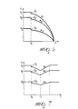
- Figure 5 instead shows the deceleration curve of the system when one introduces the initial slope in the calculation algorithm of the regulator, initial slope which is calculated by the computer 3, which provides a considerable approximation of the theoretical deceleration curve.
- a sampling circuit 5 of the sample & hold type continuously calculates and stores a reference value of the voltage on the DC bus.
- a first relay R1 is provided on the supply line of circuit 5 and interrupts the stream of signals at the time To, holding it at the last sampled value.
- a differential amplifier 6 compares the actual voltage of the DC bus with the last value sampled from circuit 5.
- the error signal in output from amplifier 6 is sent to a closed-loop regulator 7 of the PID type, that is to say, of the type that has a proportional, integral, and derivative action, which determines a calculation algorithm for control.
- the signal in output from computer 3 is held by a third relay R3 at the time To and eliminates integral forcing on the PID regulator.
- the PID automatically regulates the deceleration so that the kinetic energy recovered by the combination of the flywheel masses is neither greater nor smaller than the energy that is sufficient to supply all the devices of the machine, maintaining the energy balance and keeping the voltage of the supply bus L constant.
- the PID calculates, a reference value, or "speed set point", for each device, so as to detect the average absorption with respect to this value. This leads to an initial speed step S1, S2, and S3, shown in Figures 6 and 7, whose size depends on the various absorptions and on the respective flywheel masses.
- the output signal from the PID is constituted by a number between 1 and 0 and is proportional to the actual value of the speed during deceleration. This signal is held by a third relay R3 and sent outside unit 1.
- the output signal from the PID can be used to regulate the various drives: for example, it can be sent to multipliers X1, X2, and X3 associated with each converter C1, C2, and C3.
- the values of the speed set points V1, V2, and V3 sampled last by three sample & hold circuits 8, 9, and 10 are held by respective relays R4, R5, and R6 and are multiplied by multipliers X1, X2, and X3 by the numeric signal computed by the PID regulator and held by relay R3.
- flywheel masses m1, m2, and m3 have a certain inertia that tends to keep them in motion.
- part of the kinetic energy of masses m1, m2, and m3 is transferred to motors M1, M2, and M3, which act as generators.
- the amount of kinetic energy converted by the motors into electric power is distributed within the system, which therefore requires no external source for the time during which the power failure occurs.
- converters C1, C2, and C3 regulate the voltage and distribute it proportionally to all the motors of the individual devices of the machine, providing uniform deceleration.
- control method according to the invention includes the following steps:
- the logic system of unit 1 is of the digital type.
- communications between the unit and the converters can occur by an RS485 serial port, but it can also be different without modifying the inventive concept.
Landscapes
- Engineering & Computer Science (AREA)
- Power Engineering (AREA)
- Control Of Multiple Motors (AREA)
Claims (15)
- Verfahren zur Gleichlaufsteuerung einer komplexen Maschine bei Fehlern oder Ausfällen im Stromversorgungsnetz, wobei die Maschine eine Mehrzahl von Antrieben (A1, A2, A3) hat, deren jeweilige Elektromotoren (M1, M2, M3) durch Konverter (C1, C2, C3) versorgt werden, welche an eine Stromversorgungsleitung (L) angeschlossen sind, und wobei jeder Antrieb eine Schwungmasse (m1, m2, m3) bekannter Größe und Geschwindigkeit (V1, V2, V3) hat, welche mit derjenigen der anderen Vorrichtungen synchronisiert ist, um dadurch die Regelmäßigkeit des Betriebs der Maschine im Dauerzustand zu gewährleisten, wobei dieses Verfahren die folgenden Schritte vor einem Netzausfall umfaßt:wobei die folgenden Schritte unmittelbar nach dem Netzausfall durchgeführt werden:a) Erkennen eines Netzrauschens und Erfassen der Dauer dieses Rauschens;b) Berechnen der Anfangsgeschvindigkeit (V1, V2, V3), um die mittlere Adsorption der gesamten Maschine aufzuheben;c) Abtasten und Speichern der Netzspannung;gekennzeichnet durch die folgenden Schritte vor einem aktuellen Netzausfall:d) Berechnen der Größe der Anfangsgeschwindigkeit, die zum Aufheben der mittleren Adsorption errechnen wurde;e) Vergleich der aktuellen Größe der Spannung in der Versorgungsleitung mit dem zuletzt abgetasteten Wert, um ein erstes Störsignal zu erhalten;und durch die folgenden Schritte unmittelbar nach dem aktuellen Netzausfall:Berechnen des Trägheitsmomentes einer oder mehrerer Schwungmassen (m1, m2, m3), welches signifikanter als die anderen ist;Berechnen der Anfangssteigung der optimalen Verzögerungskurve auf der Basis der signifikantesten Schwungmasse (m1, m2, m3), der entsprechenden Gewindigkeiten (V1, V2, V3) und der aufgenommenen Ströme (I1, I2, I3);wobei während der Verzögerung der Maschine die kinetische Energie der Vorrichtungen (A1, A2, A3), welche die signifikantesten Schwungmassen haben, durch die Konverter teilweise in elektrische Energie umgewandelt wird, und zwar in einer Größenordnung, die ausreicht, um beide Konverter und die elektronischen Schaltungen für Berechnung, Regelung und Steuerung der Maschine zu versorgen.Festlegen des Wertes der Anfangssteigung der Verzögerungskurve und Einführen dieses Wertes in einen Berechnungsalgorithmus;Weitergabe des ersten Störsignals in einen geschlossenen Regelkreis (7), der über den Berechnungsalgorithmus ein zweites Fehlersignal ermittelt;Weitergabe des zweiten Fehlersignals an die Geschwindigkeitskonverter (C1, C2, C3) jeder einzelnen Vorrichtung (A1, A2, A3), um deren Geschwindigkeit schrittweise zu verringern, wobei der Gleichlauf mit den anderen Vorrichtungen der Maschine beibehalten bleibt;
- Verfahren nach Anspruch 1, dadurch gekennzeichnet, daß der geschlossene Regelkreis eine PID-Schaltung ist.
- Verfahren nach Anspruch 1, dadurch gekennzeichnet, daß der geschlossene Regelkreis eine Analogschaltung mit konventionellen Bauelementen ist.
- Verfahren nach Anspruch 1, dadurch gekennzeichnet, daß der geschlossene Regelkreis aus einer Fuzzy-Schaltung besteht.
- Verfahren nach Anspruch 2, dadurch gekennzeichnet, daß das Ausgangsfehlersignal der PID-Schaltung eine numerische Größe zwischen 1 und 0 hat, welche den entsprechenden Augenblickswerten der Geschwindigkeit entspricht, die durch die Verzögerungskurve definiert sind.
- Verfahren nach Anspruch 5, dadurch gekennzeichnet, daß die Geschwindigkeit jedes Motors kontinuierlich durch einen Abtast-und Haltekreis gemessen und erfaßt wird, wobei der zuletzt erfaßte Wert mit dem numerischen Wert multipliziert wird durch einen Multiplizieroperator, der jedem Konverter zugeordnet ist.
- Verfahren nach Anspruch 1, dadurch gekennzeichnet, daß der Teil der kinetischen Energie, der durch die Konverter während der Verzögerung in elektrische Energie umgewandelt wird, ausreicht, um die Versorgungsspannung auf einem Wert zu halten, der wenigstens 10% des Nennwertes entspricht.
- Verfahren nach Anspruch 1, dadurch gekennzeichnet, daß die Versorgungsleitung für die Vorrichtungen eine Gleichstromleitung ist.
- Verfahren nach Anspruch 1, dadurch gekennzeichnet, daß die Steuer- und Regelschaltungen digitale Mikroprozessoren enthalten.
- Verfahren nach Anspruch 1, dadurch gekennzeichnet, daß die Steuer- und Regelschaltungen analoger Bauart sind.
- Verfahren nach Anspruch 1, dadurch gekennzeichnet, daß die Endgeschwindigkeit der Vorrichtungen am Ende der Verzögerung in Abhängigkeit von der effektiven Dauer des Netzausfalls größer als oder gleich Null sein kann.
- Vorrichtung zur Gleichlaufsteuerung einer komplexen Maschine bei Fehlern oder Ausfällen der elektrischen Versorgung für die Durchführung des Verfahrens nach einem der vorhergehenden Ansprüche, wobei diese Maschine eine Mehrzahl angetriebener Vorrichtungen (A1, A2, A3) für die Bewegung und Steuerung der einzelnen Komponenten aufweist und jede Vorrichtung über einen Geschwindigkeitskonverter (C1, C2, C3) mit einem Stromversorgungsbus verbunden ist, eine Schwungmasse (m1, m2, m3) bekannter Größe aufweist und im Dauerzustand eine Geschwindigkeit (V1, V2, V3) hat, welche mit derjenigen der anderen Vorrichtungen synchronisiert wird, um die Regelmäßigkeit des Betriebs der Maschine sicherzustellen, wobei die Steuervorrichtung umfaßt:dadurch gekennzeichnet, daß die Vorrichtung ferner umfaßtein System (2) zum Erkennen eines aktuellen Netzstromausfalls;Mittel zum Messen der Geschwindigkeit (V1, V2, V3) und des Stromes (I1, I2, I3) der einzelnen Vorrichtungen;eine Schaltung (5) für den Vergleich der Spannung im Stromversorgungsbus mit dem letzten Wert der Spannung, der vor dem Netzstromausfall ermittelt wurde und der geeignet ist, ein erstes Fehlersignal zu erzeugen;einen geschlossenen Regelkreis (7) zur Erzeugung des ersten Fehlersignals, um ein zweites Fehlersignal zu generieren;einen Prozessor (3) zum Errechnen der Trägheitsmomente der signifikantesten Schwungsmassen (m1, m2, m3) und der Anfangssteigung der Verzögerung in Funktion der Trägheitsmomente der signifikantesten Schwungmassen (m1, m2, m3), der entsprechenden Geschwindigkeiten (V1, V2, V3) und der aufgenommenen Ströme (I1, I2, I3) ; sowieeinen Multiplizieroperator (X1, X2, X3), der jedem Konverter (C1, C2, C3) zugeordnet ist, um die schrittweise und synchrone Verzögerung aller Vorrichtungen (A1, A2, A3) zu steuern, wobei ein Teil der kinetischen Energie der signifikantesten Schwungmassen (m1, m2, m3) in elektrische Energie für die Versorgung des Steuersystems der Vorrichtungen umgewandelt wird.
- Vorrichtung nach Anspruch 12, dadurch gekennzeichnet, daß diese einen digitalen Mikroprozessor mit einem geschlossenen PID-Regelkreis (7) aufweist.
- Vorrichtung nach Anspruch 12, dadurch gekennzeichnet, daß diese einen Abtast- und Haltekreis zum Erfassen sowohl der Netzspannung als auch der Geschwindigkeit jeder Vorrichtung aufweist, wobei die Schaltungen durch ein Signal aktiviert werden, welches durch das System zum Erkennen des aktuellen Stromausfalls in dem Augenblick erzeugt wird, in dem die Netzstromversorgung ausfällt.
- Vorrichtung nach Anspruch 14, dadurch gekennzeichnet, daß das System (2) zum Erfassen eines Stromausfalls so eingestellt ist, daß ein Rauschen erfaßt wird, das länger als 10 msec anhält.
Applications Claiming Priority (3)
| Application Number | Priority Date | Filing Date | Title |
|---|---|---|---|
| ITVI950112 | 1995-07-05 | ||
| IT95VI000112A IT1280535B1 (it) | 1995-07-05 | 1995-07-05 | Metodo ed unita' per il controllo di sincronismo di macchine complesse in caso di mancanze di alimentazione eletttrica |
| PCT/EP1996/002802 WO1997002650A1 (en) | 1995-07-05 | 1996-06-27 | Method and unit for controlling the synchronization of complex machines in case of electric power failure |
Publications (2)
| Publication Number | Publication Date |
|---|---|
| EP0836764A1 EP0836764A1 (de) | 1998-04-22 |
| EP0836764B1 true EP0836764B1 (de) | 1999-11-03 |
Family
ID=11425824
Family Applications (1)
| Application Number | Title | Priority Date | Filing Date |
|---|---|---|---|
| EP96923949A Expired - Lifetime EP0836764B1 (de) | 1995-07-05 | 1996-06-27 | Verfahren und vorrichtung zur regelung der synchronisation von komplexen maschinen im fall des ausfalls der elektrischen stromversorgung |
Country Status (5)
| Country | Link |
|---|---|
| EP (1) | EP0836764B1 (de) |
| AU (1) | AU6417596A (de) |
| DE (1) | DE69605043T2 (de) |
| IT (1) | IT1280535B1 (de) |
| WO (1) | WO1997002650A1 (de) |
Cited By (1)
| Publication number | Priority date | Publication date | Assignee | Title |
|---|---|---|---|---|
| CN102205512A (zh) * | 2010-03-29 | 2011-10-05 | 大隈株式会社 | 用于机床的控制装置 |
Families Citing this family (16)
| Publication number | Priority date | Publication date | Assignee | Title |
|---|---|---|---|---|
| JP2000078870A (ja) * | 1998-08-31 | 2000-03-14 | Murata Mach Ltd | モータ駆動システム |
| AU5882599A (en) | 1998-09-24 | 2000-04-10 | Super Dimension Ltd. | System and method for determining the location of a catheter during an intra-body medical procedure |
| FI113309B (fi) * | 2001-06-29 | 2004-03-31 | Abb Oy | Verkkokatkoshidastus |
| DE10257980B4 (de) * | 2002-01-18 | 2016-01-14 | Heidelberger Druckmaschinen Ag | Spannungsversorgungsmanagement in papierverarbeitenden Maschinen |
| US9575140B2 (en) | 2008-04-03 | 2017-02-21 | Covidien Lp | Magnetic interference detection system and method |
| EP2297673B1 (de) | 2008-06-03 | 2020-04-22 | Covidien LP | Registrationsverfahren auf merkmalbasis |
| US8218847B2 (en) | 2008-06-06 | 2012-07-10 | Superdimension, Ltd. | Hybrid registration method |
| BE1023597B1 (nl) * | 2015-11-10 | 2017-05-11 | Nv Michel Van De Wiele | Werkwijze voor het gecontroleerd tot stilstand brengen van een textielmachine en textielmachine voorzien om volgens die werkwijze tot stilstand gebracht te worden |
| US10517505B2 (en) | 2016-10-28 | 2019-12-31 | Covidien Lp | Systems, methods, and computer-readable media for optimizing an electromagnetic navigation system |
| US10751126B2 (en) | 2016-10-28 | 2020-08-25 | Covidien Lp | System and method for generating a map for electromagnetic navigation |
| US10638952B2 (en) | 2016-10-28 | 2020-05-05 | Covidien Lp | Methods, systems, and computer-readable media for calibrating an electromagnetic navigation system |
| US10615500B2 (en) | 2016-10-28 | 2020-04-07 | Covidien Lp | System and method for designing electromagnetic navigation antenna assemblies |
| US10446931B2 (en) | 2016-10-28 | 2019-10-15 | Covidien Lp | Electromagnetic navigation antenna assembly and electromagnetic navigation system including the same |
| US10722311B2 (en) | 2016-10-28 | 2020-07-28 | Covidien Lp | System and method for identifying a location and/or an orientation of an electromagnetic sensor based on a map |
| US10792106B2 (en) | 2016-10-28 | 2020-10-06 | Covidien Lp | System for calibrating an electromagnetic navigation system |
| US10418705B2 (en) | 2016-10-28 | 2019-09-17 | Covidien Lp | Electromagnetic navigation antenna assembly and electromagnetic navigation system including the same |
Family Cites Families (5)
| Publication number | Priority date | Publication date | Assignee | Title |
|---|---|---|---|---|
| DE3347113C2 (de) * | 1983-12-27 | 1986-04-10 | SKF GmbH, 8720 Schweinfurt | Spinn- oder Zwirnmaschine mit Einzelantrieb |
| JPS6139896A (ja) * | 1984-07-30 | 1986-02-26 | Toshiba Corp | 電動機群の駆動装置 |
| JPS63283498A (ja) * | 1987-05-14 | 1988-11-21 | Meidensha Electric Mfg Co Ltd | インバ−タ装置の減速停止制御装置 |
| WO1990015474A1 (fr) * | 1989-06-09 | 1990-12-13 | Hitachi, Ltd. | Unite de commande de moteur |
| DE4306307C2 (de) * | 1993-03-01 | 1997-08-14 | Siemens Ag | Verfahren zur Schadensverhütung an numerisch gesteuerten Maschinen bei Netzausfall |
-
1995
- 1995-07-05 IT IT95VI000112A patent/IT1280535B1/it active IP Right Grant
-
1996
- 1996-06-27 EP EP96923949A patent/EP0836764B1/de not_active Expired - Lifetime
- 1996-06-27 DE DE69605043T patent/DE69605043T2/de not_active Expired - Lifetime
- 1996-06-27 AU AU64175/96A patent/AU6417596A/en not_active Abandoned
- 1996-06-27 WO PCT/EP1996/002802 patent/WO1997002650A1/en not_active Ceased
Cited By (2)
| Publication number | Priority date | Publication date | Assignee | Title |
|---|---|---|---|---|
| CN102205512A (zh) * | 2010-03-29 | 2011-10-05 | 大隈株式会社 | 用于机床的控制装置 |
| CN102205512B (zh) * | 2010-03-29 | 2014-10-01 | 大隈株式会社 | 用于机床的控制装置 |
Also Published As
| Publication number | Publication date |
|---|---|
| DE69605043T2 (de) | 2000-06-29 |
| ITVI950112A1 (it) | 1997-01-05 |
| AU6417596A (en) | 1997-02-05 |
| ITVI950112A0 (it) | 1995-07-05 |
| EP0836764A1 (de) | 1998-04-22 |
| WO1997002650A1 (en) | 1997-01-23 |
| IT1280535B1 (it) | 1998-01-22 |
| DE69605043D1 (de) | 1999-12-09 |
Similar Documents
| Publication | Publication Date | Title |
|---|---|---|
| WO1997002650A1 (en) | Method and unit for controlling the synchronization of complex machines in case of electric power failure | |
| US6956339B1 (en) | Multiple hoist synchronization apparatus and method | |
| US4371823A (en) | Apparatus and method for starting textile winder synchronous motor drives | |
| JPS59201692A (ja) | 二つの非同期モ−タの加速と減速を制御するための方法および装置 | |
| US5796221A (en) | Overload detector for servo driven machines | |
| WO1990015474A1 (fr) | Unite de commande de moteur | |
| US4477761A (en) | Method of and system for minimizing current consumption of one or more A-C motors driving a variable load | |
| JPS623677B2 (de) | ||
| EP0985753A1 (de) | Motorantriebssystem | |
| EP0311106B1 (de) | Spinnmaschine | |
| US5566604A (en) | Apparatus for extracting a flexible product from a machine for fabricating same | |
| US20230318494A1 (en) | Method for connecting an electric asynchronous machine of a powertrain to an electric grid | |
| CN113556063A (zh) | 中间电路转换器的控制装置和中间电路转换器 | |
| Jeftenic et al. | Realization of rewinder with a reduced number of sensors | |
| EP0682405B1 (de) | Vorrichtung zur Regelung eines Aufzugmotors | |
| JPH03284191A (ja) | 粗紡機の停止方法 | |
| US2951192A (en) | Electric motor controllers | |
| JPH0213554A (ja) | 巻取機制御装置 | |
| JPH03178585A (ja) | 最適モータ制御方法 | |
| JPH10174489A (ja) | 巻取機制御装置 | |
| KR930000625B1 (ko) | 얀사이징 머쉰(Yarn Sizing Machine)의 구동장치 | |
| JP3050610B2 (ja) | 電源装置 | |
| JPH11267900A (ja) | サーボプレスの停止動作の監視装置 | |
| CN117375479A (zh) | 原料提升机的速度监控系统及方法 | |
| PO | Regenerative centrifuge drive |
Legal Events
| Date | Code | Title | Description |
|---|---|---|---|
| PUAI | Public reference made under article 153(3) epc to a published international application that has entered the european phase |
Free format text: ORIGINAL CODE: 0009012 |
|
| 17P | Request for examination filed |
Effective date: 19971206 |
|
| AK | Designated contracting states |
Kind code of ref document: A1 Designated state(s): CH DE FR GB IT LI |
|
| GRAG | Despatch of communication of intention to grant |
Free format text: ORIGINAL CODE: EPIDOS AGRA |
|
| 17Q | First examination report despatched |
Effective date: 19981002 |
|
| GRAG | Despatch of communication of intention to grant |
Free format text: ORIGINAL CODE: EPIDOS AGRA |
|
| GRAH | Despatch of communication of intention to grant a patent |
Free format text: ORIGINAL CODE: EPIDOS IGRA |
|
| GRAH | Despatch of communication of intention to grant a patent |
Free format text: ORIGINAL CODE: EPIDOS IGRA |
|
| GRAA | (expected) grant |
Free format text: ORIGINAL CODE: 0009210 |
|
| AK | Designated contracting states |
Kind code of ref document: B1 Designated state(s): CH DE FR GB IT LI |
|
| REG | Reference to a national code |
Ref country code: CH Ref legal event code: EP |
|
| REF | Corresponds to: |
Ref document number: 69605043 Country of ref document: DE Date of ref document: 19991209 |
|
| ITF | It: translation for a ep patent filed | ||
| REG | Reference to a national code |
Ref country code: CH Ref legal event code: NV Representative=s name: ISLER & PEDRAZZINI AG |
|
| ET | Fr: translation filed | ||
| PLBE | No opposition filed within time limit |
Free format text: ORIGINAL CODE: 0009261 |
|
| STAA | Information on the status of an ep patent application or granted ep patent |
Free format text: STATUS: NO OPPOSITION FILED WITHIN TIME LIMIT |
|
| 26N | No opposition filed | ||
| REG | Reference to a national code |
Ref country code: GB Ref legal event code: IF02 |
|
| REG | Reference to a national code |
Ref country code: CH Ref legal event code: PCAR Free format text: ISLER & PEDRAZZINI AG;POSTFACH 1772;8027 ZUERICH (CH) |
|
| PGFP | Annual fee paid to national office [announced via postgrant information from national office to epo] |
Ref country code: GB Payment date: 20070529 Year of fee payment: 12 |
|
| GBPC | Gb: european patent ceased through non-payment of renewal fee |
Effective date: 20080627 |
|
| PG25 | Lapsed in a contracting state [announced via postgrant information from national office to epo] |
Ref country code: GB Free format text: LAPSE BECAUSE OF NON-PAYMENT OF DUE FEES Effective date: 20080627 |
|
| PGFP | Annual fee paid to national office [announced via postgrant information from national office to epo] |
Ref country code: CH Payment date: 20100702 Year of fee payment: 15 |
|
| PGFP | Annual fee paid to national office [announced via postgrant information from national office to epo] |
Ref country code: IT Payment date: 20100630 Year of fee payment: 15 Ref country code: FR Payment date: 20100720 Year of fee payment: 15 Ref country code: DE Payment date: 20100804 Year of fee payment: 15 |
|
| REG | Reference to a national code |
Ref country code: CH Ref legal event code: PL |
|
| PG25 | Lapsed in a contracting state [announced via postgrant information from national office to epo] |
Ref country code: IT Free format text: LAPSE BECAUSE OF NON-PAYMENT OF DUE FEES Effective date: 20110627 |
|
| REG | Reference to a national code |
Ref country code: FR Ref legal event code: ST Effective date: 20120229 |
|
| REG | Reference to a national code |
Ref country code: DE Ref legal event code: R119 Ref document number: 69605043 Country of ref document: DE Effective date: 20120103 |
|
| PG25 | Lapsed in a contracting state [announced via postgrant information from national office to epo] |
Ref country code: DE Free format text: LAPSE BECAUSE OF NON-PAYMENT OF DUE FEES Effective date: 20120103 Ref country code: LI Free format text: LAPSE BECAUSE OF NON-PAYMENT OF DUE FEES Effective date: 20110630 Ref country code: FR Free format text: LAPSE BECAUSE OF NON-PAYMENT OF DUE FEES Effective date: 20110630 Ref country code: CH Free format text: LAPSE BECAUSE OF NON-PAYMENT OF DUE FEES Effective date: 20110630 |