EP0836809B1 - Verfahren zur Kontrolle der gefüllten Enden von Tabaksartikeln - Google Patents
Verfahren zur Kontrolle der gefüllten Enden von Tabaksartikeln Download PDFInfo
- Publication number
- EP0836809B1 EP0836809B1 EP97117962A EP97117962A EP0836809B1 EP 0836809 B1 EP0836809 B1 EP 0836809B1 EP 97117962 A EP97117962 A EP 97117962A EP 97117962 A EP97117962 A EP 97117962A EP 0836809 B1 EP0836809 B1 EP 0836809B1
- Authority
- EP
- European Patent Office
- Prior art keywords
- photosensors
- article
- value
- emitted
- foregoing
- Prior art date
- Legal status (The legal status is an assumption and is not a legal conclusion. Google has not performed a legal analysis and makes no representation as to the accuracy of the status listed.)
- Expired - Lifetime
Links
- 238000000034 method Methods 0.000 title claims description 28
- 241000208125 Nicotiana Species 0.000 title claims description 8
- 235000002637 Nicotiana tabacum Nutrition 0.000 title claims description 8
- 230000005855 radiation Effects 0.000 claims description 10
- 230000005670 electromagnetic radiation Effects 0.000 claims description 7
- 238000005259 measurement Methods 0.000 claims description 2
- 230000000149 penetrating effect Effects 0.000 claims description 2
- 235000019504 cigarettes Nutrition 0.000 description 47
- 230000003287 optical effect Effects 0.000 description 8
- 230000035945 sensitivity Effects 0.000 description 2
- 230000000295 complement effect Effects 0.000 description 1
- 238000001514 detection method Methods 0.000 description 1
- 230000001939 inductive effect Effects 0.000 description 1
- 238000002329 infrared spectrum Methods 0.000 description 1
- 238000007689 inspection Methods 0.000 description 1
- 230000000717 retained effect Effects 0.000 description 1
Images


Classifications
-
- B—PERFORMING OPERATIONS; TRANSPORTING
- B65—CONVEYING; PACKING; STORING; HANDLING THIN OR FILAMENTARY MATERIAL
- B65B—MACHINES, APPARATUS OR DEVICES FOR, OR METHODS OF, PACKAGING ARTICLES OR MATERIALS; UNPACKING
- B65B19/00—Packaging rod-shaped or tubular articles susceptible to damage by abrasion or pressure, e.g. cigarettes, cigars, macaroni, spaghetti, drinking straws or welding electrodes
- B65B19/28—Control devices for cigarette or cigar packaging machines
- B65B19/30—Control devices for cigarette or cigar packaging machines responsive to presence of faulty articles, e.g. incorrectly filled cigarettes
-
- A—HUMAN NECESSITIES
- A24—TOBACCO; CIGARS; CIGARETTES; SIMULATED SMOKING DEVICES; SMOKERS' REQUISITES
- A24C—MACHINES FOR MAKING CIGARS OR CIGARETTES
- A24C5/00—Making cigarettes; Making tipping materials for, or attaching filters or mouthpieces to, cigars or cigarettes
- A24C5/32—Separating, ordering, counting or examining cigarettes; Regulating the feeding of tobacco according to rod or cigarette condition
- A24C5/34—Examining cigarettes or the rod, e.g. for regulating the feeding of tobacco; Removing defective cigarettes
- A24C5/3412—Examining cigarettes or the rod, e.g. for regulating the feeding of tobacco; Removing defective cigarettes by means of light, radiation or electrostatic fields
-
- G—PHYSICS
- G01—MEASURING; TESTING
- G01N—INVESTIGATING OR ANALYSING MATERIALS BY DETERMINING THEIR CHEMICAL OR PHYSICAL PROPERTIES
- G01N21/00—Investigating or analysing materials by the use of optical means, i.e. using sub-millimetre waves, infrared, visible or ultraviolet light
- G01N21/84—Systems specially adapted for particular applications
- G01N21/88—Investigating the presence of flaws or contamination
- G01N21/95—Investigating the presence of flaws or contamination characterised by the material or shape of the object to be examined
- G01N21/952—Inspecting the exterior surface of cylindrical bodies or wires
Definitions
- the present invention relates to a method of controlling the endfill of tobacco articles.
- the present invention relates to a method of controlling the endfill of cigarettes, to which the following description refers purely by way of example.
- the endfill of cigarettes is normally controlled, as the cigarettes are conveyed side by side, by sensors for determining the presence of tobacco in a given end portion of each cigarette.
- the sensors may be capacitive, optical, inductive, etc., and are located along a path of the cigarettes, close to one end of the cigarettes. As the ends of the cigarettes are not normally aligned perfectly and are therefore variously positioned with respect to the sensors, the sensor readings are affected by the distance between the sensors and the ends being controlled.
- Another known solution is to determine the position of the ends of the cigarettes by means of a first optical sensor, as a succession of side by side cigarettes is fed along a given path; subject one end of each cigarette frontally to a beam of electromagnetic radiation parallel to the axis of the cigarette; and, finally, determine, by means of a second sensor, the radiation reflected by the surface of said end to generate a corresponding signal characteristic of the endfill of each cigarette.
- the reading of the second sensor is corrected, taking into account the distance between the end of each cigarette and the second sensor, by means of a mathematical algorithm based on a physical model or test data; and a reject signal is generated in the event the characteristic signal is below a given threshold value.
- the above front control method fails to determine any cavities beneath an apparently satisfactory end surface, and involves mathematically correlating heterogeneous quantities such as the distance between the sensor and the ends of the cigarettes, and the quantity of light reflected.
- a method according to the preamble of claim 1 is disclosed in EP-A-0 434 457.
- a method of controlling the endfill of an end of elongated tobacco articles comprising the steps of directing at least one collimated beam of electromagnetic radiation, having a given emission intensity, on to a series of photosensors aligned in a first direction parallel to said axis of each article and emitting a signal proportional to an incident radiation intensity; the beam being so directed as to be partially intercepted by said end of the article; and the method being characterized by also comprising a reject step wherein the signal emitted by photosensors struck by the portion of the beam not intercepted by said end is rejected by means of a threshold measurement; and a comparing step wherein the signal emitted by photosensors struck by the portion of the beam intercepted by the article and penetrating the article is compared with a range of limit values characteristic of the end fill and a function of said emission intensity, to determine acceptability of the article.
- Number 1 in Figure 1 indicates a device for controlling the endfill of cigarettes 2, each having a longitudinal axis 3.
- cigarettes 2 are fed side by side in a traveling direction 4 crosswise to axis 3 by a conveying member 5, by which cigarettes 2 are retained inside respective seats 6 by known suction means (not shown).
- each cigarette 2 comprises a paper wrapping 7 enclosing shredded tobacco 8; a free first end 9; and a second end 10 normally comprising a filter 11.
- the first end 9 of each cigarette 2 projects from conveying member 5 by a length varying between a maximum and a minimum value; and the distance L between said maximum and minimum values represents the width of a path P extending in direction 4 and along which the respective ends 9 of cigarettes 2 lie.
- control device 1 comprises an optical assembly 12, in turn comprising an emitter 13 for emitting a beam 14 of electromagnetic radiation, an optical collimating device 15 for forming a collimated beam 16, and a receiving assembly 17.
- receiving assembly 17 comprises a plate 18 supporting a series of photosensors 19 equally spaced in a direction parallel to axis 3, and each for emitting a signal proportional to the intensity of electromagnetic energy impinging on photosensor 19 itself.
- Control device 1 also comprises an apparatus 20 for controlling emitter 13 and processing the signals emitted by photosensors 19, and which in turn comprises an amplifier 21 for amplifying the signals received from photosensors 19.
- Amplifier 21 is connected to a drive device 22 for driving emitter 13, and to a synchronizing/memorizing device 23 receiving both position signals relative to seats 6 on conveying member 5, and the signals of photosensors 19 amplified by amplifier 21; and synchronizing/memorizing device 23 is connected to an analog/digital converter 24, which transmits digitized signals to a processing unit 25 for processing a reject signal on the basis of threshold values.
- drive device 22 activates emitter 13 to emit a beam 16, which, when collimated, is of a width at least equal to width L of path P, and extends between optical collimating device 15 and plate 18.
- seat 6 contains a cigarette 2, beam 16, or a portion of it, impinges on end 9 of cigarette 2, and the collimated beam 16 is divided by end 9 into a number of components, of which will be considered, for the purpose of the control in question, a first component 16a whose energy content is unaffected by end 9, and a second component 16b which penetrates end 9 to reach plate 18.
- the extension, parallel to axis 3, of each component 16a, 16b depends on the position of cigarette 2, in the sense that, the further cigarette 2 projects from conveying member 5, the smaller is the extension of component 16a, which is complementary to the extension of component 16b.
- Components 16a and 16b define on plate 18 a first group 19a and a second group 19b of photosensors 19.
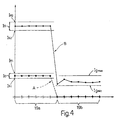
- the Figure 4 graph shows, along the Y axis, the electromagnetic energy intensity values involved; along the X axis, the position of each photosensor 19 with respect to a fixed reference point and in a direction parallel to axis 3; a first curve A showing the received energy intensity with respect to an energy intensity Ie1 emitted by emitter 13; and a second curve B showing the received energy intensity with respect to an energy intensity Ie2 emitted by emitter 13.
- each curve A and B shows a sharp variation in received energy intensity values Ie, which provides for distinguishing first group 19a from second group 19b of photosensors 19. Given the position of photosensors 19 along plate 18, it is therefore possible to determine the position of cigarette 2 with respect to plate 18 and/or to path P and/or to any other reference point.
- the electromagnetic energy intensity values detected by sensors 19 in first group 19a substantially correspond with value Ie of the electromagnetic energy intensity emitted by emitter 13 and are equal to one another; whereas the electromagnetic energy values detected by sensors 19 in second group 19b are well below the emitted energy values, due to part of the energy being absorbed, partly refracted and partly reflected, and only a portion of the energy being transmitted through end 9 of cigarette 2.
- the signals emitted by photosensors 19 in group 19b are characteristic of the endfill of end 9, and may assume different values due to nonuniformity of the filling along axis 3 of cigarette 2.
- each photosensor 19 is compared with a limit value Is equal to emitted energy intensity value Ie minus a value Io comprising a first component corresponding to the quantity of energy subtracted by optical collimating device 15, and a second component corresponding to a safety value.
- value Is is slightly below value Ie of the energy intensity emitted by emitter 13.
- Figure 4 shows the respective emitted energy intensity values Ie1, Ie2 and respective values Is1, Is2.
- the signals emitted by photosensors 19 in group 19a are rejected, whereas each of the signals emitted by photosensors 19 in group 19b, if other than zero, is compared with a range of threshold values Igmin and Igmax characteristic of the endfill, to determine the acceptability of the endfill of each end 9.
- Endfill threshold values Igmin and Igmax may be established experimentally for different types of shredded tobacco 8, for different types of wrappings 7, and for different emitted electromagnetic intensity values, or may conveniently be established by defining a range about a mean value detected by photosensors 19 in second group 19b relative to a given emission intensity Ie and a large number of cigarettes.
- Figure 4 shows threshold values Igmin and Igmax relative to emitted energy intensity value Ie2.
- the position of cigarettes 2 in no way affects detection of the endfill, by only the values transmitted through ends 9 being compared with the Igmin-Igmax range, with no need to correlate a cigarette 2 position signal with a characteristic endfill signal by means of special algorithms.
- the position of cigarettes 2 with respect, for example, to a photosensor 19 located at the end of plate 18 may be determined by simply subtracting from the segment defined by the two photosensors 19 at opposite ends of plate 18 the sum of the distances between the adjacent photosensors 19 emitting respective signals greater than or equal to the respective characteristic position value Is.
- a single series of signals emitted by photosensors 19 therefore provides for obtaining information relative to both the position of cigarettes 2 and the endfill of ends 9 of cigarettes 2.
- drive device 22 activates emitter 13 so as to initially emit a low energy intensity Ie, and, depending on the signals emitted by photosensors 19, increases emitted energy intensity Ie if an end 9 of a cigarette 2 is detected, and cuts off emission in the absence of end 9.
- low energy intensity Ie1 corresponds to curve A in Figure 4, in which the intensity of the signals emitted by photosensors 19 in group 19b equals or is close to zero, due to the emitted energy Ie1 being practically entirely reflected or absorbed by end 9 of cigarette 2.
- this first phase it is possible to determine the position of end 9 and distinguish first group 19a from second group 19b of photosensors 19; following which, emitted energy Ie is increased to a value Ie2 to obtain signals of other than zero from photosensors 19 in group 19b.
- the control cycle of each cigarette 2 provides for emitting an electromagnetic energy intensity Ie ranging between a minimum initial value and a maximum value.
- the maximum energy intensity value be limited to the minimum required to obtain signals of other than zero from photosensors 19 in group 19b, in that high electromagnetic radiation intensities impinging on photosensors 19 may possibly distort the signals emitted by the photosensors.
- assembly 12 comprises a first emitter 26 and a second emitter 27 located side by side in the traveling direction 4 of cigarettes 2, and generating respective electromagnet radiation beams 28 and 29 through respective optical collimation devices 30 and 31 to form respective collimated beams 32 and 33; and, similarly, plate 18 is fitted with two rows 34 and 35 of photosensors 19, located side by side and for intercepting respective collimated beams 32 and 33.
- emitters 26 and 27 generate respective beams 28 and 29 of different intensities, the first emitter 26 operating at minimum intensity, and the second emitter 27 at maximum intensity.
- control cycle is performed using two collimated beams 32 and 33; a first beam 32 being detected by a first row 34 of photosensors 19 of relatively high sensitivity; and a second beam 33 being detected by a second row 35 of photosensors 19 of relatively low sensitivity.
- Two collimated beams 32 and 33 may be used to advantage for controlling the endfill of particular cigarettes 2 of low radiation transparency and requiring the use of particularly high radiation intensities, which may blind photosensors 19 and, on account of the hysteresis of photosensors 19, slow down the control cycle, thus requiring a reduction in the traveling speed of cigarettes 2 in direction 4.
Landscapes
- Health & Medical Sciences (AREA)
- General Health & Medical Sciences (AREA)
- General Physics & Mathematics (AREA)
- Immunology (AREA)
- Life Sciences & Earth Sciences (AREA)
- Chemical & Material Sciences (AREA)
- Analytical Chemistry (AREA)
- Biochemistry (AREA)
- Toxicology (AREA)
- Physics & Mathematics (AREA)
- Pathology (AREA)
- Engineering & Computer Science (AREA)
- Mechanical Engineering (AREA)
- Manufacturing Of Cigar And Cigarette Tobacco (AREA)
- Length Measuring Devices By Optical Means (AREA)
- Investigating Or Analyzing Non-Biological Materials By The Use Of Chemical Means (AREA)
Claims (12)
- Verfahren zum Kontrollieren der Endfüllung eines Endes (9) langgestreckter Tabakartikel (2), die jeweils eine Längsachse (3) aufweisen; wobei das Verfahren die Schritte des Richtens wenigstens eines gebündelten Strahls (16; 32, 33) elektromagnetischer Strahlung mit einer gegebenen Emissionsintensität (Ie) auf einen Photosensor (19); des Aussendens eines Signals, das proportional zu einer einfallenden Strahlungsintensität ist; und einen Vergleichsschritt umfaßt, bei dem das Signal, das von dem Photosensor (19) ausgesendet wird, der von dem Strahl (16; 32, 33) getroffen wird, der vom Artikel (2) abgefangen wird und den Artikel (2) durchdringt, mit einem Bereich von Grenzwerten (Igmin, Igmax) verglichen wird, die für die Endfüllung und eine Funktion der Emissionsintensität (Ie) charakteristisch sind, um die Annehmbarkeit des Artikels (2) zu ermitteln; dadurch gekennzeichnet, daß der Photosensor (19) eine Reihe von Photosensoren (19) umfaßt, die in einer ersten Richtung parallel zur Achse (3) des jeweiligen Artikels (2) ausgerichtet sind; und der Strahl (16; 32, 33) so gerichtet ist, daß er teilweise vom Ende (9) des Artikels (2) abgefangen wird; und das Verfahren ferner einen Zurückweisungsschritt umfaßt, bei dem das Signal, das von den Photosensoren (19) ausgesendet wird, die von dem Teil des Strahls (16; 32, 33) getroffen werden, der nicht vom Ende abgefangen wird, mittels einer Schwellenmessung zurückgewiesen wird.
- Verfahren nach Anspruch 1, dadurch gekennzeichnet, daß es ferner die Schritte des Zuführens einer Folge von Artikeln (2) Seite an Seite in einer Richtung (4) quer zur ersten Richtung umfaßt, so daß das Ende (9) jedes Artikels (2) längs einer Bahn (P) mit einer gegebenen Breite (L) gehalten wird und sich durch den Strahl (16; 32, 33) erstreckt, der eine in der ersten Richtung gemessene Breite wenigstens gleich der gegebenen Breite (L) aufweist.
- Verfahren nach Anspruch 2, dadurch gekennzeichnet, daß die Bahn (P) zwei gegenüberliegende Längskanten parallel zur zweiten Richtung (4) umfaßt; der Strahl (16; 32, 33) und die Reihe von Photosensoren (19) sich in der ersten Richtung wenigstens über die gesamte Breite (L) der Bahn (P) zwischen den zwei Kanten erstrecken.
- Verfahren nach irgendeinem der vorangehenden Ansprüche 1 bis 3, dadurch gekennzeichnet, daß der Strahl (16; 32, 33) in einer dritten Richtung im wesentlichen senkrecht zur ersten und zur zweiten Richtung (4) ausgerichtet ist.
- Verfahren nach irgendeinem der vorangehenden Ansprüche 1 bis 4, dadurch gekennzeichnet, daß der Zurückweisungsschritt die Unterschritte des Vergleichens des vom jeweiligen Photosensor (19) ausgesendeten Signals mit einem Grenzwert (Is), der proportional ist zur Emissionsintensität (Ie) minus einem Wert (Io), der eine erste Komponente proportional zu einer dispergierten Energie und eine zweite Komponente entsprechend einem Sicherheitswert umfaßt; und des Ermittelns, ob jedes Signals unterhalb des Grenzwerts (Is) innerhalb des Bereiches der Grenzwerte (Igmin, Igmax) liegt, umfaßt.
- Verfahren nach irgendeinem der vorangehenden Ansprüche 1 bis 5, dadurch gekennzeichnet, daß die elektromagnetische Strahlung von wenigstens einem Emitter (13; 26, 27) ausgesendet wird; und die Emissionsintensität (Ie) zwischen einem anfänglichen minimalen Intensitätswert (Ie1) und einem maximalen Intensitätswert (Ie2) verändert wird.
- Verfahren nach Anspruch 6, dadurch gekennzeichnet, daß die Strahlung mit minimaler Intensität (Ie1) und die Strahlung mit maximaler Intensität (Ie2) jeweils von einem ersten (26) und einem zweiten (27) Emitter ausgesendet werden, um entsprechend einen ersten (28) und einen zweiten (29) Strahl auszusenden.
- Verfahren nach Anspruch 7, dadurch gekennzeichnet, daß der erste und der zweite Strahl (28, 29) jeweils von einer ersten (34) und einer zweiten (35) Reihe von Photodetektoren (19) abgefangen werden.
- Verfahren nach irgendeinem der Ansprüche 5 bis 8, gekennzeichnet durch den Schritt des Ermittelns der Position des Artikels (2) bezüglich eines ersten End-Photosensors (19) in der Reihe von Photosensoren (19) durch Ermitteln der Differenz zwischen einem ersten Abstand gleich der Länge der Reihe von Photosensoren (19) und einem Abstand gleich der Summe der Distanzen zwischen den benachbarten Photosensoren (19), die entsprechende Signale aussenden, die größer oder gleich dem Grenzwert (Is) sind.
- Verfahren nach irgendeinem der vorangehenden Ansprüche 5 bis 9, gekennzeichnet durch den weiteren Schritt des Aussendens eines Signals, daß das Vorhandensein des Artikels (2) anzeigt, wenn die von allen Photosensoren (19) ausgesendeten Signale größer oder gleich dem Grenzwert (Is) sind.
- Verfahren nach irgendeinem der vorangehenden Ansprüche 1 bis 10, dadurch gekennzeichnet, daß die elektromagnetische Strahlung Infrarotstrahlung ist.
- Verfahren nach irgendeinem der vorangehenden Ansprüche 5 bis 11, gekennzeichnet durch den weiteren Schritt des Erzeugens eines Zurückweisungssignals, wenn der Wert des von dem wenigstens einen Photosensor (19) ausgesendeten Signals unter dem Grenzwert (Is) und außerhalb des Bereichs der Grenzwerte (Igmin, Igmax) liegt.
Applications Claiming Priority (2)
| Application Number | Priority Date | Filing Date | Title |
|---|---|---|---|
| IT96BO000522A IT1286264B1 (it) | 1996-10-18 | 1996-10-18 | Metodo di controllo del grado di riempimento di estremita' di articoli da fumo |
| ITBO960522 | 1996-10-18 |
Publications (2)
| Publication Number | Publication Date |
|---|---|
| EP0836809A1 EP0836809A1 (de) | 1998-04-22 |
| EP0836809B1 true EP0836809B1 (de) | 2001-05-30 |
Family
ID=11341655
Family Applications (1)
| Application Number | Title | Priority Date | Filing Date |
|---|---|---|---|
| EP97117962A Expired - Lifetime EP0836809B1 (de) | 1996-10-18 | 1997-10-16 | Verfahren zur Kontrolle der gefüllten Enden von Tabaksartikeln |
Country Status (5)
| Country | Link |
|---|---|
| US (1) | US5978079A (de) |
| EP (1) | EP0836809B1 (de) |
| JP (1) | JP3946840B2 (de) |
| DE (1) | DE69705009T2 (de) |
| IT (1) | IT1286264B1 (de) |
Families Citing this family (6)
| Publication number | Priority date | Publication date | Assignee | Title |
|---|---|---|---|---|
| DE102009017962A1 (de) * | 2009-04-21 | 2010-11-04 | Hauni Maschinenbau Ag | Verfahren und Vorrichtung zur Überprüfung der Qualität von mit Kapseln versehenen Filterstäben |
| WO2011114439A1 (ja) * | 2010-03-16 | 2011-09-22 | 日本たばこ産業株式会社 | シガレット検査装置 |
| DE102014213244A1 (de) * | 2014-07-08 | 2016-01-14 | Hauni Maschinenbau Ag | Prüfung von stabförmigen Artikeln, insbesondere Filterzigaretten |
| WO2016027350A1 (ja) * | 2014-08-21 | 2016-02-25 | 日本たばこ産業株式会社 | カプセル検査装置 |
| PL227616B1 (pl) * | 2014-09-12 | 2018-01-31 | International Tobacco Machinery Poland Spólka Z Ograniczona Odpowiedzialnoscia | Urządzenie pomiarowe i sposób pomiaru prętopodobnych artykułów wielosegmentowych przemysłu tytoniowego |
| IT202000021271A1 (it) * | 2020-09-09 | 2022-03-09 | Gd Spa | Dispositivo di controllo di articoli da fumo |
Family Cites Families (14)
| Publication number | Priority date | Publication date | Assignee | Title |
|---|---|---|---|---|
| GB1388189A (en) * | 1972-06-29 | 1975-03-26 | Gallaher Ltd | Optical inspection apparatus |
| IT1010706B (it) * | 1974-03-22 | 1977-01-20 | Amf Sasib | Procedimento e dispositivo per il controllo ottico del grado di riem pimento delle teste delle sigarette |
| IT1033891B (it) * | 1975-06-03 | 1979-08-10 | Amf Sasib | Dispositivo ottico per il controllo del grado di riempimento delle teste delle sigarette |
| DE2653298A1 (de) * | 1975-12-01 | 1977-06-02 | Molins Ltd | Pruefvorrichtung zum pruefen der enden von zigaretten |
| IT1176988B (it) * | 1983-11-02 | 1987-08-26 | Hauni Werke Koerber & Co Kg | Dispositivo per controllare otticamente sigarette |
| DE3638519A1 (de) * | 1986-11-11 | 1988-05-19 | Focke & Co | Verfahren und vorrichtung zum ueberpruefen/aussondern von zigaretten |
| IT1219503B (it) * | 1987-03-17 | 1990-05-18 | Molins Plc | Apparecchio per separare sigarette difettose in una macchina per la fabbricazione di sigarette |
| US5223915A (en) * | 1989-01-13 | 1993-06-29 | G.D. Societa' Per Azioni | Cigarette end group inspection system |
| US5010904A (en) * | 1989-12-21 | 1991-04-30 | R. J. Reynolds Tobacco Company | Method and apparatus for detecting loose ends of cigarettes |
| JP2756386B2 (ja) * | 1991-12-27 | 1998-05-25 | 日本たばこ産業株式会社 | 円筒形物体の外観検査装置 |
| EP0553699A1 (de) * | 1992-01-30 | 1993-08-04 | Hauni Maschinenbau Aktiengesellschaft | Prüfanordnung zum Prüfen der Enden von Zigaretten |
| US5588068A (en) * | 1992-12-04 | 1996-12-24 | Philip Morris Incorporated | Methods and apparatus for inspecting the appearance of substantially circular objects |
| IT1263446B (it) * | 1993-06-28 | 1996-08-05 | Gd Spa | Metodo per il controllo ottico per il riempimento di sigarette. |
| DE19523273A1 (de) * | 1995-06-27 | 1997-01-09 | Hauni Maschinenbau Ag | Verfahren und Anordnung zum Messen des Durchmessers eines stabförmigen Artikels der tabakverarbeitenden Industrie |
-
1996
- 1996-10-18 IT IT96BO000522A patent/IT1286264B1/it active IP Right Grant
-
1997
- 1997-10-16 DE DE69705009T patent/DE69705009T2/de not_active Expired - Lifetime
- 1997-10-16 EP EP97117962A patent/EP0836809B1/de not_active Expired - Lifetime
- 1997-10-17 US US08/953,207 patent/US5978079A/en not_active Expired - Fee Related
- 1997-10-20 JP JP28742397A patent/JP3946840B2/ja not_active Expired - Fee Related
Also Published As
| Publication number | Publication date |
|---|---|
| EP0836809A1 (de) | 1998-04-22 |
| US5978079A (en) | 1999-11-02 |
| IT1286264B1 (it) | 1998-07-08 |
| DE69705009D1 (de) | 2001-07-05 |
| ITBO960522A1 (it) | 1998-04-18 |
| JP3946840B2 (ja) | 2007-07-18 |
| ITBO960522A0 (it) | 1996-10-18 |
| JPH10210963A (ja) | 1998-08-11 |
| DE69705009T2 (de) | 2002-01-10 |
Similar Documents
| Publication | Publication Date | Title |
|---|---|---|
| US7176696B2 (en) | Method of detecting and eliminating foreign bodies in a flow of tobacco | |
| US5406376A (en) | Apparatus for testing end portions of rod-shaped articles of the tobacco processing industry | |
| EP0630586B1 (de) | Optische Prüfvorrichtung für die Füllung von Zigaretten | |
| JP2005512586A (ja) | 多重セグメントフィルターの特性を測定するための装置、およびシステム、並びに、この測定のための方法 | |
| US6521905B1 (en) | Method and device for detecting the position of a transparent moving conveyor belt | |
| EP0836809B1 (de) | Verfahren zur Kontrolle der gefüllten Enden von Tabaksartikeln | |
| US5502312A (en) | Double document detection system having dectector calibration | |
| NL8200770A (nl) | Inrichting voor het transporteren en controleren van groepen sigaretten. | |
| EP0848246B1 (de) | Verfahren zur Messung der Intensität eines einen Körper durchdringenden Strahlenbündel | |
| GB2176598A (en) | Method and apparatus for optically testing the ends of rod-shaped articles of the tobacco processing industry | |
| KR100338489B1 (ko) | 동전판별장치 | |
| EP0370231A1 (de) | Optische Einrichtung für die Prüfung des Endes von Zigaretten | |
| CN100361164C (zh) | 自动交易机双张薄片检测器 | |
| JP3723006B2 (ja) | 端面検出装置 | |
| US5581354A (en) | Method and device for thickness assessment | |
| US5212539A (en) | Apparatus for determining at least one size parameter of an object whether it is moving or at rest | |
| CA1120128A (en) | Automatic wane detector | |
| KR100493982B1 (ko) | 개선된 잡음 허용 범위를 갖는 검출 시스템 | |
| US7605927B2 (en) | Apparatus for optically determining the profile and/or upper surface properties of flat workpieces in a wide belt abrading machine | |
| US6878103B2 (en) | Controlling cuts in an inner liner for a group of cigarettes | |
| WO2002045214A3 (en) | System and method for optically sensing motion of objects | |
| CS232741B2 (en) | Method of cigarettes' ends filling degree determination and equipment for execution of this method | |
| CN101090645A (zh) | 点燃系统 | |
| KR200171363Y1 (ko) | 웨이퍼 절삭기의 절삭날 파손 검출장치 | |
| JP2008532025A (ja) | 製品の縁を光学的に検出するためのセンサ・アセンブリ、および幅測定方法 |
Legal Events
| Date | Code | Title | Description |
|---|---|---|---|
| PUAI | Public reference made under article 153(3) epc to a published international application that has entered the european phase |
Free format text: ORIGINAL CODE: 0009012 |
|
| AK | Designated contracting states |
Kind code of ref document: A1 Designated state(s): DE FR GB IT |
|
| AX | Request for extension of the european patent |
Free format text: AL;LT;LV;RO;SI |
|
| 17P | Request for examination filed |
Effective date: 19981002 |
|
| AKX | Designation fees paid |
Free format text: DE FR GB IT |
|
| RBV | Designated contracting states (corrected) |
Designated state(s): DE FR GB IT |
|
| GRAG | Despatch of communication of intention to grant |
Free format text: ORIGINAL CODE: EPIDOS AGRA |
|
| 17Q | First examination report despatched |
Effective date: 20000905 |
|
| GRAG | Despatch of communication of intention to grant |
Free format text: ORIGINAL CODE: EPIDOS AGRA |
|
| GRAH | Despatch of communication of intention to grant a patent |
Free format text: ORIGINAL CODE: EPIDOS IGRA |
|
| GRAH | Despatch of communication of intention to grant a patent |
Free format text: ORIGINAL CODE: EPIDOS IGRA |
|
| GRAA | (expected) grant |
Free format text: ORIGINAL CODE: 0009210 |
|
| AK | Designated contracting states |
Kind code of ref document: B1 Designated state(s): DE FR GB IT |
|
| REF | Corresponds to: |
Ref document number: 69705009 Country of ref document: DE Date of ref document: 20010705 |
|
| ET | Fr: translation filed | ||
| ITF | It: translation for a ep patent filed | ||
| REG | Reference to a national code |
Ref country code: GB Ref legal event code: IF02 |
|
| PLBE | No opposition filed within time limit |
Free format text: ORIGINAL CODE: 0009261 |
|
| STAA | Information on the status of an ep patent application or granted ep patent |
Free format text: STATUS: NO OPPOSITION FILED WITHIN TIME LIMIT |
|
| 26N | No opposition filed | ||
| PGFP | Annual fee paid to national office [announced via postgrant information from national office to epo] |
Ref country code: IT Payment date: 20061031 Year of fee payment: 10 |
|
| PG25 | Lapsed in a contracting state [announced via postgrant information from national office to epo] |
Ref country code: IT Free format text: LAPSE BECAUSE OF NON-PAYMENT OF DUE FEES Effective date: 20071016 |
|
| PGFP | Annual fee paid to national office [announced via postgrant information from national office to epo] |
Ref country code: DE Payment date: 20091028 Year of fee payment: 13 |
|
| PGFP | Annual fee paid to national office [announced via postgrant information from national office to epo] |
Ref country code: GB Payment date: 20091026 Year of fee payment: 13 Ref country code: FR Payment date: 20091029 Year of fee payment: 13 |
|
| GBPC | Gb: european patent ceased through non-payment of renewal fee |
Effective date: 20101016 |
|
| PG25 | Lapsed in a contracting state [announced via postgrant information from national office to epo] |
Ref country code: FR Free format text: LAPSE BECAUSE OF NON-PAYMENT OF DUE FEES Effective date: 20101102 |
|
| REG | Reference to a national code |
Ref country code: FR Ref legal event code: ST Effective date: 20110630 |
|
| PG25 | Lapsed in a contracting state [announced via postgrant information from national office to epo] |
Ref country code: GB Free format text: LAPSE BECAUSE OF NON-PAYMENT OF DUE FEES Effective date: 20101016 |
|
| REG | Reference to a national code |
Ref country code: DE Ref legal event code: R119 Ref document number: 69705009 Country of ref document: DE Effective date: 20110502 |
|
| PG25 | Lapsed in a contracting state [announced via postgrant information from national office to epo] |
Ref country code: DE Free format text: LAPSE BECAUSE OF NON-PAYMENT OF DUE FEES Effective date: 20110502 |