EP0837241A2 - Machine à piston axiaux comportant un disque de commande adjustable - Google Patents
Machine à piston axiaux comportant un disque de commande adjustable Download PDFInfo
- Publication number
- EP0837241A2 EP0837241A2 EP97117281A EP97117281A EP0837241A2 EP 0837241 A2 EP0837241 A2 EP 0837241A2 EP 97117281 A EP97117281 A EP 97117281A EP 97117281 A EP97117281 A EP 97117281A EP 0837241 A2 EP0837241 A2 EP 0837241A2
- Authority
- EP
- European Patent Office
- Prior art keywords
- axial piston
- recesses
- fixing pin
- piston machine
- control
- Prior art date
- Legal status (The legal status is an assumption and is not a legal conclusion. Google has not performed a legal analysis and makes no representation as to the accuracy of the status listed.)
- Granted
Links
Images



Classifications
-
- F—MECHANICAL ENGINEERING; LIGHTING; HEATING; WEAPONS; BLASTING
- F04—POSITIVE - DISPLACEMENT MACHINES FOR LIQUIDS; PUMPS FOR LIQUIDS OR ELASTIC FLUIDS
- F04B—POSITIVE-DISPLACEMENT MACHINES FOR LIQUIDS; PUMPS
- F04B1/00—Multi-cylinder machines or pumps characterised by number or arrangement of cylinders
- F04B1/12—Multi-cylinder machines or pumps characterised by number or arrangement of cylinders having cylinder axes coaxial with, or parallel or inclined to, main shaft axis
- F04B1/20—Multi-cylinder machines or pumps characterised by number or arrangement of cylinders having cylinder axes coaxial with, or parallel or inclined to, main shaft axis having rotary cylinder block
- F04B1/2014—Details or component parts
- F04B1/2042—Valves
Definitions
- the invention relates to an axial piston machine according to the preamble of claim 1.
- a generic axial piston machine is e.g. known from EP 0320 822 B1.
- a Swashplate type axial piston machine one around a cylinder drum axis comprises rotatably mounted cylinder drum in which cylinder bores are formed, in which pistons are slidably guided.
- Cylinder drum axis rotating cylinder drum with one in one Connection plate formed low-pressure connection opening and one in the To connect the connection plate also formed high-pressure connection opening is one Control disc arranged between the cylinder drum and the connecting plate kidney-shaped control openings provided.
- kidney-shaped control openings of the control disk in the direction of rotation of the cylinder drum to move slightly. This is commonly known as and twist the control disc is referred to below in this way.
- the twisting of the control disc serves a reduction in noise level and a decrease in pressure pulsation. Since the Twisting the control disc depends on the direction of rotation of the cylinder drum, it is when changing the direction of rotation required to turn the control disc so that a The kidney-shaped control openings are twisted in the opposite direction of rotation becomes.
- the connection plate has to be dismantled, so that the control disc is accessible.
- the invention has for its object to provide an axial piston machine which is a change of direction without complex assembly and conversion work in is simple to carry out.
- the object is in connection with the characterizing features of claim 1 solved with the generic features.
- the invention is based on the finding that by one of the control disc opposite side of the connecting plate accessible pin connection the control disc fixed in relation to the connection plate in a simple manner and thus the angle of rotation can be flexibly set between the control disc and the connection plate.
- the control disc is fixed in at least two different angular positions with regard to the connection plate can advantageously according to claim 2 achieved that the connecting plate and the control disk at least two Recesses, e.g. in the form of two holes, and the Angle of rotation of the recesses of the connecting plate not with the Angle of rotation of the recesses of the control disc coincides.
- the recesses can preferably be circular Bores or peripherally arranged part-circular recesses, the predetermined possible twists of the control disc with respect to the connection plate each have a concentric alignment of a specific bore or recess Connection plate with a specific hole or cutout in the control disc corresponds, which can be fixed according to claim 4 by means of the fixing pin in that the locating pin both in the hole or recess in the control disc and in the Bore or recess of the connection plate engages.
- the recess in the Control plate can in particular as a leading through the connection plate Bore be formed, in which the fixing pin according to claim 5 of the Control disc facing away is insertable.
- the recesses in the control disc can according to claim 6 and 7 as Bore, in particular blind bore, or as a preferably part-circular recess be formed in the peripheral region of the control disk.
- the fixing pin can preferably have a conical section have to when inserting the locating pin into the bore or into the recess the control disc, the concentric alignment between the piping or recess the connecting plate and the bore or the recess of the control disc in simple Way to bring about.
- the change in the twisting of the control disc and the fixation is therefore in a single step, namely the insertion or insertion of the Fixing pin performed in the corresponding hole in the connection plate.
- the fixing pin advantageously according to claim 9 a spiral or have an eccentric section in order to twist the fixing pin slightly Twisting the control disc relative to the connecting plate and thus bring about Allow fine adjustment.
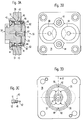
- Fig. 1 shows an embodiment of an axial piston machine, on which the Further development according to the invention is realized in an axial longitudinal section.
- the Axial piston machine 1 is designed in the exemplary embodiment in a sliding axis construction and comprises a drive shaft 2, which in a housing 3 by means of roller bearings 4 and 5th is rotatably mounted.
- a cylindrical drum 6 is in an angled housing part 3a a cylinder drum axis 7 rotatably arranged.
- the cylinder drum axis 7 is angled relative to the axis 8 of the drive shaft 2 by a predetermined angle.
- On the drive shaft 2 is at the end facing the cylinder drum 6 Formed drive flange 9.
- cylinder bores in the cylinder drum 6 10 there are several cylinder bores in the cylinder drum 6 10 is provided, in which associated pistons 11 are each slidably guided.
- the Pistons 11, which taper conically in the direction of a spherical head 12, are supported with their ball head 12 on the drive flange 9 and lead due to Angular misalignment between the axis 8 of the drive shaft 2 and the cylinder drum axis 7 with each revolution of the cylinder drum 6 and the drive shaft 2 in the associated Cylinder bores 10 a lifting movement.
- a bearing pin 13 is used to mount the cylinder drum 6, which Guide bore 14 of the cylinder drum 6 engages.
- the guide pin 13 has also a ball head 15, which is in a spherical bearing 16 of the Drive flange 9 supports.
- each piston 11 has a lubrication bore 18, which has a throttle point 19 communicates with a pressure pocket 32.
- the Guide pin 13 for lubrication and hydraulic relief of the spherical bearing 16 has a longitudinal bore 20 with connecting channels 21 and 22 in the drive shaft 2 is connected and is therefore connected to a lubrication circuit that can also serve the lubrication of the rolling bearings 4 and 5.
- a leak oil drain 23 is also provided in the housing 3 .
- the cylinder drum 6 is by means of a preferably designed as a plate spring compression spring 24 which in the guide bore 14th the cylinder drum 6 is inserted and against the ball head 15 supports the opposite end of the guide pin 13 against a control disk 25 biased.
- the control disc 25 is between the cylinder drum 6 and the Connection plate 26 arranged and fixed to the connection plate 26.
- kidney-shaped are shown in FIGS. 2D and 3D Control openings 27 and 28 provided to the cylinder bores 10 over Connection channels 29 cyclically with each revolution of the rotating cylinder drum 6 a low-pressure connection opening 60 provided in the connection plate 26 and one high pressure connection opening 61 also provided in the connection plate 26 connect.
- the connection plate is e.g. via mounting screws 30 and 31 on the housing 3 releasably attached.
- the control disk 25 to twist slightly with respect to the connecting plate 26, i.e. a minor one Subject to angular misalignment. Because this twist is basically in the direction of rotation takes place, it is when the direction of rotation of the axial piston machine 1 changes necessary to adapt this twist to the changed direction of rotation.
- the twist around the angle ⁇ is e.g. seen from Fig. 2D.
- connection plate 26 trained through holes 40 and 41 provided by the of the control disc 25 side facing away from the connecting plate 26 for inserting a fixing pin 43 are accessible.
- the through holes 40 and 41 are in the embodiment by means of two closure elements 42 and 44 closable, which in the through holes 40th and 41 e.g. are screwable to loosen or fall out of the fixing pin 43 prevent.
- the fixing pin 43 has a guide section 45 which can be seen better from FIG. 2C, which forms a fit with a guide section 46 of the through hole 40. If the fixing pin 43 is inserted into the other through hole 41 forms the Guide section 45 with the guide section 48 of the through hole 41 a appropriate fit.
- the control disc 25 is pivotally mounted in a retaining bolt 47 so that the Control disk 25 in a certain angle of rotation range around the cylinder drum axis 7 can be pivoted or rotated relative to the connecting plate 26.
- the Control disc also has two with the through holes 40 and 41 of the Connection plate 26 corresponding blind holes 49 and 50. How better from Fig. 2D can be seen that a top view of the one mounted on the connection plate 26 Control disc 25 shows, the blind holes 49 and 50 are double Twist angle 2 ⁇ offset from each other.
- the guide portion 46 of the through hole 40 is due to the in the Through hole 40 inserted fixing pin 43 concentric with the blind hole 49 aligned so that the guide portion 46 and the blind bore 49 in Fig. 2D collapse.
- the blind bore 50 is not concentric with that Guide portion 48 of the through hole 41 aligned, which is also in Fig. 2D is made clear.
- the fixing pin 43 has on its the control disc 25 facing end a conical section 53.
- the conical section 53 is like this shaped that the diameter at the tip of the fixing pin 43 is so small that the conical section 53 into the clear width not covered by the guide section 48 the blind bore 50 penetrates.
- the assembly effort for converting the axial piston machine 1 at one is due to the development according to the invention therefore reduced to a minimum.
- Fig. 2B shows the connection plate corresponding to Fig. 2A in a plan view accordingly the viewing direction marked with arrow 54.
- the through holes 40 and 41st close.
- the low pressure connection opening 60 and the high-pressure connection opening 61 can be seen. It can be seen that the Through holes 40 and 41 for the fixing pin 43 outside the connection openings 60 and 61 are arranged so that sealing problems are avoided.
- FIG. 2D shows the control disk 25 mounted on the connecting plate 26 accordingly the viewing direction indicated by arrow 55 in FIG. 2A.
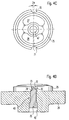
- 3A to 3D show a further development according to the invention with reference to the embodiment already described with reference to FIGS. 1 and 2A to 2D.
- Already elements described are identified by the same reference numerals, so that a description in this regard is unnecessary.
- 3A to 3D is in both Through holes 40 and 41 each inserted or inserted a fixing pin 43.
- the fixing pins 43 that can be seen in detail from FIG. 3C, however, have a slight modification compared to the fixing pin 43 described with reference to FIG. 2C.
- the guide section 45 is shortened in its axial length and, instead of a conical section 53, a tapered section 62 is provided, so that a stepped design of the fixing pin 43 results.
- the diameter of the tapered section 62 is half the size of the diameter of the guide section 45.
- FIG. 3B shows a top view of the connection plate 26 in a manner corresponding to FIG. 2B corresponding to the viewing direction indicated by arrow 54 in FIG. 3A.
- Fig. 3D shows, in a manner corresponding to FIG. 2D, a plan view of the connection plate 26 mounted control disc 25 according to the arrow 55 in Fig. 3A marked viewing direction.
- 3D shows the position of the tapered sections 62 of the two locating pins 43 with respect to the blind bores 49 and 50. Doing so clearly that the tapered portions 62 of the fixing pins 43 each in a half-surface the cross-sectional area of the blind bores 49 and 50 are arranged and on the The lateral surface of the blind bores 50 and 49 each lie flush on one side. To this A way of fixing the control disk 25 is shown in FIG. 3D Neutral position achieved.
- connection plate 26 does not have to be dismantled during the conversion work.
- the control disk 25 is slightly rotated in FIG. 3C Position shown again, that of the rotated position shown in Fig. 4D Fixing pin 43 corresponds.
- the fixing pin 43 can therefore in one certain range, the angular position of the control disk 25 and thus the Twist angle ⁇ can be adjusted. This fine adjustment allows the Optimize twist angle ⁇ so that there is an optimized noise behavior and a minimized pressure pulsation results.
- Through hole 41 of the connecting plate 46 can be in a corresponding manner trained fixing pin 43 may be used, the fixing pins 43 each in opposite directions are twisted to twist the control disk 25 and at the same time to fix it.
- the invention is not limited to the illustrated embodiment. In particular is it is also possible to provide several bores or recesses in the control disk, in order to vary the twist angle ⁇ for each direction of rotation.
Landscapes
- Engineering & Computer Science (AREA)
- Mechanical Engineering (AREA)
- General Engineering & Computer Science (AREA)
- Reciprocating Pumps (AREA)
Applications Claiming Priority (2)
| Application Number | Priority Date | Filing Date | Title |
|---|---|---|---|
| DE19643389 | 1996-10-21 | ||
| DE19643389A DE19643389C1 (de) | 1996-10-21 | 1996-10-21 | Axialkolbenmaschine mit variabler Fixierung der Steuerscheibe |
Publications (3)
| Publication Number | Publication Date |
|---|---|
| EP0837241A2 true EP0837241A2 (fr) | 1998-04-22 |
| EP0837241A3 EP0837241A3 (fr) | 1998-07-22 |
| EP0837241B1 EP0837241B1 (fr) | 2001-02-28 |
Family
ID=7809333
Family Applications (1)
| Application Number | Title | Priority Date | Filing Date |
|---|---|---|---|
| EP97117281A Expired - Lifetime EP0837241B1 (fr) | 1996-10-21 | 1997-10-06 | Machine à piston axial comportant un disque de commande ajustable |
Country Status (2)
| Country | Link |
|---|---|
| EP (1) | EP0837241B1 (fr) |
| DE (2) | DE19643389C1 (fr) |
Cited By (2)
| Publication number | Priority date | Publication date | Assignee | Title |
|---|---|---|---|---|
| WO2005042975A1 (fr) * | 2003-10-23 | 2005-05-12 | Brueninghaus Hydromatik Gmkh | Plaque de raccordement d'une machine hydrostatique et son procede de production |
| CN102220972A (zh) * | 2010-04-16 | 2011-10-19 | 罗伯特·博世有限公司 | 流体机械的机壳 |
Families Citing this family (2)
| Publication number | Priority date | Publication date | Assignee | Title |
|---|---|---|---|---|
| DE10344152A1 (de) | 2003-09-22 | 2005-04-21 | Klaus Riedel | Kombinationsschraube |
| DE102004061863A1 (de) * | 2004-12-22 | 2006-07-06 | Brueninghaus Hydromatik Gmbh | Kolben für Axialkolbenmaschine in Schrägachsenbauweise und Verfahren zur Herstellung solcher Kolben |
Citations (3)
| Publication number | Priority date | Publication date | Assignee | Title |
|---|---|---|---|---|
| US2546583A (en) | 1945-02-10 | 1951-03-27 | Denison Eng Co | Hydraulic apparatus |
| US3190232A (en) | 1963-02-11 | 1965-06-22 | Budzich Tadeusz | Hydraulic apparatus |
| EP0320822A1 (fr) | 1987-12-18 | 1989-06-21 | BRUENINGHAUS HYDRAULIK GmbH | Pompe à pistons axiaux |
Family Cites Families (4)
| Publication number | Priority date | Publication date | Assignee | Title |
|---|---|---|---|---|
| DE2406871B1 (de) * | 1974-02-13 | 1975-07-10 | Hydromatik Gmbh | Steuerspiegel einer hydraulischen Maschine |
| US4034652A (en) * | 1975-03-06 | 1977-07-12 | Caterpillar Tractor Co. | Method and valve face configuration for reducing noise in a hydraulic pump |
| FR2476762A2 (fr) * | 1980-02-22 | 1981-08-28 | Leduc & Fils Rene | Pompe hydraulique a plateau biais pouvant tourner dans les deux sens |
| FR2582738B1 (fr) * | 1985-05-31 | 1989-06-30 | Leduc Rene Hydro Sa | Machine hydraulique a pistons axiaux a distributeur central et flottant pouvant fonctionner soit en moteur, soit en pompe |
-
1996
- 1996-10-21 DE DE19643389A patent/DE19643389C1/de not_active Expired - Fee Related
-
1997
- 1997-10-06 DE DE59703045T patent/DE59703045D1/de not_active Expired - Fee Related
- 1997-10-06 EP EP97117281A patent/EP0837241B1/fr not_active Expired - Lifetime
Patent Citations (3)
| Publication number | Priority date | Publication date | Assignee | Title |
|---|---|---|---|---|
| US2546583A (en) | 1945-02-10 | 1951-03-27 | Denison Eng Co | Hydraulic apparatus |
| US3190232A (en) | 1963-02-11 | 1965-06-22 | Budzich Tadeusz | Hydraulic apparatus |
| EP0320822A1 (fr) | 1987-12-18 | 1989-06-21 | BRUENINGHAUS HYDRAULIK GmbH | Pompe à pistons axiaux |
Cited By (4)
| Publication number | Priority date | Publication date | Assignee | Title |
|---|---|---|---|---|
| WO2005042975A1 (fr) * | 2003-10-23 | 2005-05-12 | Brueninghaus Hydromatik Gmkh | Plaque de raccordement d'une machine hydrostatique et son procede de production |
| EP1757811A1 (fr) * | 2003-10-23 | 2007-02-28 | Brueninghaus Hydromatik Gmbh | Disque d'attachement pour une machine à piston hydrostatique et méthode de fabrication de ce disque |
| CN102220972A (zh) * | 2010-04-16 | 2011-10-19 | 罗伯特·博世有限公司 | 流体机械的机壳 |
| CN102220972B (zh) * | 2010-04-16 | 2015-08-19 | 罗伯特·博世有限公司 | 流体机械的机壳 |
Also Published As
| Publication number | Publication date |
|---|---|
| EP0837241B1 (fr) | 2001-02-28 |
| DE19643389C1 (de) | 1998-01-02 |
| EP0837241A3 (fr) | 1998-07-22 |
| DE59703045D1 (de) | 2001-04-05 |
Similar Documents
| Publication | Publication Date | Title |
|---|---|---|
| DE10336741B4 (de) | Anordnung eines stufenlosen Getriebes (CVT) und Verfahren zum axialen Positionieren von Riemenscheibenelementen eines CVT | |
| EP2179175B1 (fr) | Machine à piston axial du type à plateau oscillant, présentant un dispositif de réglage | |
| DE3942189C1 (fr) | ||
| DE69021397T2 (de) | Scheibe mit exzentrischer Kammer. | |
| EP0122378A1 (fr) | Soupape pour systèmes hydrauliques | |
| DE3519783A1 (de) | Axialkolbenmaschine | |
| DE9203378U1 (de) | Ölpumpe, insbesondere für eine Kettensäge | |
| EP0837241B1 (fr) | Machine à piston axial comportant un disque de commande ajustable | |
| DE19755386C2 (de) | Hydrostatische Maschine mit einer drehbar gelagerten Zylindertrommel und einer einstellbaren Schwenkscheibe | |
| DE69822203T2 (de) | Hydraulischer rotierender axialkolbenmotor | |
| DE69609582T2 (de) | Hydrostatische Pumpe und Mechanismus für die Synchronisierung der Lager | |
| DE2340664A1 (de) | Einstellbare axialkolbenmaschine mit bestimmter verdraengung | |
| EP0525507B1 (fr) | Dispositif de réglage d'un actionneur pour régler la cylindrée d'une machine hydrostatique | |
| DE19641865C2 (de) | Axialkolbenmaschine mit Haltevorrichtung für die Zylindertrommel | |
| EP0189786B1 (fr) | Machine à pistons axiaux | |
| DE10037481C1 (de) | Hydrostatische Verstellpumpe mit einem montage-verbesserten kompakten Gehäuse | |
| DE3733083A1 (de) | Verstellbare axialkolbenmaschine in schraegscheibenbauweise | |
| DE19544359C2 (de) | Radialkolbenmaschine | |
| EP4474644B1 (fr) | Pompe péristaltique | |
| DE218229C (fr) | ||
| DE4143020A1 (de) | Spindeltrieb | |
| DE2353779B1 (de) | Hydrostatische Kolbenmaschine | |
| WO2017020059A1 (fr) | Dispositif pour convertir une pression | |
| DE2825503A1 (de) | Einrichtung zum einspannen eines flanschlosen ventilgehaeuses | |
| AT398810B (de) | Schlauchpumpe |
Legal Events
| Date | Code | Title | Description |
|---|---|---|---|
| PUAI | Public reference made under article 153(3) epc to a published international application that has entered the european phase |
Free format text: ORIGINAL CODE: 0009012 |
|
| AK | Designated contracting states |
Kind code of ref document: A2 Designated state(s): DE FR GB IT SE |
|
| AX | Request for extension of the european patent |
Free format text: AL;LT;LV;RO;SI |
|
| PUAL | Search report despatched |
Free format text: ORIGINAL CODE: 0009013 |
|
| AK | Designated contracting states |
Kind code of ref document: A3 Designated state(s): AT BE CH DE DK ES FI FR GB GR IE IT LI LU MC NL PT SE |
|
| AX | Request for extension of the european patent |
Free format text: AL;LT;LV;RO;SI |
|
| 17P | Request for examination filed |
Effective date: 19980813 |
|
| AKX | Designation fees paid |
Free format text: DE FR GB IT SE |
|
| RBV | Designated contracting states (corrected) |
Designated state(s): DE FR GB IT SE |
|
| GRAG | Despatch of communication of intention to grant |
Free format text: ORIGINAL CODE: EPIDOS AGRA |
|
| GRAG | Despatch of communication of intention to grant |
Free format text: ORIGINAL CODE: EPIDOS AGRA |
|
| GRAH | Despatch of communication of intention to grant a patent |
Free format text: ORIGINAL CODE: EPIDOS IGRA |
|
| 17Q | First examination report despatched |
Effective date: 20000802 |
|
| GRAH | Despatch of communication of intention to grant a patent |
Free format text: ORIGINAL CODE: EPIDOS IGRA |
|
| GRAA | (expected) grant |
Free format text: ORIGINAL CODE: 0009210 |
|
| AK | Designated contracting states |
Kind code of ref document: B1 Designated state(s): DE FR GB IT SE |
|
| ITF | It: translation for a ep patent filed | ||
| REF | Corresponds to: |
Ref document number: 59703045 Country of ref document: DE Date of ref document: 20010405 |
|
| GBT | Gb: translation of ep patent filed (gb section 77(6)(a)/1977) |
Effective date: 20010405 |
|
| ET | Fr: translation filed | ||
| REG | Reference to a national code |
Ref country code: GB Ref legal event code: IF02 |
|
| PLBE | No opposition filed within time limit |
Free format text: ORIGINAL CODE: 0009261 |
|
| STAA | Information on the status of an ep patent application or granted ep patent |
Free format text: STATUS: NO OPPOSITION FILED WITHIN TIME LIMIT |
|
| 26N | No opposition filed | ||
| PGFP | Annual fee paid to national office [announced via postgrant information from national office to epo] |
Ref country code: DE Payment date: 20071025 Year of fee payment: 11 |
|
| PGFP | Annual fee paid to national office [announced via postgrant information from national office to epo] |
Ref country code: IT Payment date: 20071026 Year of fee payment: 11 |
|
| PGFP | Annual fee paid to national office [announced via postgrant information from national office to epo] |
Ref country code: SE Payment date: 20071012 Year of fee payment: 11 |
|
| PGFP | Annual fee paid to national office [announced via postgrant information from national office to epo] |
Ref country code: GB Payment date: 20071023 Year of fee payment: 11 Ref country code: FR Payment date: 20071016 Year of fee payment: 11 |
|
| EUG | Se: european patent has lapsed | ||
| GBPC | Gb: european patent ceased through non-payment of renewal fee |
Effective date: 20081006 |
|
| REG | Reference to a national code |
Ref country code: FR Ref legal event code: ST Effective date: 20090630 |
|
| PG25 | Lapsed in a contracting state [announced via postgrant information from national office to epo] |
Ref country code: IT Free format text: LAPSE BECAUSE OF NON-PAYMENT OF DUE FEES Effective date: 20081006 Ref country code: DE Free format text: LAPSE BECAUSE OF NON-PAYMENT OF DUE FEES Effective date: 20090501 |
|
| PG25 | Lapsed in a contracting state [announced via postgrant information from national office to epo] |
Ref country code: FR Free format text: LAPSE BECAUSE OF NON-PAYMENT OF DUE FEES Effective date: 20081031 |
|
| PG25 | Lapsed in a contracting state [announced via postgrant information from national office to epo] |
Ref country code: GB Free format text: LAPSE BECAUSE OF NON-PAYMENT OF DUE FEES Effective date: 20081006 |
|
| PG25 | Lapsed in a contracting state [announced via postgrant information from national office to epo] |
Ref country code: SE Free format text: LAPSE BECAUSE OF NON-PAYMENT OF DUE FEES Effective date: 20081007 |