EP0320822A1 - Pompe à pistons axiaux - Google Patents
Pompe à pistons axiaux Download PDFInfo
- Publication number
- EP0320822A1 EP0320822A1 EP88120650A EP88120650A EP0320822A1 EP 0320822 A1 EP0320822 A1 EP 0320822A1 EP 88120650 A EP88120650 A EP 88120650A EP 88120650 A EP88120650 A EP 88120650A EP 0320822 A1 EP0320822 A1 EP 0320822A1
- Authority
- EP
- European Patent Office
- Prior art keywords
- axial piston
- piston pump
- pump according
- channel
- pistons
- Prior art date
- Legal status (The legal status is an assumption and is not a legal conclusion. Google has not performed a legal analysis and makes no representation as to the accuracy of the status listed.)
- Granted
Links
- 238000005461 lubrication Methods 0.000 claims description 4
- 230000001105 regulatory effect Effects 0.000 claims 3
- 235000001674 Agaricus brunnescens Nutrition 0.000 claims 1
- 210000003734 kidney Anatomy 0.000 description 12
- 230000006835 compression Effects 0.000 description 3
- 238000007906 compression Methods 0.000 description 3
- 230000007423 decrease Effects 0.000 description 2
- 238000004519 manufacturing process Methods 0.000 description 2
- 238000009423 ventilation Methods 0.000 description 2
- 238000013022 venting Methods 0.000 description 2
- 238000010276 construction Methods 0.000 description 1
- 238000006073 displacement reaction Methods 0.000 description 1
- 239000010687 lubricating oil Substances 0.000 description 1
- 239000000463 material Substances 0.000 description 1
- 239000003921 oil Substances 0.000 description 1
- 230000000149 penetrating effect Effects 0.000 description 1
- 230000002093 peripheral effect Effects 0.000 description 1
- 238000005086 pumping Methods 0.000 description 1
- 230000003014 reinforcing effect Effects 0.000 description 1
- 238000009420 retrofitting Methods 0.000 description 1
Images


Classifications
-
- F—MECHANICAL ENGINEERING; LIGHTING; HEATING; WEAPONS; BLASTING
- F04—POSITIVE - DISPLACEMENT MACHINES FOR LIQUIDS; PUMPS FOR LIQUIDS OR ELASTIC FLUIDS
- F04B—POSITIVE-DISPLACEMENT MACHINES FOR LIQUIDS; PUMPS
- F04B1/00—Multi-cylinder machines or pumps characterised by number or arrangement of cylinders
- F04B1/12—Multi-cylinder machines or pumps characterised by number or arrangement of cylinders having cylinder axes coaxial with, or parallel or inclined to, main shaft axis
- F04B1/20—Multi-cylinder machines or pumps characterised by number or arrangement of cylinders having cylinder axes coaxial with, or parallel or inclined to, main shaft axis having rotary cylinder block
- F04B1/2014—Details or component parts
- F04B1/2042—Valves
Definitions
- the invention relates to an axial piston pump according to the preamble of claim 1.
- the invention is based on the object of designing an axial piston pump of the type described at the outset, that it can be adapted to the other direction of conveyance with less effort.
- the axial piston pump can be adapted to the desired delivery direction by rotating the control part through 180 °. There is therefore no need for an additional connecting part, as is the case with the known configuration.
- the connecting part is rotated, there is a displacement of the suction and discharge openings with respect to the axial piston pump or the machine receiving it, but this problem can be solved in a simple manner by using flexible connecting lines or suitable connecting line sections.
- the retrofitting of the axial piston pump according to the invention is very simple because it only requires a solution and removal of the existing fastening screws for the connecting part.
- the connecting part can then be rotated in a simple manner by 180 °, an advantageously existing centering projection with a round cross section between the connecting part and the housing of the axial piston machine being able to serve as a rotary bearing.
- the configuration according to the invention is suitable for those axial piston pumps in which the delivery direction is changed by changing the direction of rotation of the drive shaft or, in the case of axial piston pumps, adjustable delivery rate by adjusting the adjusting device beyond the zero point.
- a simple and practical channel guide for loading the adjusting device of the axial piston pump is proposed, which is functional and advantageous in both mounting positions of the connecting part.
- the swash plate is pivoted out by the engine forces of the axial piston pump, so that no additional pivoting mechanism is required.
- the swash plate is simple and easy to assemble or disassemble.
- the features of claim 11 ensure simple and inexpensive manufacture, the bearing bodies being able to be produced from finished balls by reworking such as turning.
- Claims 12 and 13 relate to mechanical stops, in particular to prevent the swivel plate from overshooting when pouring at high positioning speeds.
- the bearing that is more heavily loaded is starting from the slideway of the swash plate, intermittent and from the height of the operating pressure is supplied with pressure oil by the pistons and is therefore advantageously lubricated.
- This configuration enables low-friction and low-wear operation with fast positioning times.
- the axial piston pump generally designated 1 in FIG. 1 has a two-part housing consisting of a cup-shaped housing part 2 and a connecting plate 3, in which a drive shaft 5 extending along the central axis 4 is mounted in roller bearings 6, 7, of which one the cup-shaped housing part 2 and the other of the connection plate 3 is assigned.
- a cylinder drum 9 is mounted on the drive shaft 5 on a multi-key section designated 8, which cylinder cylinder 9 has a plurality of cylinder bores 11, in which pistons 12 are accommodated, evenly distributed over a pitch circle.
- the pistons 12 have ball heads 13 which enclose in sliding shoes 14 which rest on the sliding surface 15 of a swash plate 16.
- a retraction plate 17 which, in the present exemplary embodiment, is mounted on a spherical head-shaped carrier piece 19 with a recess 18 in the form of a spherical segment.
- the carrier piece 19 is mounted on the drive shaft 5 so as to be longitudinally displaceable.
- the swash plate 16 is mounted about a swivel axis 22 in a swivel bearing which is formed by two supports, generally designated 23, lying one behind the other along the swivel axis 22, consisting of two mushroom-shaped bearing pieces 24 which, with their pins 25 round in cross section, in bores 26 in Bottom of the cup-shaped housing part 2 are inserted and surround in spherical recesses 27 on the back of the swash plate 16.
- the spherical convex surfaces of the bearing pieces 24 facing the pistons and the spherical concave surfaces of the recesses 27 thus form housing-side and swashplate-side bearing surfaces 28.
- pan-shaped bearing shells 29 are used in the recesses 27, each with a radially projecting collar 31 on the peripheral edge of the Recesses 27 abut and are thus secured against tilting movements.
- the pivot axis 22 of the swash plate 16 is located at a distance a from the line of action of the piston force 32 resulting from the forces of the active pistons 12, this distance a extending beyond the central axis 4.
- the resulting piston force 32 is generated by the pistons 12 located on the respective pressure side. Due to the distance a, the swash plate 16 is loaded with a torque according to FIG. 1 counterclockwise during operation of the axial piston pump 1.
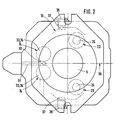
- swash plate 16 bears against its adjusting hydraulic adjusting pistons 33, which are arranged parallel to the drive shaft 5 in the base or flange part of the cup-shaped housing part 2 and are hydraulically displaceable in cylinder bores 34 axially parallel to the drive shaft 5, ie in the direction of the double arrow 35 .
- the adjusting pistons 33 are arranged opposite the effective resulting piston force 32, that is to say they are located on the other side of the axial piston pump 1 with respect to the pivot axis 22, being at an equal distance from the central axis 4, fairly close to one another and symmetrical to one perpendicular to the pivot axis 22 extending transverse axis 36 are arranged, cf. Fig. 2. In the position shown in FIG.
- the swash plate 16 is in its maximum piston stroke position.
- the actuating piston 33 By extending the actuating piston 33, the swash plate 16 can be adjusted about the pivot axis 22 in either pivot positions or delivery rate settings.
- stops 37 are arranged approximately opposite each other on both sides of the axial transverse plane 36, the actuating pistons 33, which are formed by bolts or screws 38 with stop pins inserted laterally into the housing part 2 from the outside.
- the axial piston machine 1 is set to a minimum piston stroke and a minimum delivery rate.
- the swivel bearings 23 are each provided with a lubrication channel 39 which extends from the recess 27 and crosses the bearing shell 29 and the swash plate 16 connected to the oil-carrying system of the axial piston machine 1 and thus oil-lubricated.
- the lubrication channel 39 opens into the sliding surface 15 of the swash plate 16 in the vicinity of the pitch circle on which the pistons 12 are arranged, specifically in an area which the sliding shoes 14 cover with a recess 41 in their sliding surface 42.
- the recess 41 is connected to the working spaces 45 of the piston cylinders by means of axial channels 43, 44 in the sliding shoes 14 and the pistons 12, which are known per se. In this way, during operation of the axial piston pump 1, the bearing point of the pivot bearing 23, which is subjected to higher loads, is intermittently supplied with lubricating oil under working pressure when the sliding shoes 14 are swept over.
- the cylinder drum 9 lies with its end facing away from the swash plate 16 against a control plate 46 which is arranged between the cylinder drum 9 and the connection plate 3 and is held on the connection plate 3 in a rotationally fixed manner about the central axis 4.
- the control plate 46 shown in detail in FIG. 3 has two essentially kidney-shaped control openings 47, 48 penetrating it, to which kidney-shaped suction and pressure channels 51, 52 also adjoin in the connection plate 3, of which the suction channel 51 is opposite the pressure channel 52 end cross enlarged in cross section cut, namely a large suction opening 53, here a connection for a suction line, not shown, has.
- the control kidney 48 is interrupted on the pressure side by reinforcing webs 50.
- Known pressure compensation notches 55, 56 are arranged at the ends of the control kidneys 47, 48, which are opposite to the respective direction of rotation, which is exemplified by the arrow 54 in FIG to be reduced if the control channels 57 which are present in the cylinder drum 9 and extend from the working spaces 45 come into contact with the control kidneys 47, 48 containing high or low pressure.
- the control plate 46 has pressure compensation notches 55 on both sides, namely at one and the same end of at least the high-pressure control kidney 48. That is, on the rear of the control plate 46 according to FIG. 3 there are also pressure compensation notches 55, 56 behind the visible pressure compensation notches 55 , 56 available.
- the pressure compensation notches 55, 56 extend from the relevant end of the control kidneys 47, 48 and converge in a wedge shape, as shown in the partial section according to FIG. 4.
- the pressure compensation notch (s) 55 are optionally on both sides of the control plate 46, preferably in the direction of rotation 54 opposite end of the low-pressure control kidney 47 arranged.
- the control plate 46 is secured against rotation by means of a pin connection with a pin, preferably starting from the connecting plate 3 (FIG. 5), which enters a blind hole or through-hole in the control plate 46 borders.
- the arrangement is such that the control plate 46 can optionally be attached to one or the other end face of the connection plate 3, namely that it can be folded essentially about a transverse axis 58 parallel to the transverse axis 36 according to FIG. 2, so that the control kidneys 47 , 48 always correspond to the likewise kidney-shaped suction or pressure channels 51, 52 in the connection plate 3.
- the arrangement of the pin 60 and a pin hole 61 which receives the pin 60 and passes through here is preferably such that the two optional mounting positions of the control plate 46 differ with respect to the position specified by the connecting plate 3, namely that one mounting position is opposite the one another mounting position offset in the circumferential direction, which is illustrated by the angle b shown in FIG. 4, which represents an offset of the pin hole 61 to the transverse axis 58. That is, the control kidneys 47, 48 are not symmetrical with respect to the arrangement predetermined by the control channels 57, specifically for functional reasons in order to achieve a certain advance, which is known per se.
- the angle b 1 in Fig. 3 shows the angular offset in the folded mounting position of the control plate 46th
- control plate 46 is configured in parallel.
- the cylinder drum 9 is rotated by the drive shaft 5.
- the cylinder bores 11 are mutually connected to the control kidneys 47, 48 via the control channels 57, as a result of which the pumping action results in a known manner due to the movement of the pistons 12.
- the direction of flow of the hydraulic medium is in Fig. 1 by arrows 62 and 63 clarifies.
- the seal between the cylinder drum 9 and the control plate 46 is ensured by a compression spring 64 which is clamped between an inner ring 65 of the cylinder drum 9 and a pressure ring.
- At least one axial pressure element in the present exemplary embodiment extends in the form of three pressure pins 66 distributed over the circumference, which are axially displaceable in a guide of the cylinder drum 9, between the pressure ring and the carrier piece 19.
- the compression spring 64 By means of the compression spring 64, the cylinder drum 9 is thus acted upon elastically against the control plate 46 and the carrier piece 19 against the retraction plate 17 and consequently also the swash plate 16 against the support 23.
- a comparable purpose could also advantageously be achieved by, for example, compression springs arranged in the cylinder bores 11, which act on the pistons 12 in the direction of the swash plate 16.
- connection plate 3 is designed such that it can be mounted rotated by 180 ° about the central axis 4. This applies in particular to the four fastening screws 67 evenly distributed on a pitch circle in the present exemplary embodiment and the configurations relating to the control arrangement, such as the kidney-shaped suction or pressure channel sections 51, 52, the pin connection between the connecting plate 3 and the control plate 46 and the general with 68 designated centering with a round cross-section 69 on the connecting plate 3, which roughly encloses in the cross-section also round cavity 71 of the housing.
- the connection plate 3 can thus be rotated and loosened after loosening and removing the fastening screws 67 by 180 °.
- the axial piston machine 1 can be adapted in a simple manner to a reversal of the conveying direction arrange the suction opening 53, which is larger in cross section, into the position predetermined by the reversal of the direction of flow, namely either on one side or the other of the axial piston machine 1, so that trouble-free suction or a trouble-free filling of the suction piston cylinders is achieved.
- connection plate 3 is made of drawn profile material, preferably a square cross-section. This enables cost-effective production.
- the fastening screws 67 are arranged in an opposite position in the corner region of the connection plate 3.
- the assembly or disassembly of the swash plate 16 is very simple, because after removal of the connection plate 3 both individually and on the drive shaft 5 as a pre-assembled unit inserted from the open side of the housing into the housing part 2 and can be removed in the opposite direction .
- a valve, generally designated 72, is provided for adjusting the delivery rate of the axial piston pump 1, with which it is possible to regulate the delivery rate setting in dependence on the existing working pressure in such a way that the delivery rate decreases with increasing working pressure and the delivery rate increases with falling working pressure ( Pressure control) or the flow rate is only limited depending on the pressure.
- valve 72 is arranged in a line connecting the pressure channel 52 with the working spaces 73 of the adjusting cylinder, generally designated 74, in order to regulate or control the action on the adjusting piston 33.
- This consists of several sections and Connection channel designated 75 is connected to the pressure channel 52 in the area of the connection plate 3.
- two connecting channel branches 76, 77 drilled and closed from outside are provided in the connecting plate 3 (FIG. 5).
- the one connecting channel branch 76 corresponds in one assembly position and the other connecting channel branch 77 in the other mounting position of the connecting plate 3 rotated by 180 ° at the interface designated 78 (FIG. 1) of the connecting channel 75.
- This interface 78 is located in the parting line between the housing part 2 and the connection plate 3, and it is sealed off from the parting line in a manner not shown.
- the connecting channel 75 initially runs axially in the housing part 2 in the region of the valve 72, which is attached laterally and preferably symmetrically to an attachment surface 79 and is fastened in a manner not shown, the valve housing of which is generally designated 81.
- the valve 72 has a valve slide 82 with a collar which has control edges on both sides and which forms a variable valve opening with a connecting channel section 87 extending from the bore 86 receiving the slide 82 to the working spaces 73.
- the slide 82 is urged at its upper end in FIG. 1 by a spring 89 into a position closing the valve opening.
- the slide 82 is pressed up against the spring 89, as a result of which the passage on the connecting channel section 87 is opened and the adjusting pistons 33 are hydraulically extended via connecting channel branches 91, 92 (FIG. 2) in order to reduce or limit the delivery rate.
- the connecting channel sections 91, 92 are each connected via a circumferential groove 93 and a radial and axial connecting channel section 94.95 (FIG. 1) in the adjusting piston 33 to the working spaces 73 of the adjusting cylinders 74.
- venting channel sections 98, 99, 100 which are connected to the housing cavity 71 of the pump housing.
- the ventilation duct section 98 is formed by the bore section 86 lying behind the collar, i.e. this ventilation duct section 98 starts from the valve opening and is closed when the adjusting piston 33 is acted upon by the collar.
- the biasing force of the spring 89 is adjustable by means of an adjusting screw 101, against which the spring 89 is supported via a spring actuator 102.
- the adjusting screw 101 can be secured by a nut 103.
- valve 72 It is possible within the scope of the invention to design the valve 72 and to make the arrangement such that it can adjust the swash plate 16 between only two positions, namely between the maximum and minimum settings.
- control disk 46 the control kidneys 47, 48 of which are arranged symmetrically with respect to the transverse plane 36, which is also designated in FIG. 5.
- suction opening 53 which is larger in cross section
- discharge opening 104 which is smaller in cross section
- suction and pressure channels 51, 52 and the control kidneys 47, 48 in FIG. 1 are shown rotated by 90 ° in order to improve understanding, which is illustrated by a broken line.
- the aforementioned design features lie on both sides of the transverse plane 36 (see FIG. 5), which also represents the sectional plane according to FIG. 1, and in which the transverse axis 58 also lies.
- the adjustment of the axial piston machine 1 with respect to the implementation of the control disk 46 can also be carried out in that the control disk or control plate 46 is rotated about the central axis 4 by essentially 180 °, in contrast to the folding in the exemplary embodiment described above.
- Such an embodiment is thus also functional in order to adapt the axial piston pump 1 to the reversal of the conveying direction.
- the reversal of the conveying direction is achieved by changing the direction of rotation of the drive shaft 5.
- a reversal of the conveying direction can also be achieved in that the existing adjusting device of the axial piston pump, in contrast to the exemplary embodiment according to FIG. 1, can be adjusted beyond the zero point.
Landscapes
- Engineering & Computer Science (AREA)
- Mechanical Engineering (AREA)
- General Engineering & Computer Science (AREA)
- Reciprocating Pumps (AREA)
Applications Claiming Priority (2)
| Application Number | Priority Date | Filing Date | Title |
|---|---|---|---|
| DE3743125 | 1987-12-18 | ||
| DE19873743125 DE3743125A1 (de) | 1987-12-18 | 1987-12-18 | Axialkolbenpumpe |
Publications (3)
| Publication Number | Publication Date |
|---|---|
| EP0320822A1 true EP0320822A1 (fr) | 1989-06-21 |
| EP0320822B1 EP0320822B1 (fr) | 1991-03-06 |
| EP0320822B2 EP0320822B2 (fr) | 1997-01-29 |
Family
ID=6343006
Family Applications (1)
| Application Number | Title | Priority Date | Filing Date |
|---|---|---|---|
| EP88120650A Expired - Lifetime EP0320822B2 (fr) | 1987-12-18 | 1988-12-09 | Pompe à pistons axiaux |
Country Status (4)
| Country | Link |
|---|---|
| US (1) | US4934253A (fr) |
| EP (1) | EP0320822B2 (fr) |
| JP (1) | JP2554927B2 (fr) |
| DE (2) | DE3743125A1 (fr) |
Cited By (4)
| Publication number | Priority date | Publication date | Assignee | Title |
|---|---|---|---|---|
| WO1996001947A1 (fr) * | 1994-07-08 | 1996-01-25 | Danfoss A/S | Piston a patin coulissant et son procede de production |
| DE19643389C1 (de) * | 1996-10-21 | 1998-01-02 | Brueninghaus Hydromatik Gmbh | Axialkolbenmaschine mit variabler Fixierung der Steuerscheibe |
| WO2008071374A1 (fr) * | 2006-12-11 | 2008-06-19 | Robert Bosch Gmbh | Machine à pistons axiaux et plaque de commande pour une machine à pistons axiaux |
| WO2014187545A1 (fr) * | 2013-05-22 | 2014-11-27 | Hydac Drive Center Gmbh | Pompe à pistons axiaux |
Families Citing this family (66)
| Publication number | Priority date | Publication date | Assignee | Title |
|---|---|---|---|---|
| JP2500892Y2 (ja) * | 1989-08-31 | 1996-06-12 | 帝人製機株式会社 | 可変型油圧アクチュエ―タ |
| JP2559632B2 (ja) * | 1989-11-22 | 1996-12-04 | 株式会社小松製作所 | 斜板式ピストンポンプ・モータの斜板角度変更装置 |
| DE3942189C1 (fr) * | 1989-12-20 | 1991-09-05 | Hydromatik Gmbh, 7915 Elchingen, De | |
| DE4229007C2 (de) * | 1992-08-31 | 2002-06-13 | Linde Ag | Axialkolbenmaschine in Schrägscheibenbauweise |
| DE4301121C2 (de) * | 1993-01-18 | 1995-03-30 | Danfoss As | Hydraulische Axialkolbenmaschine mit einer Schrägscheibe |
| US5423560A (en) * | 1994-03-17 | 1995-06-13 | Warrick; John J. | Variable speed hydraulic drive, for single or multi-wheel drive bicycles and the like |
| JP3179296B2 (ja) * | 1994-08-11 | 2001-06-25 | 株式会社ゼクセルヴァレオクライメートコントロール | 可変容量型揺動板式圧縮機のヒンジボール |
| DE19503617C2 (de) * | 1995-02-03 | 1999-06-02 | Sauer Sundstrand Gmbh & Co | Druckmittelaggregat mit variablem Hubvolumen |
| DE19521574A1 (de) * | 1995-06-14 | 1996-12-19 | Rexroth Mannesmann Gmbh | Hydrostatische Maschine |
| KR100298021B1 (ko) * | 1996-10-08 | 2002-04-06 | 세구치 류이치 | 사판식액압회전기및이회전기용케이싱의제조방법 |
| SE514196C2 (sv) * | 1997-12-08 | 2001-01-22 | Parker Hannifin Ab | Hydraulisk roterande axialkolvmaskin |
| SE521484C2 (sv) | 1998-02-13 | 2003-11-04 | Parker Hannifin Ab | Hydraulisk roterande axialkolvmaskin |
| SE514384C2 (sv) | 1998-04-17 | 2001-02-19 | Parker Hannifin Ab | Hydraulisk roterande axialkolvmaskin |
| US6027250A (en) * | 1998-08-21 | 2000-02-22 | The Torrington Company | Roller bearing segment for swashplates and other limited-oscillation applications |
| US6358018B1 (en) | 1999-02-12 | 2002-03-19 | Parker Hannifin Ab | Hydraulic rotating axial piston engine |
| US6889595B1 (en) | 1999-07-16 | 2005-05-10 | Hydro-Gear Limited Partnership | Pump |
| US6332393B1 (en) | 1999-07-16 | 2001-12-25 | Hydro-Gear Limited Partnership | Pump |
| US7178336B1 (en) | 1999-07-16 | 2007-02-20 | Hydro-Gear Limited Partnership | Pump |
| US6694729B1 (en) | 1999-07-16 | 2004-02-24 | Hydro-Gear Limited Partnership | Pump |
| US7082762B1 (en) | 1999-07-16 | 2006-08-01 | Hydro-Gear Limited Partnership | Pump |
| US6354809B1 (en) | 2000-01-27 | 2002-03-12 | Ford Global Technologies, Inc. | Variable swash plate compressor |
| US6210124B1 (en) | 2000-01-27 | 2001-04-03 | Ford Global Technologies, Inc. | Variable swash plate compressor |
| DE10044784B4 (de) * | 2000-09-11 | 2006-03-23 | Sauer-Danfoss (Neumünster) GmbH & Co OHG | Schrägachsenverstelleinheit |
| US6793463B1 (en) | 2000-10-30 | 2004-09-21 | Hydro-Gear Limited Partnership | Tandem pump and interface for same |
| US6494686B1 (en) | 2000-10-30 | 2002-12-17 | Hydro-Gear Limited Partnership | Tandem pump and interface for same |
| DE10154723A1 (de) | 2000-11-10 | 2002-10-31 | Parker Hannifin Corp | Axialkolbenpumpe mit interner Vorverdichtung |
| US6675696B1 (en) * | 2001-12-14 | 2004-01-13 | Hydro-Gear Limited Partnership | Pump and center section for hydrostatic transmission |
| US6672843B1 (en) | 2002-04-08 | 2004-01-06 | Hydro-Gear Limited Partnership | Dual pump apparatus comprising dual drive shafts and auxiliary pump |
| US20040175277A1 (en) * | 2002-06-28 | 2004-09-09 | Cox C. Paul | Hydrostatic pump assembly having symmetrical endcap |
| TW565652B (en) * | 2002-12-13 | 2003-12-11 | Ind Tech Res Inst | Stirling engine with variable stroke |
| EP1435457A1 (fr) * | 2003-01-03 | 2004-07-07 | Lavorwash S.p.A. | Pompe axiale avec dispositif automatique de réglage du débit |
| US6953327B1 (en) | 2003-03-11 | 2005-10-11 | Hydro-Gear Limited Partnership | Dual pump |
| WO2004113724A2 (fr) * | 2003-06-18 | 2004-12-29 | Thomas Industries Inc. | Pompe a nutation hybride |
| US7007468B1 (en) | 2003-06-27 | 2006-03-07 | Hydro-Gear Limited Partnership | Charge pump for a hydrostatic transmission |
| US7278263B1 (en) | 2003-06-27 | 2007-10-09 | Hydro-Gear Limited Partnership | Charge pump for a hydraulic pump |
| JP4425590B2 (ja) * | 2003-09-09 | 2010-03-03 | 株式会社 神崎高級工機製作所 | ポンプユニット |
| DE102004007933B3 (de) * | 2004-02-18 | 2005-06-16 | Sauer-Danfoss (Neumünster) GmbH & Co OHG | Axialkolbenmaschine mit einer Vorsteuerungseinrichtung zur Dämpfung von Strömungspulsationen und Herstellungsverfahren |
| US7216876B2 (en) * | 2004-06-21 | 2007-05-15 | Cole Jeffrey E | Occupant-propelled fluid powered rotary device, truck, wheeled platform, or vehicle |
| US7232139B2 (en) * | 2004-06-21 | 2007-06-19 | Cole Jeffrey E | Truck assembly for a skateboard, wheeled platform, or vehicle |
| WO2006002205A2 (fr) | 2004-06-21 | 2006-01-05 | Cole Jeffrey E | Ensemble de roulement pour planche a roulettes, plate-forme a roues, ou vehicule |
| US7040638B2 (en) * | 2004-06-21 | 2006-05-09 | Jeffrey Eaton Cole | Occupant-propelled fluid powered rotary device, truck, wheeled platform, or vehicle |
| US7789846B2 (en) * | 2005-01-25 | 2010-09-07 | Thermopeutix, Inc. | System and methods for selective thermal treatment |
| US7635136B2 (en) * | 2005-06-21 | 2009-12-22 | Jeffrey E. Cole | Truck assembly for a skateboard, wheeled platform, or vehicle |
| EP1780410B1 (fr) * | 2005-10-26 | 2013-04-03 | Poclain Hydraulics | Machine hydraulique à déplacement variable avec plateau en biais |
| US7451687B2 (en) * | 2005-12-07 | 2008-11-18 | Thomas Industries, Inc. | Hybrid nutating pump |
| US7257948B1 (en) | 2005-12-21 | 2007-08-21 | Hydro-Gear Limited Partnership | Dual pump apparatus |
| US7726126B1 (en) | 2005-12-21 | 2010-06-01 | Hydro-Gear Limited Partnership | Dual pump apparatus with power take off |
| WO2008116136A1 (fr) * | 2007-03-21 | 2008-09-25 | Gardner Denver Thomas, Inc. | Pompe de nutation hybride avec particularité antirotation |
| US7806040B2 (en) * | 2007-09-12 | 2010-10-05 | Sauer-Danfoss Inc. | Ball supported swashplate for axial piston hydraulic machine |
| USD616622S1 (en) * | 2009-01-27 | 2010-05-25 | Waste-Not-Basket, Inc. | Wastebasket |
| JP4934749B1 (ja) * | 2011-02-23 | 2012-05-16 | 株式会社小松製作所 | 可変容量型油圧ポンプ・モータ |
| US9103339B2 (en) | 2011-02-28 | 2015-08-11 | James H. Gammon | Piston pump |
| DE102013211450A1 (de) * | 2013-06-19 | 2014-12-24 | Robert Bosch Gmbh | Axialkolbenmaschine mit einer Schmierbohrung für den Stellkolben |
| CN103486016A (zh) * | 2013-09-16 | 2014-01-01 | 同济大学 | 一种低噪声抗气蚀柱塞泵用配流盘 |
| DE112014005946A5 (de) * | 2013-12-18 | 2016-10-06 | Schaeffler Technologies AG & Co. KG | Verstellpumpe |
| DE102015212731A1 (de) | 2015-07-08 | 2017-01-12 | Robert Bosch Gmbh | Gehäuse für eine hydrostatische Axialkolbenmaschine und hydrostatische Axialkolbenmaschine mit einem Gehäuse |
| CH712152A1 (de) * | 2016-02-25 | 2017-08-31 | Liebherr Machines Bulle Sa | Axialkolbenmaschine, insbesondere Axialkolbenpumpe. |
| DE102017206901A1 (de) | 2017-04-25 | 2018-10-25 | Robert Bosch Gmbh | Hydrostatische Axialkolbenmaschine |
| DE102018205884A1 (de) * | 2018-04-18 | 2019-10-24 | Robert Bosch Gmbh | Axialkolbenmaschine mit Druckentlastung in den Durchtriebsraum |
| US11236736B2 (en) * | 2019-09-27 | 2022-02-01 | Honeywell International Inc. | Axial piston pump with port plate having balance feed aperture relief feature |
| USD1058606S1 (en) | 2023-08-07 | 2025-01-21 | Caterpillar Inc. | Piston pump |
| USD1058604S1 (en) | 2023-08-07 | 2025-01-21 | Caterpillar Inc. | Piston pump |
| USD1058607S1 (en) | 2023-08-07 | 2025-01-21 | Caterpillar Inc. | Piston pump |
| USD1058605S1 (en) | 2023-08-07 | 2025-01-21 | Caterpillar Inc. | Piston pump |
| USD1058608S1 (en) | 2023-08-07 | 2025-01-21 | Caterpillar Inc. | Piston pump |
| USD1060434S1 (en) | 2023-08-07 | 2025-02-04 | Caterpillar Inc. | Piston pump |
Citations (5)
| Publication number | Priority date | Publication date | Assignee | Title |
|---|---|---|---|---|
| FR15964E (fr) * | 1910-12-08 | 1912-10-26 | Louis Brun | Moteur rotatif reversible |
| DE1098780B (de) * | 1955-12-02 | 1961-02-02 | Daimler Benz Ag | Steuerung der Zu- und Ableitung von Betriebsfluessigkeit eines hydrostatischen Axialkolbengetriebes |
| DE1291632B (de) * | 1963-06-19 | 1969-03-27 | Lucas Industries Ltd | Einrichtung zum Aufrechterhalten der Spaltbreite zwischen der umlaufenden Zylindertrommel und dem Steuerspiegel einer Druckfluessigkeits-Axialkolbenmaschine |
| FR2082604A5 (fr) * | 1970-03-20 | 1971-12-10 | Boyer Jean | |
| US4550645A (en) * | 1984-04-27 | 1985-11-05 | Sundstrand Corporation | Thin valve plate for a hydraulic unit |
Family Cites Families (7)
| Publication number | Priority date | Publication date | Assignee | Title |
|---|---|---|---|---|
| US3585901A (en) * | 1969-02-19 | 1971-06-22 | Sundstrand Corp | Hydraulic pump |
| DE1939297A1 (de) * | 1969-08-01 | 1971-02-11 | Linde Ag | Axialkolbenmaschine |
| DE2208890A1 (de) * | 1972-02-25 | 1973-09-06 | Bosch Gmbh Robert | Axialkolbenpumpe |
| US4034652A (en) * | 1975-03-06 | 1977-07-12 | Caterpillar Tractor Co. | Method and valve face configuration for reducing noise in a hydraulic pump |
| FR2476762A2 (fr) * | 1980-02-22 | 1981-08-28 | Leduc & Fils Rene | Pompe hydraulique a plateau biais pouvant tourner dans les deux sens |
| DE3233579C2 (de) * | 1982-09-10 | 1984-09-13 | Hermann Hemscheidt Maschinenfabrik Gmbh & Co, 5600 Wuppertal | Axialkolbenmaschine |
| FR2582738B1 (fr) * | 1985-05-31 | 1989-06-30 | Leduc Rene Hydro Sa | Machine hydraulique a pistons axiaux a distributeur central et flottant pouvant fonctionner soit en moteur, soit en pompe |
-
1987
- 1987-12-18 DE DE19873743125 patent/DE3743125A1/de not_active Withdrawn
-
1988
- 1988-12-09 EP EP88120650A patent/EP0320822B2/fr not_active Expired - Lifetime
- 1988-12-09 DE DE8888120650T patent/DE3861956D1/de not_active Expired - Lifetime
- 1988-12-13 US US07/283,622 patent/US4934253A/en not_active Expired - Lifetime
- 1988-12-19 JP JP63320297A patent/JP2554927B2/ja not_active Expired - Fee Related
Patent Citations (5)
| Publication number | Priority date | Publication date | Assignee | Title |
|---|---|---|---|---|
| FR15964E (fr) * | 1910-12-08 | 1912-10-26 | Louis Brun | Moteur rotatif reversible |
| DE1098780B (de) * | 1955-12-02 | 1961-02-02 | Daimler Benz Ag | Steuerung der Zu- und Ableitung von Betriebsfluessigkeit eines hydrostatischen Axialkolbengetriebes |
| DE1291632B (de) * | 1963-06-19 | 1969-03-27 | Lucas Industries Ltd | Einrichtung zum Aufrechterhalten der Spaltbreite zwischen der umlaufenden Zylindertrommel und dem Steuerspiegel einer Druckfluessigkeits-Axialkolbenmaschine |
| FR2082604A5 (fr) * | 1970-03-20 | 1971-12-10 | Boyer Jean | |
| US4550645A (en) * | 1984-04-27 | 1985-11-05 | Sundstrand Corporation | Thin valve plate for a hydraulic unit |
Cited By (8)
| Publication number | Priority date | Publication date | Assignee | Title |
|---|---|---|---|---|
| WO1996001947A1 (fr) * | 1994-07-08 | 1996-01-25 | Danfoss A/S | Piston a patin coulissant et son procede de production |
| DE19643389C1 (de) * | 1996-10-21 | 1998-01-02 | Brueninghaus Hydromatik Gmbh | Axialkolbenmaschine mit variabler Fixierung der Steuerscheibe |
| EP0837241A2 (fr) | 1996-10-21 | 1998-04-22 | Brueninghaus Hydromatik Gmbh | Machine à piston axiaux comportant un disque de commande adjustable |
| WO2008071374A1 (fr) * | 2006-12-11 | 2008-06-19 | Robert Bosch Gmbh | Machine à pistons axiaux et plaque de commande pour une machine à pistons axiaux |
| WO2014187545A1 (fr) * | 2013-05-22 | 2014-11-27 | Hydac Drive Center Gmbh | Pompe à pistons axiaux |
| WO2014187546A1 (fr) * | 2013-05-22 | 2014-11-27 | Hydac Drive Center Gmbh | Pompe à pistons axiaux |
| AU2018204390B2 (en) * | 2013-05-22 | 2020-01-02 | Hydac Drive Center Gmbh | Axial piston pump |
| US10527029B2 (en) | 2013-05-22 | 2020-01-07 | Hydac Drive Center Gmbh | Axial piston pump |
Also Published As
| Publication number | Publication date |
|---|---|
| JP2554927B2 (ja) | 1996-11-20 |
| JPH01200068A (ja) | 1989-08-11 |
| EP0320822B2 (fr) | 1997-01-29 |
| DE3743125A1 (de) | 1989-07-06 |
| EP0320822B1 (fr) | 1991-03-06 |
| DE3861956D1 (de) | 1991-04-11 |
| US4934253A (en) | 1990-06-19 |
Similar Documents
| Publication | Publication Date | Title |
|---|---|---|
| EP0320822B1 (fr) | Pompe à pistons axiaux | |
| DE3590198C2 (de) | Ventilplatte für eine hydrostatische Axialkolbeneinheit | |
| DE69604551T2 (de) | Hydrostatisches, stufenloses getriebe | |
| DE10161131A1 (de) | Flügelpumpe veränderlicher Verdrängung | |
| DE2533498A1 (de) | Steuerungssystem fuer eine axialkolbenmaschine zur stroemungsenergieuebertragung | |
| DE3500298C2 (fr) | ||
| DE10037482C1 (de) | Hydrostatische Verstellpumpe mit außerhalb des Servozylinder-Druckraumes angeordneten Federn | |
| DE3519783A1 (de) | Axialkolbenmaschine | |
| DE69821274T2 (de) | Schiefscheibenverdichter mit veränderlicher Förderleistung | |
| WO2012034619A1 (fr) | Machine à pistons axiaux | |
| DE3780496T2 (de) | Schwenkkoerperschmierung fuer axialkolbenmaschine. | |
| DE2658240C2 (de) | Vorrichtung zur Grenzlastregelung von Hydroverstellpumpen | |
| EP0728945A1 (fr) | Machine à pistons axiaux | |
| DE2909248C2 (de) | Arbeitskolben für eine hydrostatische Kolbenmaschine | |
| DE1934448C2 (fr) | ||
| DE9104126U1 (de) | Radialkolbenpumpe | |
| DE3728448C2 (fr) | ||
| DE10037481C1 (de) | Hydrostatische Verstellpumpe mit einem montage-verbesserten kompakten Gehäuse | |
| DE69207224T2 (de) | Taumelscheiben-Kolbenhydraulikanlage | |
| DE3726800A1 (de) | Fluegelzellenmaschine | |
| DE4202631C2 (de) | Axialkolbenmaschine, insbesondere Hydropumpe der Schiefscheibenbauart oder der Schrägachsenbauart, deren Durchsatzvolumen durch eine Einstellvorrichtung einstellbar ist | |
| DE3718535C2 (fr) | ||
| DE2610412C2 (de) | Axialkolbenpumpe | |
| DD213978A5 (de) | Hydrostatische steuereinrichtung, insbesondere lenkeinrichtung | |
| DE4333408C2 (de) | Einstellbarer Verdrängungs-Kompressor |
Legal Events
| Date | Code | Title | Description |
|---|---|---|---|
| PUAI | Public reference made under article 153(3) epc to a published international application that has entered the european phase |
Free format text: ORIGINAL CODE: 0009012 |
|
| AK | Designated contracting states |
Kind code of ref document: A1 Designated state(s): DE FR GB IT SE |
|
| 17P | Request for examination filed |
Effective date: 19890711 |
|
| 17Q | First examination report despatched |
Effective date: 19900709 |
|
| GRAA | (expected) grant |
Free format text: ORIGINAL CODE: 0009210 |
|
| AK | Designated contracting states |
Kind code of ref document: B1 Designated state(s): DE FR GB IT SE |
|
| ITF | It: translation for a ep patent filed | ||
| ET | Fr: translation filed | ||
| REF | Corresponds to: |
Ref document number: 3861956 Country of ref document: DE Date of ref document: 19910411 |
|
| GBT | Gb: translation of ep patent filed (gb section 77(6)(a)/1977) | ||
| PLBI | Opposition filed |
Free format text: ORIGINAL CODE: 0009260 |
|
| 26 | Opposition filed |
Opponent name: LINDE AKTIENGESELLSCHAFT, WIESBADEN Effective date: 19911031 |
|
| EAL | Se: european patent in force in sweden |
Ref document number: 88120650.2 |
|
| PLAW | Interlocutory decision in opposition |
Free format text: ORIGINAL CODE: EPIDOS IDOP |
|
| PLAW | Interlocutory decision in opposition |
Free format text: ORIGINAL CODE: EPIDOS IDOP |
|
| PUAH | Patent maintained in amended form |
Free format text: ORIGINAL CODE: 0009272 |
|
| STAA | Information on the status of an ep patent application or granted ep patent |
Free format text: STATUS: PATENT MAINTAINED AS AMENDED |
|
| 27A | Patent maintained in amended form |
Effective date: 19970129 |
|
| AK | Designated contracting states |
Kind code of ref document: B2 Designated state(s): DE FR GB IT SE |
|
| ITF | It: translation for a ep patent filed | ||
| ET3 | Fr: translation filed ** decision concerning opposition | ||
| GBTA | Gb: translation of amended ep patent filed (gb section 77(6)(b)/1977) | ||
| REG | Reference to a national code |
Ref country code: GB Ref legal event code: IF02 |
|
| APAH | Appeal reference modified |
Free format text: ORIGINAL CODE: EPIDOSCREFNO |
|
| PGFP | Annual fee paid to national office [announced via postgrant information from national office to epo] |
Ref country code: SE Payment date: 20061213 Year of fee payment: 19 |
|
| PGFP | Annual fee paid to national office [announced via postgrant information from national office to epo] |
Ref country code: DE Payment date: 20061218 Year of fee payment: 19 |
|
| PGFP | Annual fee paid to national office [announced via postgrant information from national office to epo] |
Ref country code: GB Payment date: 20061221 Year of fee payment: 19 |
|
| PGFP | Annual fee paid to national office [announced via postgrant information from national office to epo] |
Ref country code: IT Payment date: 20061231 Year of fee payment: 19 |
|
| PGFP | Annual fee paid to national office [announced via postgrant information from national office to epo] |
Ref country code: FR Payment date: 20061212 Year of fee payment: 19 |
|
| EUG | Se: european patent has lapsed | ||
| GBPC | Gb: european patent ceased through non-payment of renewal fee |
Effective date: 20071209 |
|
| PG25 | Lapsed in a contracting state [announced via postgrant information from national office to epo] |
Ref country code: SE Free format text: LAPSE BECAUSE OF NON-PAYMENT OF DUE FEES Effective date: 20071210 Ref country code: DE Free format text: LAPSE BECAUSE OF NON-PAYMENT OF DUE FEES Effective date: 20080701 |
|
| REG | Reference to a national code |
Ref country code: FR Ref legal event code: ST Effective date: 20081020 |
|
| PG25 | Lapsed in a contracting state [announced via postgrant information from national office to epo] |
Ref country code: GB Free format text: LAPSE BECAUSE OF NON-PAYMENT OF DUE FEES Effective date: 20071209 |
|
| PG25 | Lapsed in a contracting state [announced via postgrant information from national office to epo] |
Ref country code: FR Free format text: LAPSE BECAUSE OF NON-PAYMENT OF DUE FEES Effective date: 20071231 |
|
| PG25 | Lapsed in a contracting state [announced via postgrant information from national office to epo] |
Ref country code: IT Free format text: LAPSE BECAUSE OF NON-PAYMENT OF DUE FEES Effective date: 20071209 |