EP0837266A2 - Dispositif de sélection pour une transmission automatique d'un véhicule - Google Patents
Dispositif de sélection pour une transmission automatique d'un véhicule Download PDFInfo
- Publication number
- EP0837266A2 EP0837266A2 EP97115703A EP97115703A EP0837266A2 EP 0837266 A2 EP0837266 A2 EP 0837266A2 EP 97115703 A EP97115703 A EP 97115703A EP 97115703 A EP97115703 A EP 97115703A EP 0837266 A2 EP0837266 A2 EP 0837266A2
- Authority
- EP
- European Patent Office
- Prior art keywords
- selector lever
- cross piece
- spring
- selector
- pawl
- Prior art date
- Legal status (The legal status is an assumption and is not a legal conclusion. Google has not performed a legal analysis and makes no representation as to the accuracy of the status listed.)
- Granted
Links
- 230000005540 biological transmission Effects 0.000 title claims abstract description 15
- 230000006835 compression Effects 0.000 claims description 9
- 238000007906 compression Methods 0.000 claims description 9
- 230000000630 rising effect Effects 0.000 claims description 4
- 230000009347 mechanical transmission Effects 0.000 description 2
- 230000001419 dependent effect Effects 0.000 description 1
- 230000003993 interaction Effects 0.000 description 1
- 230000007935 neutral effect Effects 0.000 description 1
Images

Classifications
-
- F—MECHANICAL ENGINEERING; LIGHTING; HEATING; WEAPONS; BLASTING
- F16—ENGINEERING ELEMENTS AND UNITS; GENERAL MEASURES FOR PRODUCING AND MAINTAINING EFFECTIVE FUNCTIONING OF MACHINES OR INSTALLATIONS; THERMAL INSULATION IN GENERAL
- F16H—GEARING
- F16H59/00—Control inputs to control units of change-speed- or reversing-gearings for conveying rotary motion
- F16H59/02—Selector apparatus
- F16H59/08—Range selector apparatus
- F16H59/10—Range selector apparatus comprising levers
-
- F—MECHANICAL ENGINEERING; LIGHTING; HEATING; WEAPONS; BLASTING
- F16—ENGINEERING ELEMENTS AND UNITS; GENERAL MEASURES FOR PRODUCING AND MAINTAINING EFFECTIVE FUNCTIONING OF MACHINES OR INSTALLATIONS; THERMAL INSULATION IN GENERAL
- F16H—GEARING
- F16H61/00—Control functions within control units of change-speed- or reversing-gearings for conveying rotary motion ; Control of exclusively fluid gearing, friction gearing, gearings with endless flexible members or other particular types of gearing
- F16H61/24—Providing feel, e.g. to enable selection
- F16H2061/243—Cams or detent arrays for guiding and providing feel
-
- F—MECHANICAL ENGINEERING; LIGHTING; HEATING; WEAPONS; BLASTING
- F16—ENGINEERING ELEMENTS AND UNITS; GENERAL MEASURES FOR PRODUCING AND MAINTAINING EFFECTIVE FUNCTIONING OF MACHINES OR INSTALLATIONS; THERMAL INSULATION IN GENERAL
- F16H—GEARING
- F16H61/00—Control functions within control units of change-speed- or reversing-gearings for conveying rotary motion ; Control of exclusively fluid gearing, friction gearing, gearings with endless flexible members or other particular types of gearing
- F16H61/24—Providing feel, e.g. to enable selection
- F16H2061/245—Ramp contours for generating force threshold, e.g. cams or pushers for generating additional resistance for a reverse path
-
- F—MECHANICAL ENGINEERING; LIGHTING; HEATING; WEAPONS; BLASTING
- F16—ENGINEERING ELEMENTS AND UNITS; GENERAL MEASURES FOR PRODUCING AND MAINTAINING EFFECTIVE FUNCTIONING OF MACHINES OR INSTALLATIONS; THERMAL INSULATION IN GENERAL
- F16H—GEARING
- F16H61/00—Control functions within control units of change-speed- or reversing-gearings for conveying rotary motion ; Control of exclusively fluid gearing, friction gearing, gearings with endless flexible members or other particular types of gearing
- F16H61/24—Providing feel, e.g. to enable selection
-
- Y—GENERAL TAGGING OF NEW TECHNOLOGICAL DEVELOPMENTS; GENERAL TAGGING OF CROSS-SECTIONAL TECHNOLOGIES SPANNING OVER SEVERAL SECTIONS OF THE IPC; TECHNICAL SUBJECTS COVERED BY FORMER USPC CROSS-REFERENCE ART COLLECTIONS [XRACs] AND DIGESTS
- Y10—TECHNICAL SUBJECTS COVERED BY FORMER USPC
- Y10T—TECHNICAL SUBJECTS COVERED BY FORMER US CLASSIFICATION
- Y10T74/00—Machine element or mechanism
- Y10T74/20—Control lever and linkage systems
- Y10T74/20012—Multiple controlled elements
- Y10T74/20018—Transmission control
- Y10T74/2003—Electrical actuator
-
- Y—GENERAL TAGGING OF NEW TECHNOLOGICAL DEVELOPMENTS; GENERAL TAGGING OF CROSS-SECTIONAL TECHNOLOGIES SPANNING OVER SEVERAL SECTIONS OF THE IPC; TECHNICAL SUBJECTS COVERED BY FORMER USPC CROSS-REFERENCE ART COLLECTIONS [XRACs] AND DIGESTS
- Y10—TECHNICAL SUBJECTS COVERED BY FORMER USPC
- Y10T—TECHNICAL SUBJECTS COVERED BY FORMER US CLASSIFICATION
- Y10T74/00—Machine element or mechanism
- Y10T74/20—Control lever and linkage systems
- Y10T74/20012—Multiple controlled elements
- Y10T74/20018—Transmission control
- Y10T74/20067—Control convertible between automatic and manual operation
-
- Y—GENERAL TAGGING OF NEW TECHNOLOGICAL DEVELOPMENTS; GENERAL TAGGING OF CROSS-SECTIONAL TECHNOLOGIES SPANNING OVER SEVERAL SECTIONS OF THE IPC; TECHNICAL SUBJECTS COVERED BY FORMER USPC CROSS-REFERENCE ART COLLECTIONS [XRACs] AND DIGESTS
- Y10—TECHNICAL SUBJECTS COVERED BY FORMER USPC
- Y10T—TECHNICAL SUBJECTS COVERED BY FORMER US CLASSIFICATION
- Y10T74/00—Machine element or mechanism
- Y10T74/20—Control lever and linkage systems
- Y10T74/20012—Multiple controlled elements
- Y10T74/20018—Transmission control
- Y10T74/20085—Restriction of shift, gear selection, or gear engagement
- Y10T74/20128—Resiliently biased restrictor
-
- Y—GENERAL TAGGING OF NEW TECHNOLOGICAL DEVELOPMENTS; GENERAL TAGGING OF CROSS-SECTIONAL TECHNOLOGIES SPANNING OVER SEVERAL SECTIONS OF THE IPC; TECHNICAL SUBJECTS COVERED BY FORMER USPC CROSS-REFERENCE ART COLLECTIONS [XRACs] AND DIGESTS
- Y10—TECHNICAL SUBJECTS COVERED BY FORMER USPC
- Y10T—TECHNICAL SUBJECTS COVERED BY FORMER US CLASSIFICATION
- Y10T74/00—Machine element or mechanism
- Y10T74/20—Control lever and linkage systems
- Y10T74/20012—Multiple controlled elements
- Y10T74/20201—Control moves in two planes
Definitions
- the invention relates to a selection device for an automatic transmission Motor vehicle according to the preamble of claim 1.
- EP 0 620 385 A1 describes a selector device for an automatic transmission Known motor vehicle, which is pivotable in a housing about a first axis has mounted cross piece in which a pivotally mounted about a second axis Selector lever is added.
- the swivel axes are approximately orthogonal, however spatially offset from each other.
- Spring-loaded locking means are on the selector lever provided that interact with an increasing contour of the cross piece. The Movements of the selector lever are detected by sensors and in control electronics processed.
- DE 40 29 330 A1 also shows a selection device in which one pivoted about an axis on the selector lever and positioned resiliently against a locking member Jack is provided with a profiled surface and for fixing the selector lever in one of the two shift gates, with the first shift gate (automatic shift gate) for Selection of all automatic switching functions, including reverse gear, and second shift gate (step shift gate) provided for manual step-by-step switching is.
- first shift gate automatic shift gate
- step shift gate step shift gate
- EP 0 568 928 A1 there is a selection device with one in a housing described on a cross piece pivotally mounted selector lever, with the Cross piece is connected to a sleeve-shaped part, which the positioning of the Selector lever in the selector and shift gate by the interaction of one in the sleeve-shaped part used, spring-loaded locking means with a profiled Allows surface on the housing of the selector. An automatic Returning the selector lever to its starting position is not apparent from the font.
- the object of the invention is to provide a selection device for an automatic transmission Motor vehicle to create that without mechanical transmission links with simple Structure in the selection of the automatic speed stages of the dialing movement a definable force opposed and automatically returns the selector lever to its original position, whereby after selecting the reverse gear the selector lever must be fixed in this position should.
- the selector lever is mounted in a housing of the selector device via a cross piece receiving it.
- the selector lever is also pivoted about a first axis in the cross piece.
- the cross piece in turn, is arranged in the bushings so as to be pivotable about a second axis.
- the first and second axes are approximately orthogonal, but preferably spatially offset from one another.
- the cross piece merges into an arcuate area below the bearing point in the housing. In its lower area, facing away from the vehicle driver, the selector lever has a spring-supported, axially movable slide with locking means.
- spring-loaded rollers, rollers, balls or the like are conceivable as locking means.
- the locking means are in contact with at least one sliding surface in the arcuate region of the cross piece.
- a spring-loaded pawl is pivoted about an axis.
- This jack can be in one part or in several parts. It is used to lock the selector lever in the gear corresponding to the reverse gear.
- the cross piece additionally has at least one latching means, which enables the selection lever to be positioned in the respective selection alleys.
- a selection device In a selection device according to the invention, many can be easily done Additional functions that are often not available with a mechanical circuit device insignificant additional effort can be realized, integrate. For example possible to detect the position of the selector lever in a simple manner and to a Forward control electronics.
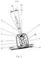
- FIG. 1 shows a selection device according to the invention for an automatic transmission of a motor vehicle.
- a selector lever 2 with a cross piece 3 is mounted on a cross piece pivot axis 5 in a housing 1 fixed to the body.
- the cross piece pivot axis 5 is in turn received in bearing bushes 5.1 and 5.2 in the housing 1.
- the selector lever 2 passes through the cross piece 3 in the axial direction and is mounted on a pin 4 in the cross piece 3.
- the bolt 4 is arranged orthogonally and spatially offset from the cross piece pivot axis 5.
- the selector lever 2 In its lower area, facing away from the vehicle driver, the selector lever 2 has a slide 7 supported by a compression spring 6 with locking rollers 8 attached to it.
- the locking rollers 8 are in contact with a sliding surface 9 in an arcuate region of the cross piece 3.
- a pawl 12 which is supported by compression springs 10 on the crosspiece 3 and can be pivoted about an axis 11.
- this pawl 12 is designed with two legs and takes up part of the arcuate region of the cross piece 3 between its legs.
- the compression springs 10 of the pawl 12 are very soft, that is to say they have a low spring stiffness
- the pawl 12 in turn consists of a linearly rising area which merges into a cam-like area, so that the locking rollers 8 for selecting the reverse gear one must overcome top dead center "before the pawl engages and thus fixes the selector lever 2. Since the spring 10 has a low spring stiffness, the geometry of the pawl 12, in particular of the cam-like area, must be designed so that the selector lever 2 is held in the reverse gear position.
- a roll holder 14 which is supported by a compression spring 13 and which receives a roll 15, is also provided.
- the roller 15 interacts with a profiled surface of a link 16, which in the present case is simultaneously designed as a lower housing part, and thus forms a detent. This ensures that the selector lever 2 during the selection of the Forward gears "in a first defined alley G1 and for the selection of the Reverse gear "can be positioned in a second defined alley G2, as can also be seen from FIG .
- the backdrop 16 has a double function in a selection device according to the invention. On the one hand, it is provided with the profiled surface described above to enable the selector lever 2 to be latched, and on the other hand the lower end of the selector lever 2 is guided in the link 16. By appropriate design of the scenery 16 it is achieved that the reverse gear can only be selected in the alley G2 assigned to it. From the illustration in Figure 2 it can also be seen that the slider 7 is resiliently supported against the selector lever 2 and two shaving rollers are laterally attached to the slider 7, which on movement of the selector lever 2 from its neutral position on the sliding surface 9 of the arcuate area the cross piece 3 roll off. In the embodiment in the drawing, only the movement of the selector lever 2 approximately in the vehicle longitudinal direction is possible as the selection direction.
- the selector lever 2 is mounted on the pin 4 in the cross piece 3.
- the central pin axis of the pin 4 lies above the cross piece pivot axis 5.
- the selector lever 2 In the basic position, the selector lever 2 is in alley G1 in the position labeled 0. To select the speed levels, the selector lever 2 is swiveled around the pin 4 in the crosspiece 3 in taps. The locking rollers 8 slide or roll on the sliding surface 9, which due to its rising design causes the selector lever 2 to return to the initial position 0 after being tapped. The selector lever 2 is guided with its lower end in a backdrop 16. Due to the design of the backdrop 16, the detent rollers 8 cannot press the pawl 12 so far when the selector lever 2 is moved in the alley G1 in the direction H that it engages.
- the driver swivels the selector lever 2 out of position 0 together with the cross piece 3 about the cross piece pivot axis 5 into the second alley G2, the spring-supported roller 15 together with the defined profiled surface of the link 16 ensuring that at the same time forms the lower housing part, so that the selector lever 2 is locked in this alley G2.
- the vehicle driver can now engage reverse gear by pivoting the selector lever 2 around the bolt 4, the locking rollers 8 slide on the sliding surface 9 over the pawl 12 to the locking position R.
- the pawl 12 consists of a linearly rising area which merges into a cam-like area, so that the locking rollers 8 to select the reverse gear first one must overcome top dead center "before the pawl engages and thus fixes the selector lever 2.
- the invention In order to move the selector lever 2 out of the locking position R, the invention must be used a noticeably greater force is exerted on the selector lever 2 than is the case with the gear steps is the case for forward travel.
- the selector lever 2 is out of the locking position R. pivoted about the bolt 4 back to position 0, he first the must overcome cam-like area of the pawl.
- the locking lugs 8 press on the Pawl 12, this is pivoted about the axis 11, the compression springs 10 opposing their direction of action.
- the locking rollers 8 of the slide 7 of the Selector lever 2 returns this to position 0, but in alley G2.
- the driver In order to be able to drive forward again, the driver must use the selector lever 2 with the Swivel cross piece 3 into alley G1.
- the role 15 causes the Selector lever 2 remains in this alley G1.
- the presented electronically controlled automatic circuit for transmissions of motor vehicles according to the invention offers a high level of comfort, since no noise or vibrations of the transmission, as is the case, for example, with linkages or cables, are transmitted via the selector lever, but only the position of the selector lever, for example, is detected by sensors and forwarded to the transmission. That well-known to the machine operator Shift feeling "is simulated.
Landscapes
- Engineering & Computer Science (AREA)
- General Engineering & Computer Science (AREA)
- Mechanical Engineering (AREA)
- Arrangement Or Mounting Of Control Devices For Change-Speed Gearing (AREA)
- Control Of Transmission Device (AREA)
- Gear-Shifting Mechanisms (AREA)
Applications Claiming Priority (2)
| Application Number | Priority Date | Filing Date | Title |
|---|---|---|---|
| DE19637254A DE19637254C2 (de) | 1996-09-13 | 1996-09-13 | Wählvorrichtung für ein Automatikgetriebe von Kraftfahrzeugen |
| DE19637254 | 1996-09-13 |
Publications (3)
| Publication Number | Publication Date |
|---|---|
| EP0837266A2 true EP0837266A2 (fr) | 1998-04-22 |
| EP0837266A3 EP0837266A3 (fr) | 2000-01-19 |
| EP0837266B1 EP0837266B1 (fr) | 2002-03-06 |
Family
ID=7805482
Family Applications (1)
| Application Number | Title | Priority Date | Filing Date |
|---|---|---|---|
| EP97115703A Expired - Lifetime EP0837266B1 (fr) | 1996-09-13 | 1997-09-10 | Dispositif de sélection pour une transmission automatique d'un véhicule |
Country Status (4)
| Country | Link |
|---|---|
| US (1) | US5934145A (fr) |
| EP (1) | EP0837266B1 (fr) |
| DE (1) | DE19637254C2 (fr) |
| ES (1) | ES2172724T3 (fr) |
Cited By (1)
| Publication number | Priority date | Publication date | Assignee | Title |
|---|---|---|---|---|
| EP1531290A3 (fr) * | 2003-11-13 | 2010-09-22 | ZF FRIEDRICHSHAFEN Aktiengesellschaft | Dispositif de sélection de vitesse |
Families Citing this family (15)
| Publication number | Priority date | Publication date | Assignee | Title |
|---|---|---|---|---|
| DE19918509C2 (de) * | 1999-04-23 | 2002-04-25 | Daimler Chrysler Ag | Schaltvorrichtung |
| DE10003796C2 (de) * | 2000-01-28 | 2002-05-02 | Zf Lemfoerder Metallwaren Ag | Schaltvorrichtung für ein Automatikgetriebe eines Kraftfahrzeuges |
| USPP15990P3 (en) * | 2003-04-23 | 2005-09-20 | J. C. Bakker & Sons Limited | Lilac plant named ‘Golden Eclipse’ |
| US7221248B2 (en) * | 2003-05-15 | 2007-05-22 | Grand Haven Stamped Products | Solenoid with noise reduction |
| US7393304B2 (en) | 2003-05-15 | 2008-07-01 | Grand Haven Stamped Products | Shifter with gear position indicator |
| US7568404B2 (en) | 2004-07-26 | 2009-08-04 | Ghsp, A Division Of Jsj Corporation | Shifter having neutral lock |
| US7328782B2 (en) * | 2004-07-26 | 2008-02-12 | Grand Haven Stamped Products Company, A Division Of Jsj Corporation | Vehicle shifter with powered pawl having neutral lock |
| US8371188B2 (en) * | 2008-10-02 | 2013-02-12 | Kongsberg Driveline Systems I, Inc. | Transmission control assembly having a locking mechanism |
| JP5039188B2 (ja) * | 2010-08-20 | 2012-10-03 | アイシン・エーアイ株式会社 | 自動車用手動変速機のシフト装置 |
| CN102425656A (zh) * | 2011-10-14 | 2012-04-25 | 奇瑞汽车股份有限公司 | 一种换挡手柄连接结构 |
| EP2581629B1 (fr) * | 2012-03-22 | 2014-06-04 | Kongsberg Automotive AB | Ensemble sélecteur de vitesses avec un jeu réduit |
| DE102015201974A1 (de) * | 2015-02-05 | 2016-08-11 | Zf Friedrichshafen Ag | Verfahren und Vorrichtung zum Herstellen eines Lagerelements einer Schaltvorrichtung für ein Fahrzeuggetriebe sowie Lagerelement und Schaltvorrichtung für ein Fahrzeuggetriebe |
| CN105065657B (zh) * | 2015-08-20 | 2017-06-20 | 清河县科超汽车配件有限公司 | 一种电动操纵器 |
| JP7363711B2 (ja) | 2020-08-07 | 2023-10-18 | トヨタ自動車株式会社 | 電気自動車 |
| US11921536B2 (en) * | 2022-01-26 | 2024-03-05 | Woodward, Inc. | Soft stop force gradient for control stick |
Family Cites Families (13)
| Publication number | Priority date | Publication date | Assignee | Title |
|---|---|---|---|---|
| FR2256521B1 (fr) * | 1973-12-26 | 1976-10-08 | Telemecanique Electrique | |
| US3941008A (en) * | 1974-07-01 | 1976-03-02 | Hurst Performance, Inc. | Shift mechanism for automatic transmission |
| US4912997A (en) * | 1989-06-02 | 1990-04-03 | Chrysler Corporation | Electric shift selector mechanism for transmission |
| JPH0751625Y2 (ja) * | 1990-06-18 | 1995-11-22 | 京セラ株式会社 | ジョイスティック |
| DE4029330A1 (de) * | 1990-09-15 | 1992-03-26 | Porsche Ag | Schaltvorrichtung fuer ein kraftfahrzeuggetriebe |
| JPH05312248A (ja) * | 1992-05-08 | 1993-11-22 | Nissan Motor Co Ltd | シフトレバー装置 |
| US5277078A (en) * | 1992-10-26 | 1994-01-11 | Grand Haven Stamped Products, Div. Of Jsj Corporation | Vehicle shifter with roller and detent type shift lever positioner |
| JP2594960Y2 (ja) * | 1993-01-29 | 1999-05-24 | 富士機工株式会社 | 自動変速機操作装置のチェック機構 |
| FR2703958B1 (fr) * | 1993-04-13 | 1995-07-13 | Jaeger | Ensemble de commande pour boite de vitesses mecanique et systeme de commande incorporant celui-ci. |
| DE4311924A1 (de) * | 1993-04-14 | 1994-10-20 | Hilti Ag | Tragvorrichtung |
| JP2864322B2 (ja) * | 1993-05-11 | 1999-03-03 | 株式会社アツミテック | 自動変速機用シフト装置 |
| US5551266A (en) * | 1995-05-22 | 1996-09-03 | Chrysler Corporation | Manual transmission shifter to ignition interlock |
| DE19526059C2 (de) * | 1995-07-17 | 1999-05-27 | Lemfoerder Metallwaren Ag | Schaltvorrichtung für ein automatisches Getriebe eines Kraftfahrzeugs |
-
1996
- 1996-09-13 DE DE19637254A patent/DE19637254C2/de not_active Expired - Fee Related
-
1997
- 1997-09-10 ES ES97115703T patent/ES2172724T3/es not_active Expired - Lifetime
- 1997-09-10 EP EP97115703A patent/EP0837266B1/fr not_active Expired - Lifetime
- 1997-09-12 US US08/928,374 patent/US5934145A/en not_active Expired - Fee Related
Cited By (1)
| Publication number | Priority date | Publication date | Assignee | Title |
|---|---|---|---|---|
| EP1531290A3 (fr) * | 2003-11-13 | 2010-09-22 | ZF FRIEDRICHSHAFEN Aktiengesellschaft | Dispositif de sélection de vitesse |
Also Published As
| Publication number | Publication date |
|---|---|
| DE19637254C2 (de) | 1998-07-30 |
| DE19637254A1 (de) | 1998-03-19 |
| ES2172724T3 (es) | 2002-10-01 |
| EP0837266A3 (fr) | 2000-01-19 |
| EP0837266B1 (fr) | 2002-03-06 |
| US5934145A (en) | 1999-08-10 |
Similar Documents
| Publication | Publication Date | Title |
|---|---|---|
| EP0693391B1 (fr) | Dispositif de sélection pour une boíte de vitesses automatique d'un véhicule automobile | |
| DE19549437C2 (de) | Schaltvorrichtung für ein automatisches Getriebe eines Kraftfahrzeugs | |
| EP0794362B1 (fr) | Mécanisme de sélection de rapport pour une transmission | |
| EP0837266B1 (fr) | Dispositif de sélection pour une transmission automatique d'un véhicule | |
| EP1984655B1 (fr) | Dispositif de changement de vitesse pour une boîte de vitesses de vehicule automobile | |
| EP0825364B1 (fr) | Dispositif de sélection pour boíte de vitesses automatique de véhicule automobile | |
| DE2062691A1 (de) | Schaltvorrichtung eines Zahnräderwechselgetriebes, insbesondere für Kraftfahrzeuge | |
| DE69722364T2 (de) | Schaltsperreinrichtung für Schalthebel | |
| EP0699853B1 (fr) | Tringlerie de sélection des vitesses pour boîte de vitesse d'un véhicule | |
| DE10315643B3 (de) | Shift by wire-Schaltung mit P-Position | |
| DE3439161A1 (de) | Getriebesteuerung | |
| EP0809046A2 (fr) | Dispositif de changement de vitesse pour une transmission automatique d'un véhicule automobile | |
| DE19756034A1 (de) | Wählvorrichtung für ein Fahrzeuggetriebe | |
| EP1554509A1 (fr) | Dispositif de passage de vitesses destine a une transmission automatique | |
| DE102008022561B4 (de) | Schaltvorrichtung für ein Automatikgetriebe | |
| DE2949328A1 (de) | Anzeigevorrichtung fuer die schaltstellung eines wechselgetriebes fuer kraftfahrzeuge | |
| EP1267240B1 (fr) | Changement de vitesse pour une boíte de vitesses manuelle d'un véhicule automobile | |
| DE4446079A1 (de) | Schalteinrichtung für ein Kraftfahrzeug mit einem automatischen Getriebe | |
| DE4428205A1 (de) | Betätigungseinrichtung zum Steuern des Gangwechsels eines Getriebes für ein Kraftfahrzeug | |
| DE102008022447B4 (de) | Schaltvorrichtung für ein Automatikgetriebe | |
| DE19737366A1 (de) | Schaltvorrichtung für Automatikgetriebe | |
| DE19620532A1 (de) | Schaltvorrichtung für ein Automatikgetriebe eines Kraftfahrzeuges | |
| DE19735290A1 (de) | Schaltvorrichtung | |
| DE10163605C1 (de) | Wähleinrichtung für ein Schaltgetriebe | |
| EP0849507A2 (fr) | Tringlerie de changement de vitesses pour la transmission des efforts de selection |
Legal Events
| Date | Code | Title | Description |
|---|---|---|---|
| PUAI | Public reference made under article 153(3) epc to a published international application that has entered the european phase |
Free format text: ORIGINAL CODE: 0009012 |
|
| AK | Designated contracting states |
Kind code of ref document: A2 Designated state(s): BE ES FR GB IT NL SE |
|
| AX | Request for extension of the european patent |
Free format text: AL;LT;LV;RO;SI |
|
| PUAL | Search report despatched |
Free format text: ORIGINAL CODE: 0009013 |
|
| AK | Designated contracting states |
Kind code of ref document: A3 Designated state(s): AT BE CH DE DK ES FI FR GB GR IE IT LI LU MC NL PT SE |
|
| AX | Request for extension of the european patent |
Free format text: AL;LT;LV;RO;SI |
|
| RIC1 | Information provided on ipc code assigned before grant |
Free format text: 7F 16H 59/04 A, 7F 16H 59/10 B |
|
| 17P | Request for examination filed |
Effective date: 20000225 |
|
| RAP1 | Party data changed (applicant data changed or rights of an application transferred) |
Owner name: ZF LEMFOERDER METALLWAREN AG |
|
| AKX | Designation fees paid |
Free format text: BE ES FR GB IT NL SE |
|
| REG | Reference to a national code |
Ref country code: DE Ref legal event code: 8566 |
|
| GRAG | Despatch of communication of intention to grant |
Free format text: ORIGINAL CODE: EPIDOS AGRA |
|
| GRAG | Despatch of communication of intention to grant |
Free format text: ORIGINAL CODE: EPIDOS AGRA |
|
| GRAH | Despatch of communication of intention to grant a patent |
Free format text: ORIGINAL CODE: EPIDOS IGRA |
|
| 17Q | First examination report despatched |
Effective date: 20010725 |
|
| GRAH | Despatch of communication of intention to grant a patent |
Free format text: ORIGINAL CODE: EPIDOS IGRA |
|
| REG | Reference to a national code |
Ref country code: GB Ref legal event code: IF02 |
|
| GRAA | (expected) grant |
Free format text: ORIGINAL CODE: 0009210 |
|
| RIN1 | Information on inventor provided before grant (corrected) |
Inventor name: KALZ, WOLFGANG Inventor name: TIEMEYER, DETLEV Inventor name: ERSOY, METIN, DR. |
|
| AK | Designated contracting states |
Kind code of ref document: B1 Designated state(s): BE ES FR GB IT NL SE |
|
| GBT | Gb: translation of ep patent filed (gb section 77(6)(a)/1977) |
Effective date: 20020306 |
|
| ET | Fr: translation filed | ||
| REG | Reference to a national code |
Ref country code: ES Ref legal event code: FG2A Ref document number: 2172724 Country of ref document: ES Kind code of ref document: T3 |
|
| PLBE | No opposition filed within time limit |
Free format text: ORIGINAL CODE: 0009261 |
|
| STAA | Information on the status of an ep patent application or granted ep patent |
Free format text: STATUS: NO OPPOSITION FILED WITHIN TIME LIMIT |
|
| 26N | No opposition filed |
Effective date: 20021209 |
|
| PGFP | Annual fee paid to national office [announced via postgrant information from national office to epo] |
Ref country code: NL Payment date: 20080903 Year of fee payment: 12 |
|
| PGFP | Annual fee paid to national office [announced via postgrant information from national office to epo] |
Ref country code: SE Payment date: 20090910 Year of fee payment: 13 Ref country code: GB Payment date: 20090909 Year of fee payment: 13 |
|
| PGFP | Annual fee paid to national office [announced via postgrant information from national office to epo] |
Ref country code: ES Payment date: 20091006 Year of fee payment: 13 |
|
| PGFP | Annual fee paid to national office [announced via postgrant information from national office to epo] |
Ref country code: BE Payment date: 20090917 Year of fee payment: 13 |
|
| REG | Reference to a national code |
Ref country code: NL Ref legal event code: V1 Effective date: 20100401 |
|
| PGFP | Annual fee paid to national office [announced via postgrant information from national office to epo] |
Ref country code: IT Payment date: 20090915 Year of fee payment: 13 Ref country code: FR Payment date: 20091012 Year of fee payment: 13 |
|
| PG25 | Lapsed in a contracting state [announced via postgrant information from national office to epo] |
Ref country code: NL Free format text: LAPSE BECAUSE OF NON-PAYMENT OF DUE FEES Effective date: 20100401 |
|
| BERE | Be: lapsed |
Owner name: *ZF LEMFORDER METALLWAREN A.G. Effective date: 20100930 |
|
| REG | Reference to a national code |
Ref country code: SE Ref legal event code: EUG |
|
| GBPC | Gb: european patent ceased through non-payment of renewal fee |
Effective date: 20100910 |
|
| PG25 | Lapsed in a contracting state [announced via postgrant information from national office to epo] |
Ref country code: IT Free format text: LAPSE BECAUSE OF NON-PAYMENT OF DUE FEES Effective date: 20100910 |
|
| REG | Reference to a national code |
Ref country code: FR Ref legal event code: ST Effective date: 20110531 |
|
| PG25 | Lapsed in a contracting state [announced via postgrant information from national office to epo] |
Ref country code: BE Free format text: LAPSE BECAUSE OF NON-PAYMENT OF DUE FEES Effective date: 20100930 Ref country code: FR Free format text: LAPSE BECAUSE OF NON-PAYMENT OF DUE FEES Effective date: 20100930 |
|
| PG25 | Lapsed in a contracting state [announced via postgrant information from national office to epo] |
Ref country code: GB Free format text: LAPSE BECAUSE OF NON-PAYMENT OF DUE FEES Effective date: 20100910 |
|
| REG | Reference to a national code |
Ref country code: ES Ref legal event code: FD2A Effective date: 20111019 |
|
| PG25 | Lapsed in a contracting state [announced via postgrant information from national office to epo] |
Ref country code: ES Free format text: LAPSE BECAUSE OF NON-PAYMENT OF DUE FEES Effective date: 20100911 |
|
| PG25 | Lapsed in a contracting state [announced via postgrant information from national office to epo] |
Ref country code: SE Free format text: LAPSE BECAUSE OF NON-PAYMENT OF DUE FEES Effective date: 20100911 |