EP0837357A2 - Procédé et dispositif de modulation de la lumière - Google Patents
Procédé et dispositif de modulation de la lumière Download PDFInfo
- Publication number
- EP0837357A2 EP0837357A2 EP97117713A EP97117713A EP0837357A2 EP 0837357 A2 EP0837357 A2 EP 0837357A2 EP 97117713 A EP97117713 A EP 97117713A EP 97117713 A EP97117713 A EP 97117713A EP 0837357 A2 EP0837357 A2 EP 0837357A2
- Authority
- EP
- European Patent Office
- Prior art keywords
- light beam
- light
- dispersive medium
- exit
- frequency
- Prior art date
- Legal status (The legal status is an assumption and is not a legal conclusion. Google has not performed a legal analysis and makes no representation as to the accuracy of the status listed.)
- Withdrawn
Links
- 238000000034 method Methods 0.000 title claims abstract description 26
- 230000009021 linear effect Effects 0.000 claims abstract description 8
- 230000003287 optical effect Effects 0.000 claims abstract description 8
- 230000001419 dependent effect Effects 0.000 claims abstract description 6
- 239000003365 glass fiber Substances 0.000 claims description 16
- 239000003086 colorant Substances 0.000 claims description 6
- 239000000463 material Substances 0.000 claims description 6
- XUIMIQQOPSSXEZ-UHFFFAOYSA-N Silicon Chemical compound [Si] XUIMIQQOPSSXEZ-UHFFFAOYSA-N 0.000 claims description 5
- 229910052710 silicon Inorganic materials 0.000 claims description 5
- 239000010703 silicon Substances 0.000 claims description 5
- 238000012937 correction Methods 0.000 claims description 4
- 230000005684 electric field Effects 0.000 claims description 4
- 238000005530 etching Methods 0.000 claims description 4
- 238000005204 segregation Methods 0.000 claims description 4
- JRPBQTZRNDNNOP-UHFFFAOYSA-N barium titanate Chemical compound [Ba+2].[Ba+2].[O-][Ti]([O-])([O-])[O-] JRPBQTZRNDNNOP-UHFFFAOYSA-N 0.000 claims description 3
- 229910002113 barium titanate Inorganic materials 0.000 claims description 3
- JBRZTFJDHDCESZ-UHFFFAOYSA-N AsGa Chemical compound [As]#[Ga] JBRZTFJDHDCESZ-UHFFFAOYSA-N 0.000 claims description 2
- 229910001218 Gallium arsenide Inorganic materials 0.000 claims description 2
- GQYHUHYESMUTHG-UHFFFAOYSA-N lithium niobate Chemical compound [Li+].[O-][Nb](=O)=O GQYHUHYESMUTHG-UHFFFAOYSA-N 0.000 claims description 2
- HCDCUCIGHWMYFX-UHFFFAOYSA-N n-cyclooctyl-5-nitropyridin-2-amine Chemical compound N1=CC([N+](=O)[O-])=CC=C1NC1CCCCCCC1 HCDCUCIGHWMYFX-UHFFFAOYSA-N 0.000 claims description 2
- 239000013078 crystal Substances 0.000 description 15
- 239000000835 fiber Substances 0.000 description 2
- 230000005540 biological transmission Effects 0.000 description 1
- 230000005670 electromagnetic radiation Effects 0.000 description 1
- 238000001914 filtration Methods 0.000 description 1
- 230000010365 information processing Effects 0.000 description 1
- 239000000203 mixture Substances 0.000 description 1
- 230000009022 nonlinear effect Effects 0.000 description 1
- 239000013307 optical fiber Substances 0.000 description 1
Images
Classifications
-
- G—PHYSICS
- G01—MEASURING; TESTING
- G01J—MEASUREMENT OF INTENSITY, VELOCITY, SPECTRAL CONTENT, POLARISATION, PHASE OR PULSE CHARACTERISTICS OF INFRARED, VISIBLE OR ULTRAVIOLET LIGHT; COLORIMETRY; RADIATION PYROMETRY
- G01J3/00—Spectrometry; Spectrophotometry; Monochromators; Measuring colours
- G01J3/12—Generating the spectrum; Monochromators
- G01J3/14—Generating the spectrum; Monochromators using refracting elements, e.g. prisms
-
- G—PHYSICS
- G02—OPTICS
- G02F—OPTICAL DEVICES OR ARRANGEMENTS FOR THE CONTROL OF LIGHT BY MODIFICATION OF THE OPTICAL PROPERTIES OF THE MEDIA OF THE ELEMENTS INVOLVED THEREIN; NON-LINEAR OPTICS; FREQUENCY-CHANGING OF LIGHT; OPTICAL LOGIC ELEMENTS; OPTICAL ANALOGUE/DIGITAL CONVERTERS
- G02F1/00—Devices or arrangements for the control of the intensity, colour, phase, polarisation or direction of light arriving from an independent light source, e.g. switching, gating or modulating; Non-linear optics
- G02F1/01—Devices or arrangements for the control of the intensity, colour, phase, polarisation or direction of light arriving from an independent light source, e.g. switching, gating or modulating; Non-linear optics for the control of the intensity, phase, polarisation or colour
- G02F1/23—Devices or arrangements for the control of the intensity, colour, phase, polarisation or direction of light arriving from an independent light source, e.g. switching, gating or modulating; Non-linear optics for the control of the intensity, phase, polarisation or colour for the control of the colour
-
- G—PHYSICS
- G02—OPTICS
- G02F—OPTICAL DEVICES OR ARRANGEMENTS FOR THE CONTROL OF LIGHT BY MODIFICATION OF THE OPTICAL PROPERTIES OF THE MEDIA OF THE ELEMENTS INVOLVED THEREIN; NON-LINEAR OPTICS; FREQUENCY-CHANGING OF LIGHT; OPTICAL LOGIC ELEMENTS; OPTICAL ANALOGUE/DIGITAL CONVERTERS
- G02F1/00—Devices or arrangements for the control of the intensity, colour, phase, polarisation or direction of light arriving from an independent light source, e.g. switching, gating or modulating; Non-linear optics
- G02F1/29—Devices or arrangements for the control of the intensity, colour, phase, polarisation or direction of light arriving from an independent light source, e.g. switching, gating or modulating; Non-linear optics for the control of the position or the direction of light beams, i.e. deflection
- G02F1/293—Devices or arrangements for the control of the intensity, colour, phase, polarisation or direction of light arriving from an independent light source, e.g. switching, gating or modulating; Non-linear optics for the control of the position or the direction of light beams, i.e. deflection by another light beam, i.e. opto-optical deflection
-
- G—PHYSICS
- G02—OPTICS
- G02F—OPTICAL DEVICES OR ARRANGEMENTS FOR THE CONTROL OF LIGHT BY MODIFICATION OF THE OPTICAL PROPERTIES OF THE MEDIA OF THE ELEMENTS INVOLVED THEREIN; NON-LINEAR OPTICS; FREQUENCY-CHANGING OF LIGHT; OPTICAL LOGIC ELEMENTS; OPTICAL ANALOGUE/DIGITAL CONVERTERS
- G02F1/00—Devices or arrangements for the control of the intensity, colour, phase, polarisation or direction of light arriving from an independent light source, e.g. switching, gating or modulating; Non-linear optics
- G02F1/35—Non-linear optics
- G02F1/355—Non-linear optics characterised by the materials used
Definitions
- the invention relates to a method and an apparatus for Modulating light, especially for amplifying, filtering and / or analyzing light and / or for switching by means of Light.
- materials are known whose refractive index is not is only different for different colored light, but by an incident first beam of light for another Light beam actually due to non-linear effects is variable. For example, one is when irradiated so-called photorefractive material with a light beam a first wavelength and a light beam of a second Wavelength the refractive index for the light beam of the second Wavelength different from that which would exist if only the light beam of the second wavelength would strike.
- the object of the invention is a method and an apparatus for easy and fast modulation of light.
- a method for modulating light in which a first light beam comprising at least one comprising the first light beam and a second light beam at least a second light beam in a dispersive medium occur with non-linear optical behavior and at least a third light beam from the dispersive medium emerges, the refractive index of the dispersive medium by the on / off time, the frequency and / or the amplitude of the at least one first light beam varies and thus that second light bundle for forming the third light beam after Passing through the dispersive medium in its amplitude, its frequency, its exit location and / or its exit direction is modulated.
- the invention can further provide that the second light rays, preferably pulsed individually.
- the second light beams can run parallel to one another.
- the invention also proposes that a first light beam monochromatic light beam is used.
- a third beam of light can also act as monochromatic light are generated according to the invention.
- a further development according to the invention is characterized in that that about the exit location and / or the exit direction for a third light beam its color, possibly selected according to that of the first light beam becomes.
- the invention further proposes that by modulating of the second light bundle the same over the at least one third light beam is analyzed.
- the modulation of one is influenced from the outside field.
- an electrical Field, a magnetic field and / or a distortion field is applied to the dispersive medium.
- the invention proposes that the arrangement of the dispersive medium relative to the first light beam, the second light beam and the at least one third light beam is determined in an etching process.
- the invention proposes that to avoid a Color distortion the first light beam, the second light beam and / or the at least one third light beam continuously at a certain light intensity level, preferably each time held by at least one regulator.
- a device for modulating light in particular using a method according to the invention, comprising a dispersive medium which is a non-linear has optical behavior and between a first Light bundle, comprising at least a first light beam, with which the refractive index of the dispersive medium can be varied and a second light beam comprising at least one second light beam is arranged so that at least one third light beam emerging from the dispersive medium depends on the refractive index of the second light beam in Amplitude, frequency, exit location and / or exit direction differs, solved.
- the dispersive medium includes photorefractive material.
- the photorefractive Material silicon, gallium arsenide, lithium niobate, Doped barium titanate or 2-cyclooctylamino-5-nitropyridine with 7,7,8,8-tetrazyanoquinodimethane is preferred.
- the invention also proposes that a light guide for first and / or second light bundles each have at least one glass fiber includes.
- each first and / or second light beam is a laser beam.
- the invention also proposes that the second light beam several monochromatic, preferably parallel to each other extending second light beams.
- the on / off time of the second Light rays is adjustable.
- the dispersive Medium is an electric field, a magnetic field and / or a distortion field to influence the non-linear Behavior of the same, at least temporarily, can be created is.
- the invention proposes that the arrangement for the dispersive medium and light guide produced in an etching process is.
- An embodiment according to the invention is characterized in that that an amplifier is provided, the second light beam has a higher intensity than the first light beam has and the at least a third light beam has the same color as the first light beam.
- an n-way switch and / or color switches and / or an OR gate and / or a filter be provided depending on the Amplitude and / or frequency of the third light beam on one selected exit location, possibly with a selected one Exit direction, works.
- the n-way switch is an on-off switch is.
- Another embodiment of the invention is characterized in that that a light transmitter is provided, wherein the second light beam over several second light beams comprises several frequencies and the frequency (s) of the at least a third light beam over its exit location and / or the exit direction is adjustable.
- the third light beam, the second light beam can be analyzed.
- the device can also be an optical one System, in particular a lens system, over which to avoid color segregation by frequency-dependent Velocity of light outside the dispersive medium Corrections can be made.
- the invention proposes that in the first light beam, the second light beam and / or the at least one third light beam provided at least one regulator is continuous to avoid color distortion regulates to a certain light intensity level.
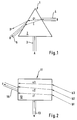
- the core of the light amplifier and switch 1 is a crystal 2, for example made of silicon, on which two light beams A and B of the same wavelength each strike via a glass fiber 3 or 4.
- the beam path of the first light beam A is only shown until it enters the single crystal 2, while the beam path of the second light beam B is identified in the single crystal 2 with C or C ' and after passing through it with D or D ' .
- the second light beam B is refracted due to the refractive index of the crystal 2 influenced by the first light beam A into the third light beam D via the light beam C, which propagates in a glass fiber 5. However, if no first light beam A strikes the crystal 2, the refractive index of the crystal 2 is not changed and the second light beam B is refracted into the light beam D 'via the light beam C'.
- the device 1 functions as a light amplifier and switch in principle like a transistor, the glass fiber 3 being the BASE connection, the glass fiber 4 being the COLLECTOR connection and the glass fiber 5 being the EMITTER connection.
- the first light beam A enters the single crystal 2
- its refractive index changes, so that then the second light beam B, which is of the same color but has a higher intensity than the first light beam, instead of the light beam D ' into the third Light beam D is refracted to get into the third glass fiber 5.
- Fig. 2 shows a light transmitter 11, the core of which in turn is a crystal 12, for example made of barium titanate, in the a first light beam a via an optical fiber 13 Modulation purposes occurs.
- light beam a is not for the sake of clarity emerging from and emerging from crystal 12 shown.
- a beam of light also enters crystal 12 of three monochromatic, parallel to each other second light beams b1, b2 and b3 with different frequencies, in three basic colors, one.
- the second rays of light b1, b2 and b3 are a adjustable refractive index of crystal 12 in three Light rays c1, c2 and c3 when entering crystal 12 Broken.
- These three light beams c1, c2 and c3 are used in the Exit from the crystal 12 in three light rays, not shown broken, so that in a fiber 15 a third Beam of light d arises, the color and intensity of which vary according to the exit location specified by the arrangement of the glass fiber 15 and default exit direction for the third light beam d, from the three primary colors of the third Light rays b1, b2 and b3 or their intensities.
- the light transmitter 11 thus essentially provides a color mixer represents that of the three monochromatic second light rays b1, b2 and b3 when using a particular first A desired, variable color mixture for generates the third light beam d.
Landscapes
- Physics & Mathematics (AREA)
- Nonlinear Science (AREA)
- General Physics & Mathematics (AREA)
- Optics & Photonics (AREA)
- Spectroscopy & Molecular Physics (AREA)
- Optical Modulation, Optical Deflection, Nonlinear Optics, Optical Demodulation, Optical Logic Elements (AREA)
- Lasers (AREA)
Applications Claiming Priority (2)
| Application Number | Priority Date | Filing Date | Title |
|---|---|---|---|
| DE19642904 | 1996-10-17 | ||
| DE1996142904 DE19642904C2 (de) | 1996-10-17 | 1996-10-17 | Vorrichtung zum Modulieren von Licht |
Publications (2)
| Publication Number | Publication Date |
|---|---|
| EP0837357A2 true EP0837357A2 (fr) | 1998-04-22 |
| EP0837357A3 EP0837357A3 (fr) | 1999-03-17 |
Family
ID=7809043
Family Applications (1)
| Application Number | Title | Priority Date | Filing Date |
|---|---|---|---|
| EP97117713A Withdrawn EP0837357A3 (fr) | 1996-10-17 | 1997-10-13 | Procédé et dispositif de modulation de la lumière |
Country Status (2)
| Country | Link |
|---|---|
| EP (1) | EP0837357A3 (fr) |
| DE (1) | DE19642904C2 (fr) |
Families Citing this family (1)
| Publication number | Priority date | Publication date | Assignee | Title |
|---|---|---|---|---|
| DE102006004026A1 (de) * | 2006-01-27 | 2007-06-06 | Siemens Ag | Optischer Schalter |
Family Cites Families (10)
| Publication number | Priority date | Publication date | Assignee | Title |
|---|---|---|---|---|
| US3305292A (en) * | 1963-03-15 | 1967-02-21 | Rca Corp | Light deflecting device |
| US4880296A (en) * | 1987-06-04 | 1989-11-14 | The United States Of America As Represented By The Secretary Of The Navy | Opto-optical bean deflector, modulator, and shaper |
| US4846540A (en) * | 1988-01-25 | 1989-07-11 | Bell Communications Research, Inc. | Optical wavegide junction |
| US5150248A (en) * | 1989-07-21 | 1992-09-22 | Alfano Robert R | Terahertz repetition rate optical computing systems, and communication systems and logic elements using cross-phase modulation based optical processors |
| DE4008544A1 (de) * | 1990-01-22 | 1991-07-25 | Siemens Ag | Vorrichtung zur optischen frequenzumschaltung, insbesondere fuer optische vielkanal-vermittlungssysteme ohne optoelektronische wandlung |
| JPH03228032A (ja) * | 1990-02-01 | 1991-10-09 | Mitsubishi Electric Corp | 光方向性結合器 |
| US5126874A (en) * | 1990-07-11 | 1992-06-30 | Alfano Robert R | Method and apparatus for creating transient optical elements and circuits |
| US5216535A (en) * | 1991-06-17 | 1993-06-01 | Fellows William G | Optical deflection device |
| DE4225900A1 (de) * | 1992-08-05 | 1994-02-10 | Roland Dr Schiek | Verfahren zur Beeinflussung und Steuerung der räumlichen und zeitlichen Lichtausbreitung in optischen und elektrooptischen Bauelementen durch Licht |
| JPH07140499A (ja) * | 1993-11-22 | 1995-06-02 | Nippon Telegr & Teleph Corp <Ntt> | 有機フォトリフラクティブ媒体の書き込み方法及び有機フォトリフラクティブ媒体 |
-
1996
- 1996-10-17 DE DE1996142904 patent/DE19642904C2/de not_active Expired - Fee Related
-
1997
- 1997-10-13 EP EP97117713A patent/EP0837357A3/fr not_active Withdrawn
Also Published As
| Publication number | Publication date |
|---|---|
| DE19642904A1 (de) | 1998-04-30 |
| DE19642904C2 (de) | 2003-10-30 |
| EP0837357A3 (fr) | 1999-03-17 |
Similar Documents
| Publication | Publication Date | Title |
|---|---|---|
| DE69034102T2 (de) | Anordnung einer optischen Faser mit variablem Braggfilter | |
| DE69411590T2 (de) | Methode und vorrichtung zur erzeugung von aperiodischen gittern in optischen fasern | |
| DE69021543T2 (de) | Umlenkende Bragg-Gitteranordnung in einem optischen Wellenleiter. | |
| DE4243057B4 (de) | Faseroptischer Leistungsteiler und -vereiniger | |
| DE69706726T2 (de) | Einrichtung zur optischen Signalformung für Anwendungen bei komplexen Spektral-formen | |
| DE69218903T2 (de) | Soliton-Generator | |
| DE3431448C2 (de) | Optische Demultiplex-Übertragungseinrichtung | |
| DE602004000098T2 (de) | Optische Wellenleiteranordnung mit reduzierten Überkreuzungsverlusten | |
| DE3413644A1 (de) | Lichtunterbrechungsstop fuer einen elektro-optischen zeilendrucker | |
| DE69021750T2 (de) | Verlustarme Wellenleiterkreuzung. | |
| DE2630530A1 (de) | Kopplungseinrichtung fuer eine glasfaserleitung | |
| DE3416493A1 (de) | Optische empfangseinrichtung | |
| DE3414724A1 (de) | Optischer multiplexer/demultiplexer | |
| DE2527939C2 (de) | Verfahren zum Betreiben eines ebenen Multimoden-Lichtwellenleiters | |
| DE1801284A1 (de) | Verfahren und Vorrichtung zur Aufbereitung von von einer Sendestelle auszusendenden Signalen mit Hilfe eines Laserstrahls | |
| DE69827070T2 (de) | Verfahren und Vorrichtung zur Herstellung von Bragg-Gittern in optischen Fasern oder Wellenleitern | |
| DE3781498T2 (de) | Optische vorrichtung. | |
| DE69933180T2 (de) | Optischer Inverter auf der Basis eines sättigbaren Absorbers | |
| DE3640920A1 (de) | Optisches multiplexsystem und verfahren zu seinem betrieb | |
| DE19630706A1 (de) | Optischer Verzweiger | |
| DE2220148A1 (de) | Abstimmbarer optischer Filter | |
| EP0837357A2 (fr) | Procédé et dispositif de modulation de la lumière | |
| DE2359797C3 (de) | Schaltbare optische Wellenleitereinrichtung | |
| DE2717412A1 (de) | Durchgangspruefgeraet fuer lichtleitfasern | |
| EP0786677A1 (fr) | Dispositif de couplage optique comprenant une paire de sections de guides d'ondes optiques en forme de rubans |
Legal Events
| Date | Code | Title | Description |
|---|---|---|---|
| PUAI | Public reference made under article 153(3) epc to a published international application that has entered the european phase |
Free format text: ORIGINAL CODE: 0009012 |
|
| AK | Designated contracting states |
Kind code of ref document: A2 Designated state(s): AT BE CH DE DK ES FI FR GB GR IE IT LI LU MC NL PT SE |
|
| AX | Request for extension of the european patent |
Free format text: AL;LT;LV;RO;SI |
|
| PUAL | Search report despatched |
Free format text: ORIGINAL CODE: 0009013 |
|
| AK | Designated contracting states |
Kind code of ref document: A3 Designated state(s): AT BE CH DE DK ES FI FR GB GR IE IT LI LU MC NL PT SE |
|
| AX | Request for extension of the european patent |
Free format text: AL;LT;LV;RO;SI |
|
| STAA | Information on the status of an ep patent application or granted ep patent |
Free format text: STATUS: THE APPLICATION HAS BEEN WITHDRAWN |
|
| 18W | Application withdrawn |
Withdrawal date: 19990917 |