EP0837536A2 - Dispositif d'entraínement pour masses à mouvement aller et retour, guidé longitudinalement - Google Patents
Dispositif d'entraínement pour masses à mouvement aller et retour, guidé longitudinalement Download PDFInfo
- Publication number
- EP0837536A2 EP0837536A2 EP97117980A EP97117980A EP0837536A2 EP 0837536 A2 EP0837536 A2 EP 0837536A2 EP 97117980 A EP97117980 A EP 97117980A EP 97117980 A EP97117980 A EP 97117980A EP 0837536 A2 EP0837536 A2 EP 0837536A2
- Authority
- EP
- European Patent Office
- Prior art keywords
- motor
- drive device
- control device
- temperature
- movable mass
- Prior art date
- Legal status (The legal status is an assumption and is not a legal conclusion. Google has not performed a legal analysis and makes no representation as to the accuracy of the status listed.)
- Granted
Links
Images

Classifications
-
- H—ELECTRICITY
- H02—GENERATION; CONVERSION OR DISTRIBUTION OF ELECTRIC POWER
- H02H—EMERGENCY PROTECTIVE CIRCUIT ARRANGEMENTS
- H02H7/00—Emergency protective circuit arrangements specially adapted for specific types of electric machines or apparatus or for sectionalised protection of cable or line systems, and effecting automatic switching in the event of an undesired change from normal working conditions
- H02H7/08—Emergency protective circuit arrangements specially adapted for specific types of electric machines or apparatus or for sectionalised protection of cable or line systems, and effecting automatic switching in the event of an undesired change from normal working conditions for dynamo-electric motors
- H02H7/085—Emergency protective circuit arrangements specially adapted for specific types of electric machines or apparatus or for sectionalised protection of cable or line systems, and effecting automatic switching in the event of an undesired change from normal working conditions for dynamo-electric motors against excessive load
- H02H7/0856—Emergency protective circuit arrangements specially adapted for specific types of electric machines or apparatus or for sectionalised protection of cable or line systems, and effecting automatic switching in the event of an undesired change from normal working conditions for dynamo-electric motors against excessive load characterised by the protection measure taken
- H02H7/0858—Emergency protective circuit arrangements specially adapted for specific types of electric machines or apparatus or for sectionalised protection of cable or line systems, and effecting automatic switching in the event of an undesired change from normal working conditions for dynamo-electric motors against excessive load characterised by the protection measure taken by reversing, cycling or reducing the power supply to the motor
-
- H—ELECTRICITY
- H02—GENERATION; CONVERSION OR DISTRIBUTION OF ELECTRIC POWER
- H02H—EMERGENCY PROTECTIVE CIRCUIT ARRANGEMENTS
- H02H6/00—Emergency protective circuit arrangements responsive to undesired changes from normal non-electric working conditions using simulators of the apparatus being protected, e.g. using thermal images
- H02H6/005—Emergency protective circuit arrangements responsive to undesired changes from normal non-electric working conditions using simulators of the apparatus being protected, e.g. using thermal images using digital thermal images
-
- H—ELECTRICITY
- H02—GENERATION; CONVERSION OR DISTRIBUTION OF ELECTRIC POWER
- H02H—EMERGENCY PROTECTIVE CIRCUIT ARRANGEMENTS
- H02H7/00—Emergency protective circuit arrangements specially adapted for specific types of electric machines or apparatus or for sectionalised protection of cable or line systems, and effecting automatic switching in the event of an undesired change from normal working conditions
- H02H7/08—Emergency protective circuit arrangements specially adapted for specific types of electric machines or apparatus or for sectionalised protection of cable or line systems, and effecting automatic switching in the event of an undesired change from normal working conditions for dynamo-electric motors
- H02H7/085—Emergency protective circuit arrangements specially adapted for specific types of electric machines or apparatus or for sectionalised protection of cable or line systems, and effecting automatic switching in the event of an undesired change from normal working conditions for dynamo-electric motors against excessive load
- H02H7/0852—Emergency protective circuit arrangements specially adapted for specific types of electric machines or apparatus or for sectionalised protection of cable or line systems, and effecting automatic switching in the event of an undesired change from normal working conditions for dynamo-electric motors against excessive load directly responsive to abnormal temperature by using a temperature sensor
-
- H—ELECTRICITY
- H02—GENERATION; CONVERSION OR DISTRIBUTION OF ELECTRIC POWER
- H02H—EMERGENCY PROTECTIVE CIRCUIT ARRANGEMENTS
- H02H7/00—Emergency protective circuit arrangements specially adapted for specific types of electric machines or apparatus or for sectionalised protection of cable or line systems, and effecting automatic switching in the event of an undesired change from normal working conditions
- H02H7/08—Emergency protective circuit arrangements specially adapted for specific types of electric machines or apparatus or for sectionalised protection of cable or line systems, and effecting automatic switching in the event of an undesired change from normal working conditions for dynamo-electric motors
- H02H7/085—Emergency protective circuit arrangements specially adapted for specific types of electric machines or apparatus or for sectionalised protection of cable or line systems, and effecting automatic switching in the event of an undesired change from normal working conditions for dynamo-electric motors against excessive load
- H02H7/0853—Emergency protective circuit arrangements specially adapted for specific types of electric machines or apparatus or for sectionalised protection of cable or line systems, and effecting automatic switching in the event of an undesired change from normal working conditions for dynamo-electric motors against excessive load specially adapted for motors rotating in both directions
Definitions
- the invention relates to a drive device for masses moving back and forth, with a motor, by means of which the drive energy for the movable mass can be generated is a transmission device by means of which drive energy generated by the motor on the back and forth movable Mass is transferable, and a control device, by means of the engine is controllable so that it corresponds to a Predefinable sequence of movements of the movable mass drive energy generated.
- the invention has for its object a drive device for masses that can be moved back and forth along To provide at which the power level of the drive energy for the moving mass generating motor in Compared to the prior art can be significantly smaller.
- Control device of the drive device the predeterminable sequence of movements the movable mass corresponding to different Operating conditions of the engine can change.
- the movement sequence the movable mass can be changed so that the operating state of the engine remains below critical limits.
- the control device can expediently be a subunit in which the data are recorded and those processes run, by means of which the definable sequence of movements the movable mass according to the different operating conditions of the engine is changed.
- the Control unit or the subunit the engine temperature as the Operating condition of the engine characteristic parameters detected.
- the engine temperature lends itself to the fact that engines are everyone Design have an operating area that faces up is limited by a permissible maximum temperature. By capturing the motor temperature can thus be monitored whether the motor approaches this maximum permissible temperature or exceeds this.
- An adaptation that can be carried out in a comparatively simple manner of the sequence of movements of the mass that can be moved back and forth an operating state of the engine can be achieved if in the event of a change in the predefinable sequence of movements Downtime and / or a reversal of movement direction and / or an acceleration phase and / or a top speed and / or a creeping speed path of the movement sequence the mass that can be moved back and forth is varied or will.
- the temperature behavior of the engine in the Control device are simulated.
- the Drive device has its control device a current sensor for detecting the variable input current of the engine and a temperature sensor for detection the variable ambient temperature of the motor on and becomes the current motor temperature due to the variable input current of the motor, the variable ambient temperature of the Motor, the constant internal resistance of the motor, the thermal Time constant of the motor and the constant thermal Motor winding resistance determined.
- a current sensor for detecting the variable input current of the engine
- a temperature sensor for detection the variable ambient temperature of the motor on and becomes the current motor temperature due to the variable input current of the motor, the variable ambient temperature of the Motor, the constant internal resistance of the motor, the thermal Time constant of the motor and the constant thermal Motor winding resistance determined.
- variable ambient temperature of the motor On a temperature sensor to record the variable ambient temperature the engine can be omitted if at the investigation described above instead the variable ambient temperature of the motor a maximum possible ambient temperature of the motor is used, because in this case the determined engine temperature in each Case greater than or equal to the actual engine temperature is, so that the maximum also specified for this method permissible limit temperature of the motor is never exceeded becomes.
- the Control device of the drive device has a counting device for recording a count value, which increases when the moving mass moves will, and will sink when the reciprocating mass stands still, the control device following the predeterminable sequence of movements the moving mass changes when the count value a threshold value corresponding to the limit temperature of the motor exceeds.
- the counting device a reversing cycle counter on the one movement the moveable mass from its standstill and reversing the movement of the movable mass two pulses is increased.
- Decrementing the reversing cycle counter can be done accordingly the operational flow or the movement sequence of the now and then forth movable mass take place when the motor of the drive device during downtimes of the movable mass stands still, advantageously the counting device then one Downtime totalizer has that at downtimes the movable mass per time interval, preferably 10 ms each, is incremented, the reversing cycle counter then decrementing when the downtime totalizer is one predetermined period, preferably 2 s, has added up. This allows the engine temperature to be sufficient Recreate accuracy so that it is exceeded in any case the maximum permissible limit temperature of the motor can be prevented.
- the adaptation of the engine load to its operating state or its operating temperature can be done by the control device the drive device the predeterminable sequence of movements the movable mass changed, preferably one at Downtime occurring motion sequence by a first Time interval extended when the reversing cycle counter exceeds a first threshold.
- An extension of the downtime by a second time interval can be made when the reversing cycle counter exceeds a second threshold. If the second Threshold is higher than the first threshold the second time interval by which the downtime in Compared to normal downtime increased, greater than the first time interval.
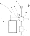
- An inventive principle shown in Figures 1 and 2 Drive device 1 has a motor or electric motor 2, which has a power source 3 with electrical power is supplied.
- the electric motor 2 is on the output side to a suitable transmission device 4 connected by means of which by the electric motor 2 generated drive energy to the in the 1 and 2, not shown, longitudinally movable back and forth Mass is transferable.
- the masses that can be moved back and forth can be motorized movable doors, in particular sliding doors, such as elevator doors or the like.
- the masses can, however also be safety bulkheads or the like, which in Usually closed and opened mechanically.
- the drive device 1 also has a control device 5, which in the embodiment shown in FIG 1 the drive device according to the invention on the input side is connected to a current sensor 6, by means of the operating current of the electric motor 2 is detected. In the Control device 5 thus becomes the current operating current of the electric motor 2 characteristic signal entered.
- control device 5 is connected to one on the input side Temperature sensor 7 connected to the near the electric motor 2 is arranged in its vicinity.
- the temperature behavior of the electric motor 2 within the Control device 5 simulated in software. Approximately shows the temperature behavior of the electric motor 2 low-pass behavior on.
- the temperature sensor 7 for detecting the variable ambient temperature of the electric motor 2 is, as already mentioned, in arranged in close proximity to the electric motor 2.
- variable Ambient temperature of the electric motor 2 also a maximum possible ambient temperature of the electric motor 2 at the simulation of the engine temperature can be used can, with a determination of the actual variable Ambient temperature of the electric motor 2 can be dispensed with can. Because instead of the variable ambient temperature of the Electric motor 2 its maximum possible ambient temperature The basis for the calculation is the simulated one, the Motor temperature value in any case higher than that Value of the engine temperature, which is based on the actual detected by means of the temperature sensor 7 variable ambient temperature results. Accordingly, by the Taking into account a maximum permissible ambient temperature or their basis when simulating the engine temperature an additional safety factor is provided.
- a maximum is within the control device 5 and a minimum thermal time constant of the electric motor 2 registered.
- the maximum thermal to simulate the motor temperature Time constant of the electric motor 2 is used, whereas when the masses moving back and forth during standstills occurring cooling phases of the electric motor 2 the minimum thermal time constant of the electric motor 2 for simulation the engine temperature is used. This ensures that the modeled in the control device 5 In any case, the engine temperature is not below the actual one current motor temperature of the electric motor 2 is.
- variable input current i (t) of the electric motor 2 the constant internal resistance R Wickl. of the electric motor 2, the thermal time constant ⁇ Wickl. of the electric motor 2, the constant thermal winding resistance R th of the electric motor 2 and the variable ambient temperature ⁇ A of the electric motor 2.
- Drive device 1 has the control device 5 a subunit 8 with a counting device 9.
- the Counter 9 has a reversing cycle counter 10, one Leads count value that increases when the movable mass is moved.
- the counter 9 has a downtime summer 11, in the downtime of the moving mass be added up.
- the reversing cycle counter 10 and the standstill summer 11 in a suitable manner with the movable mass, which is not shown in FIG 2, connected.
- the Electric motor receives 2 standstill cycles when the movable Crowd stands still.
- the reversing cycle counter 10 increments when there is a movement the moveable mass and will reverse the direction of movement the movable mass increased by two pulses.
- the downtime totalizer is at a standstill Movable mass, for example, every 10 ms in the controller operating system the control device 5 incremented.
- a decrement the reversing cycle counter 10 is carried out provided the downtime totalizer 11 counts 2 seconds has, whereby the electric motor 2 can cool down.
- the reversing cycle counter 10 has a first limit value, that for a particular motor, for example, at 500 pulses can be reached, the downtime of the movable Measurements in the movement sequence that you can specify on 1 s if it was smaller before.
- the moveable mass is set to 2 s, provided that it is previously was smaller.
- the reversing cycle counter 10 When to the drive device having the control device 5 1 a supply voltage should be applied to to consider any preheating of the electric motor 2, the reversing cycle counter 10 has a default value which is at said electric motor 2 are approximately 400 pulses can get. A network reset until the start of power supply of the electric motor 2 takes about 15 s.
Landscapes
- Control Of Electric Motors In General (AREA)
- Manipulator (AREA)
- Vibration Prevention Devices (AREA)
Applications Claiming Priority (2)
| Application Number | Priority Date | Filing Date | Title |
|---|---|---|---|
| DE19642928 | 1996-10-17 | ||
| DE19642928 | 1996-10-17 |
Publications (3)
| Publication Number | Publication Date |
|---|---|
| EP0837536A2 true EP0837536A2 (fr) | 1998-04-22 |
| EP0837536A3 EP0837536A3 (fr) | 1999-09-01 |
| EP0837536B1 EP0837536B1 (fr) | 2003-09-24 |
Family
ID=7809053
Family Applications (1)
| Application Number | Title | Priority Date | Filing Date |
|---|---|---|---|
| EP97117980A Expired - Lifetime EP0837536B1 (fr) | 1996-10-17 | 1997-10-16 | Dispositif d'entraínement pour masses à mouvement aller et retour, guidé longitudinalement |
Country Status (3)
| Country | Link |
|---|---|
| EP (1) | EP0837536B1 (fr) |
| AT (1) | ATE250815T1 (fr) |
| DE (1) | DE59710777D1 (fr) |
Cited By (2)
| Publication number | Priority date | Publication date | Assignee | Title |
|---|---|---|---|---|
| FR2797530A1 (fr) * | 1999-08-12 | 2001-02-16 | Valeo Equip Electr Moteur | Procede et systeme pour la commande de coupure de demarreur de vehicule automobile |
| EP1298771A3 (fr) * | 2001-09-26 | 2005-12-14 | Moeller GmbH | Dispositif de commande pour un démarreur de moteur |
Family Cites Families (4)
| Publication number | Priority date | Publication date | Assignee | Title |
|---|---|---|---|---|
| DE3136746A1 (de) * | 1980-09-11 | 1983-06-09 | Leopold Kostal GmbH & Co KG, 5880 Lüdenscheid | Schaltungsanordnung zur elektronischen betaetigung und ueberwachung des oeffnungs- bzw. schliesszyklusses von elektrisch betaetigbaren aggregaten |
| JPS58110778A (ja) * | 1981-12-23 | 1983-07-01 | ワイケイケイ株式会社 | 自動開閉扉の制御装置 |
| DE4107207A1 (de) * | 1991-03-04 | 1992-09-10 | Elektro App Werke Veb | Verfahren und einrichtung zum schutz und fuehren von elektromotoren, anderen elektrischen betriebsmitteln oder elektroanlagen nach kriterien der lebensdauer |
| DE4216040A1 (de) * | 1992-05-15 | 1993-11-18 | Bosch Gmbh Robert | Verfahren zur Überwachung eines Elektromotors auf thermische Überlastung |
-
1997
- 1997-10-16 EP EP97117980A patent/EP0837536B1/fr not_active Expired - Lifetime
- 1997-10-16 DE DE59710777T patent/DE59710777D1/de not_active Expired - Lifetime
- 1997-10-16 AT AT97117980T patent/ATE250815T1/de not_active IP Right Cessation
Cited By (2)
| Publication number | Priority date | Publication date | Assignee | Title |
|---|---|---|---|---|
| FR2797530A1 (fr) * | 1999-08-12 | 2001-02-16 | Valeo Equip Electr Moteur | Procede et systeme pour la commande de coupure de demarreur de vehicule automobile |
| EP1298771A3 (fr) * | 2001-09-26 | 2005-12-14 | Moeller GmbH | Dispositif de commande pour un démarreur de moteur |
Also Published As
| Publication number | Publication date |
|---|---|
| ATE250815T1 (de) | 2003-10-15 |
| DE59710777D1 (de) | 2003-10-30 |
| EP0837536B1 (fr) | 2003-09-24 |
| EP0837536A3 (fr) | 1999-09-01 |
Similar Documents
| Publication | Publication Date | Title |
|---|---|---|
| DE3942836C2 (fr) | ||
| DE10247042B3 (de) | Verfahren und Vorrichtung zum Steuern der Aufheizung der Glühkerzen eines Dieselmotors | |
| EP0966782B1 (fr) | Procede de commande et de regulation electriques du deplacement d'unites actionnees electriquement | |
| DE69322175T2 (de) | Vorrichtung zur thermischen Überwachung eines Elektromotors an Bord eines Fahrzeuges, inbesondere für ein Servolenkungssystem | |
| EP0649575B1 (fr) | Commande assuree par moteur electrique | |
| DE3615347C2 (fr) | ||
| EP1528253A1 (fr) | Méthode pour le recuit d'une bougie à incandescence d'un moteur Diesel | |
| DE19730594A1 (de) | Verfahren und Vorrichtung zum Verifizieren des Betriebs von Solenoiden | |
| EP0440757B1 (fr) | Procede et dispositif pour la verification de la capacite de fonctionnement du chauffage d'une sonde de gaz d'echappement et son systeme d'alimentation | |
| DE102013013875A1 (de) | Verfahren zum Steuern eines Roboters | |
| DE4107207A1 (de) | Verfahren und einrichtung zum schutz und fuehren von elektromotoren, anderen elektrischen betriebsmitteln oder elektroanlagen nach kriterien der lebensdauer | |
| DE102008007398A1 (de) | Verfahen und Vorrichtung zum Erkennen des Wechsels von Glühstiftkerzen in einem Brennkraftmotor | |
| EP0816816B1 (fr) | Procédé pour simuler, à l'aide d'un modèle, la température du moyen de refroidissement d'une voiture automobile | |
| DE3246523C2 (fr) | ||
| EP0837536B1 (fr) | Dispositif d'entraínement pour masses à mouvement aller et retour, guidé longitudinalement | |
| WO1992010017A1 (fr) | Procede et dispositif de determination de la sollicitation et/ou de la resistance a la sollicitation de composants ou de groupes de composants a reglage electronique | |
| EP1956171B1 (fr) | Procédé destiné au fonctionnement d'un entraînement de porte et entraînement de porte | |
| EP2258035A2 (fr) | Moteur électrique à système de détection de température et procédé de détection d'une température dans un moteur électrique | |
| DE4036134A1 (de) | Verfahren und einrichtung zur ueberwachung der temperatur von widerstaenden | |
| WO2023006296A1 (fr) | Procédé et appareil pour déterminer une température de point d'accès sans fil dans un composant d'un moteur électrique pour un système d'entraînement électrique | |
| WO2008113308A1 (fr) | Procédé de production d'un signal d'erreur indiquant un état de charge inacceptable pour un moteur électrique et appareil électrique de protection de moteur permettant la mise en oeuvre dudit procédé | |
| DE102012205289A1 (de) | Sicherheitssensor | |
| DE102022134209B3 (de) | Verfahren, Diagnoseeinrichtung und System zum Überwachen eines Betriebs einer Brennkraftmaschine | |
| WO2005040582A2 (fr) | Procede de diagnostic pour actionneur electromecanique | |
| WO2011039006A1 (fr) | Procédé de protection d'un générateur de véhicule automobile contre une surchauffe |
Legal Events
| Date | Code | Title | Description |
|---|---|---|---|
| PUAI | Public reference made under article 153(3) epc to a published international application that has entered the european phase |
Free format text: ORIGINAL CODE: 0009012 |
|
| AK | Designated contracting states |
Kind code of ref document: A2 Designated state(s): AT BE CH DE DK FR GB IT LI NL SE |
|
| AX | Request for extension of the european patent |
Free format text: AL;LT;LV;RO;SI |
|
| PUAL | Search report despatched |
Free format text: ORIGINAL CODE: 0009013 |
|
| AK | Designated contracting states |
Kind code of ref document: A3 Designated state(s): AT BE CH DE DK ES FI FR GB GR IE IT LI LU MC NL PT SE |
|
| AX | Request for extension of the european patent |
Free format text: AL;LT;LV;RO;SI |
|
| 17P | Request for examination filed |
Effective date: 19990917 |
|
| AKX | Designation fees paid |
Free format text: AT BE CH DE DK FR GB IT LI NL SE |
|
| 17Q | First examination report despatched |
Effective date: 20020412 |
|
| GRAH | Despatch of communication of intention to grant a patent |
Free format text: ORIGINAL CODE: EPIDOS IGRA |
|
| GRAS | Grant fee paid |
Free format text: ORIGINAL CODE: EPIDOSNIGR3 |
|
| GRAA | (expected) grant |
Free format text: ORIGINAL CODE: 0009210 |
|
| AK | Designated contracting states |
Kind code of ref document: B1 Designated state(s): AT BE CH DE DK FR GB IT LI NL SE |
|
| PG25 | Lapsed in a contracting state [announced via postgrant information from national office to epo] |
Ref country code: NL Free format text: LAPSE BECAUSE OF FAILURE TO SUBMIT A TRANSLATION OF THE DESCRIPTION OR TO PAY THE FEE WITHIN THE PRESCRIBED TIME-LIMIT Effective date: 20030924 Ref country code: GB Free format text: LAPSE BECAUSE OF FAILURE TO SUBMIT A TRANSLATION OF THE DESCRIPTION OR TO PAY THE FEE WITHIN THE PRESCRIBED TIME-LIMIT Effective date: 20030924 Ref country code: FR Free format text: LAPSE BECAUSE OF FAILURE TO SUBMIT A TRANSLATION OF THE DESCRIPTION OR TO PAY THE FEE WITHIN THE PRESCRIBED TIME-LIMIT Effective date: 20030924 |
|
| REG | Reference to a national code |
Ref country code: GB Ref legal event code: FG4D Free format text: NOT ENGLISH |
|
| REG | Reference to a national code |
Ref country code: CH Ref legal event code: NV Representative=s name: SERVOPATENT GMBH Ref country code: CH Ref legal event code: EP |
|
| REF | Corresponds to: |
Ref document number: 59710777 Country of ref document: DE Date of ref document: 20031030 Kind code of ref document: P |
|
| PG25 | Lapsed in a contracting state [announced via postgrant information from national office to epo] |
Ref country code: BE Free format text: LAPSE BECAUSE OF NON-PAYMENT OF DUE FEES Effective date: 20031031 |
|
| PG25 | Lapsed in a contracting state [announced via postgrant information from national office to epo] |
Ref country code: SE Free format text: LAPSE BECAUSE OF FAILURE TO SUBMIT A TRANSLATION OF THE DESCRIPTION OR TO PAY THE FEE WITHIN THE PRESCRIBED TIME-LIMIT Effective date: 20031224 Ref country code: DK Free format text: LAPSE BECAUSE OF FAILURE TO SUBMIT A TRANSLATION OF THE DESCRIPTION OR TO PAY THE FEE WITHIN THE PRESCRIBED TIME-LIMIT Effective date: 20031224 |
|
| NLV1 | Nl: lapsed or annulled due to failure to fulfill the requirements of art. 29p and 29m of the patents act | ||
| GBV | Gb: ep patent (uk) treated as always having been void in accordance with gb section 77(7)/1977 [no translation filed] |
Effective date: 20030924 |
|
| BERE | Be: lapsed |
Owner name: *SIEMENS A.G. Effective date: 20031031 |
|
| PLBE | No opposition filed within time limit |
Free format text: ORIGINAL CODE: 0009261 |
|
| STAA | Information on the status of an ep patent application or granted ep patent |
Free format text: STATUS: NO OPPOSITION FILED WITHIN TIME LIMIT |
|
| 26N | No opposition filed |
Effective date: 20040625 |
|
| EN | Fr: translation not filed | ||
| PGFP | Annual fee paid to national office [announced via postgrant information from national office to epo] |
Ref country code: CH Payment date: 20050105 Year of fee payment: 8 |
|
| PGFP | Annual fee paid to national office [announced via postgrant information from national office to epo] |
Ref country code: AT Payment date: 20050921 Year of fee payment: 9 |
|
| PG25 | Lapsed in a contracting state [announced via postgrant information from national office to epo] |
Ref country code: IT Free format text: LAPSE BECAUSE OF NON-PAYMENT OF DUE FEES Effective date: 20051016 |
|
| PG25 | Lapsed in a contracting state [announced via postgrant information from national office to epo] |
Ref country code: LI Free format text: LAPSE BECAUSE OF NON-PAYMENT OF DUE FEES Effective date: 20051031 Ref country code: CH Free format text: LAPSE BECAUSE OF NON-PAYMENT OF DUE FEES Effective date: 20051031 |
|
| REG | Reference to a national code |
Ref country code: CH Ref legal event code: PL |
|
| PG25 | Lapsed in a contracting state [announced via postgrant information from national office to epo] |
Ref country code: AT Free format text: LAPSE BECAUSE OF NON-PAYMENT OF DUE FEES Effective date: 20061016 |
|
| PGFP | Annual fee paid to national office [announced via postgrant information from national office to epo] |
Ref country code: DE Payment date: 20151218 Year of fee payment: 19 |
|
| REG | Reference to a national code |
Ref country code: DE Ref legal event code: R119 Ref document number: 59710777 Country of ref document: DE |
|
| PG25 | Lapsed in a contracting state [announced via postgrant information from national office to epo] |
Ref country code: DE Free format text: LAPSE BECAUSE OF NON-PAYMENT OF DUE FEES Effective date: 20170503 |