EP0837601B1 - Signalverarbeitungsverfahren und -schaltung zur Formatumwandlung eines Bildsignals - Google Patents
Signalverarbeitungsverfahren und -schaltung zur Formatumwandlung eines Bildsignals Download PDFInfo
- Publication number
- EP0837601B1 EP0837601B1 EP97117877A EP97117877A EP0837601B1 EP 0837601 B1 EP0837601 B1 EP 0837601B1 EP 97117877 A EP97117877 A EP 97117877A EP 97117877 A EP97117877 A EP 97117877A EP 0837601 B1 EP0837601 B1 EP 0837601B1
- Authority
- EP
- European Patent Office
- Prior art keywords
- signal
- picture
- unit
- processing
- scanning
- Prior art date
- Legal status (The legal status is an assumption and is not a legal conclusion. Google has not performed a legal analysis and makes no representation as to the accuracy of the status listed.)
- Expired - Lifetime
Links
Images











Classifications
-
- G—PHYSICS
- G06—COMPUTING OR CALCULATING; COUNTING
- G06T—IMAGE DATA PROCESSING OR GENERATION, IN GENERAL
- G06T3/00—Geometric image transformations in the plane of the image
- G06T3/40—Scaling of whole images or parts thereof, e.g. expanding or contracting
- G06T3/4007—Scaling of whole images or parts thereof, e.g. expanding or contracting based on interpolation, e.g. bilinear interpolation
-
- H—ELECTRICITY
- H04—ELECTRIC COMMUNICATION TECHNIQUE
- H04N—PICTORIAL COMMUNICATION, e.g. TELEVISION
- H04N7/00—Television systems
- H04N7/01—Conversion of standards, e.g. involving analogue television standards or digital television standards processed at pixel level
- H04N7/0117—Conversion of standards, e.g. involving analogue television standards or digital television standards processed at pixel level involving conversion of the spatial resolution of the incoming video signal
- H04N7/012—Conversion between an interlaced and a progressive signal
-
- H—ELECTRICITY
- H04—ELECTRIC COMMUNICATION TECHNIQUE
- H04N—PICTORIAL COMMUNICATION, e.g. TELEVISION
- H04N7/00—Television systems
- H04N7/01—Conversion of standards, e.g. involving analogue television standards or digital television standards processed at pixel level
- H04N7/0117—Conversion of standards, e.g. involving analogue television standards or digital television standards processed at pixel level involving conversion of the spatial resolution of the incoming video signal
- H04N7/0122—Conversion of standards, e.g. involving analogue television standards or digital television standards processed at pixel level involving conversion of the spatial resolution of the incoming video signal the input and the output signals having different aspect ratios
Definitions
- the present invention relates to signal processing of format conversion of picture signal, particularly to a method and a circuit for signal processing of format conversion of picture signal preferable to converting a plurality of kinds of formats of picture signals into picture signals of predetermined display formats of picture output devices or conversion of flexible compression and flexible expansion of pictures in a horizontal and a vertical direction, or the like.
- a method of dealing with by display As representative methods for realizing the function, there are known a method of dealing with by display and a method of dealing with by signal processing. According to the former method, a picture is displayed by widely setting an operational range of a deflection system of a picture output device and performing a scanning operation in a mode in compliance with a signal format of input pictures, which has been reduced into practice as multi scan system. Although this is an effective method which can be realized at a comparatively low cost when a display unit is a CRT, it is difficult to apply in a planar display such as a liquid crystal display device, a plasma display panel or the like having a constant number of display picture elements.
- format conversion is performed by signal processing and pictures are displayed by converting inputted signals of pictures into signals of display formats of picture output devices, which can be applied to all the picture output devices such as a CRT, a liquid crystal display device, a plasma display panel and the like. Therefore, this is a method that is extremely effective in dealing with diversification of input picture sources or picture output devices predicted in the future. According to the method, various signal processing such as conversion of frame rate, compression and expansion of picture size and the like must be performed for format conversion.
- a television signal of PAL system is converted into a television signal of NTSC system and displayed by a CRT or a liquid crystal display device
- signal processing such as conversion of frame rate, conversion of number of scanning lines, conversion from interlace scanning into progressive scanning, conversion of aspect ratio or the like, compression and expansion, synchronizing and the like are performed independently each other.
- memories having a comparatively large capacity such as a line memory, a frame memory are used in many of these signal processing operations Accordingly, conventionally, a number of memories are needed in a total of signal processing and device cost is increased by using many memories. Further, a variety of input and output interfaces are needed between signal processing and therefore , processing for matching interfaces are often needed, which amounts to an increase in device cost.
- picture quality is slightly deteriorated, which is caused by, for example, quantization error by AD/DA conversion, band restriction by subjecting signals to a filter or the like. Such a picture quality deterioration is accumulated at each signal processing and the picture quality deterioration cannot be disregarded.
- EP-A-0 639 029 discloses a signal processing circuit in with the features included in the first part of claim 1.
- the control of the scaling processing depends only on the input Picture signal and the display format of the picture output device.
- a circuit for signal processing of format conversion of picture signal comprising a scanning convertor for converting an input picture signal into a picture signal of progressive scanning when the input picture signal is of interlace scanning, a selector for selecting either one of the input picture signal and the picture signal of progressive canning outputted from the scanning convertor, a scaling unit for performing signal processing of scaling in horizontal and vertical directions in respect of an output signal from the selector for format conversion and a control unit for selecting parameters of signal processing in accordance with a format of the input picture signal and a display format of a picture output device and controlling at least the scanning convertor, the selector and the scaling unit in accordance with the parameters of the signal processing.
- Such a constitution is realized by commonly using memories in some signal processing, unifying combinations among signal processing by a common digital interface and a common signal system (progressive scanning system) and adopting a centralized control by the control unit.
- Deterioration in picture quality is significantly improved by combining respective signal processing by signals of progressive scanning system. That is, many filtering processing are performed for picture signals in signal processing. In respect of many filters needed in such a picture processing, when progressive scanning system is compared with interlace scanning system, the degree of freedom of design is larger in the progressive scanning system and the filters can be realized with substantially ideal characteristics having high spatial frequencies. Therefore, deterioration in picture quality accompanied by signal processing in format conversion is significantly improved.
- the scaling unit is provided with a horizontal scaling unit performing signal processing of the horizontal scaling and a vertical scaling unit performing signal processing of the vertical scaling.
- a horizontal scaling unit performing signal processing of the horizontal scaling
- a vertical scaling unit performing signal processing of the vertical scaling.
- each of horizontal scaling and vertical scaling is constituted by a combination of a calculation unit for multiplying a plurality of picture elements or picture elements of a plurality of lines by coefficient values, memories and a plurality of numbers of switches by which compression function, expansion function and through function are realized by switching signals by selectively controlling the switches.
- the calculation unit linear interpolation process is performed. A plurality of kinds of processing can be performed by a same circuit through the technical means by which circuit scale necessary for signal processing can significantly be reduced.
- a multi processing unit for performing signal processing of multiplexing a first picture signal and a second picture signal of the same system (for example, NTSC television signals of interlace scanning) to a time-division multiplex signal during 1 scanning line period in which signal processing of format conversion is performed each for the first picture signal in one window and for picture signals outputted from the multi-processing unit in double windows.
- a further reduction in circuit scale necessary for signal processing can be achieved through the technical means.
- the scanning convertor converts the input picture signal into a picture signal of progressive scanning by motion-adaptive process or motion compensative interpolation.
- an output side of the scaling unit is provided with a picture quality improving unit for executing picture quality improving processing such as color space conversion or inverse gamma conversion to the picture signal which has been subjected to signal processing of format conversion.
- component signals of 4:2:0 system comprising luminance signals and two color difference signals (a system where two color difference signals are divided to every other scanning lines and color signals are sampled at a rate of 1/2 of that of luminance signal) or 4:2:2 system (a system where both of two color difference signals are present on one scanning line and color difference signals are sampled at a rate of 1/2 of that of luminance signal).
- Various sources for example, present TV signal, HDTV (High Definition Television) signal, EDTV (Extended Definition Television) signal, personal computer picture, package system picture and the like
- signal processing of two color difference signals can be performed by a memory capacity substantially the same as in luminance signal in the case of 4:2:2 system and a memory capacity of 1/2 of that of luminance signal in the case of 4:2:0 system.
- a signal of progressive scanning is divided into two series of signals and signal processing of horizontal and vertical scaling for format conversion are performed to the two series of the signals.
- the signal processing can be performed at 1/2 operational speed through the technical means.
- the memory capacity necessary for the signal processing is substantially the same as in one series.
- an output side of the scaling unit is provided with a picture quality improving unit for executing picture quality improving processing such as color space conversion, inverse gamma conversion or the like in respect of the picture signal which has been subjected to signal processing of format conversion.
- a picture quality improving unit for executing picture quality improving processing such as color space conversion, inverse gamma conversion or the like in respect of the picture signal which has been subjected to signal processing of format conversion.
- an accuracy of substantially 10 bits/picture element is needed for an output of the picture quality improving processing and therefore, it is necessary to adopt the accuracy of 10 bits/picture element in signal processing at and after the picture quality improvement.
- the process of picture quality improvement is arranged after finishing signal processing of format conversion and therefore, respective signal processing after format conversion can be performed by a normal accuracy of 8 bits/picture element and accordingly, capacities of memories and circuit scale can be reduced.
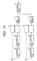
- Fig. 1 is a block diagram showing a format conversion signal processing circuit of picture signals according to the present invention. A detailed explanation will be given later of detailed structures of respective blocks in reference to drawings of numerals designating the blocks.
- An Input picture signal S1 (comprising component luminance and color difference signals of 4:2:2 system or 4:2:0 system or the like) is inputted to an IP convertor 1 and a selector 4.
- the IP convertor 1 constituting a first convertor which is the front stage of the scanning convertor, forms a signal of scanning lines skipped in interlace scanning by motion-adaptive process or motion compensative interpolation in respect of the input picture signal of interlace scanning, and outputs a transmission scanning line signal SM transmitted in interlace scanning and an interpolation scanning line signal SI formed by the above-described interpolation.
- a multiple scan convertor 3 constituting the back stage of the scanning convertor, performs signal processing of 1/2 compression of time axis in the horizontal direction and time-division multiplex in respect of the signals SM and SI respectively and outputs a picture signal SP of progressive scanning.
- the scanning convertor is formed with the IP convertor 1 and the multiple scan convertor 3.
- a selector 4 is constituted by a switch circuit for selecting the signal SP when the input picture signal S1 is the present television (hereinafter, abbreviated as TV) signal of interlace scanning and the input picture signal S1 when the input picture signal S1 is an EDTV signal, a personal computer picture signal or a HDTV signal of progressive scanning, respectively and outputting the signal S1 or the signal SP as a signal S2.
- TV television
- a horizontal scaling unit 5 inputs the signal S2 of progressive scanning outputted from the selector 4, performs signal processing for converting K picture elements into L picture elements in respect of the horizontal direction of the picture (hereinafter, abbreviated as horizontal K-L conversion), and performs horizontal expansion (K ⁇ L) or horizontal compression (K>L) and outputs a converted signal S3.
- a vertical scaling unit 6 performs signal processing for converting K scanning lines into L scanning lines in respect of the vertical direction of the picture (hereinafter, abbreviated as vertical K-L conversion) and performs vertical expansion (K ⁇ L) or vertical compression (K>L).
- system conversion for example, system conversion between PAL system and NTSC system
- signal processing of synchronization and signal processing of PAL 100 Hz when the field frequency of display is 100 Hz are also performed.
- a picture signal S4 with the format of which is converted are outputted.
- a picture quality improving unit 8 inputs the picture signal S4 outputted from the vertical scaling unit 6 that is the final stage of format conversion, performs signal processing of picture quality improvement such as black stretching, white stretching or the like of luminance signals, color space conversion and the like and converts them into RGB signals of three primary colors. Further, signal processing of inverse gamma conversion is performed when a display is a linear property display. Further, a three primary colors picture signal S5 is outputted. A conventionally known one may be used for the picture quality improving unit 8.
- a multiplex unit 9 performs signal processing for multiplexing another three primary colors picture signal S7 for multi pictures displaying (for example, double windows, PIP display, multi windows or the like) in respect of the signal S5. Further, a picture signal S6 in conformity with a format of a display is outputted.
- a microprocessor unit 10 sets signal processing parameters based on a picture format signal SPI (information of kind of input picture signals S1, format of display, mode of picture display and the like) and controls the respective blocks 1, 3, 4, 5, 6, 8 and 9.
- the picture format signal SPI is automatically detected from a frame number, synchronization signal and the like of the input picture signal S1 and from the picture output device at a detector 0.
- the picture format signal SPI may naturally be generated manually.
- a control unit 11 forms synchronization signal, control signal, clock signal and the like necessary for signal processing at the respective blocks and supplies them to the respective blocks. Further, information SD necessary for synchronizing processing in multi windows is outputted. That is, a control unit for generally controlling the respective blocks is constituted by the microprocessor unit 10 and the control unit 11.
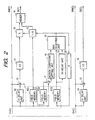
- Fig. 2 is a view of a constitution example of the IP convertor 1 and a memory 2 of Fig. 1. Motion-adaptive interpolation is performed.
- the circuit is substantially the same as a conventionally known circuit.
- a portion of luminance signal Sl(Y) of the input picture signal S1 is outputted as a luminance signal SM(Y) of the transmission scanning line signal SM.
- an interpolation signal suitable for moving picture is formed by adding at an adder 13 a signal delayed by 1H period at an 1H delay unit 12 (notation H designates a period of horizontal scanning line which remains the same in the following explanation) and multiplying a coefficient value 1/2 at a coefficient product unit 14.
- an interpolation signal suitable for stationary picture is formed by a signal delayed by 1 field period at a field memory FD1 in the memory 2. Further, a signal formed by delaying the signal by 1 field period at other field memory FD2, is subtracted at a subtracter 17 by which a differential signal at an interval of 1 frame is detected.
- a motion coefficient setting unit 18 sets a motion information coefficient having a value from 0 to 1 in accordance with an absolute value of the differential signal, that is, a magnitude of motion of picture.
- a MAX selecting unit 19 sets a final motion coefficient K by also using motion information of previous 1 field to avoid motion detection miss.
- the MAX selecting unit 19 constitutes a motion detector.
- Coefficient product units 15 multiply the interpolation signal suitable for moving picture and the interpolation signal suitable for stationary picture by coefficients K and 1-K respectively, and an adder 16 forms a luminance signal SI(Y) of the interpolation scanning line signal SI by adding the both multiplied signals.
- interpolation signals are formed by intrafield interpolation. That is, the signal S1(C) is outputted as a color difference signal SM(C) of the transmission scanning line signal SM, and a color difference signal SI(C) of the interpolation scanning line signal SI is formed by adding a signal delayed by 1 line period in a 1H delay unit 12 to the color difference signal S1(C) at an adder 13 and multiplying the outputted signal from the adder by a coefficient value 1/2 at a coefficient product unit 14.
- the bandwidth of each of two color difference signals u and v comprising the color difference signal S1(C) inputted to the above-described IP convertor 1 and selector 4 is 1/2 of the bandwidth of the luminance signal S1(Y). Therefore, when the input picture signal S1 is of 4:2:2 system, two sets of the circuit having the bandwidth of nearly 1/2 of the bandwidth of the luminance signal Sl(Y) are prepared for processing the two signals u and v.
- the circuit of the above-described IP convertor 1 has such a constitution.
- the circuit for the color difference signal S1(C) is not limited thereto but one set of a circuit can be prepared by using a color signal multiplex unit which multiplexes the two signals u and v into a time-division multiplex color signal.
- the bandwidth of the time-division multiplex color signal becomes double and nearly the same as the bandwidth of the luminance signal S1(Y). Therefore, the circuit for processing the time-division multiplex color signal forms one set of the circuit having nearly the same as the bandwidth of the luminance signal S1(Y).
- the circuit for processing the time-division multiplex color signal can be simplified by reducing the number of circuits.
- the time-division multiplex color signal outputted from the color signal multiplex unit is inputted to the IP convertor 1 and the selector 4.
- Fig. 3A and Fig. 3B are a view of the constitution of a multiple scan convertor 3 of Fig. 1 and a view for explaining the function of a line memory 21 of Fig. 3A, respectively.
- the signals SM(Y) and SM(C) of the transmission scanning line signal SM are stored to line memories 21-1 respectively and the signals SI(Y) and SI(C) of the interpolation scanning line signal SI are stored to line memories 21-2 respectively for 1 line period at an operational speed of interlace scanning by a write operation (hereinafter, abbreviated as WT operation) shown by Fig. 3B.
- WT operation a write operation
- the line memories 21-1 and 21-2 are alternately read in 1 line period (1/2fH) (1/2 time period of interlace scanning) successively at the operational speed of progressive scanning. Further, the signals from the line memories 21-1, 21-2 are multiplexed time-sequentially at a multiplex unit 22 and a luminance signal SP(Y) and a color difference signal SP(C) of the signal SP of progressive scanning are provided as outputs thereof.
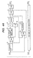
- Fig. 4A and Fig. 4B are a view showing the constitution of the horizontal scaling unit 5 of Fig. 1 and a view showing signal processing parameters for performing selective control of switches in various signal processing, respectively.
- output lines of switches 24(SW1), 28(SW2) and 31(SW4) are connected to terminals "a" and an output line of a switch 30 (SW3) is connected to a terminal "b".
- a luminance signal S2(Y) of the signal S2 of progressive scanning is subjected to band restriction by low pass frequency characteristic at a horizontal LPF 23 to remove horizontal high frequency components constituting an aliasing noise in compression processing.
- linear interpolation process of horizontal K-L conversion (K>L) of picture elements is performed at a calculation unit constituted by a 1 picture element delay unit 25, coefficient product units 26 and an adder 27.
- an input signal to the delay unit 25 and a signal delayed by 1 picture element by the delay element 25 are respectively multiplied by coefficient values ⁇ and 1- ⁇ (1> ⁇ 0) at the coefficient product units 26 and the both are added at the adder 27 thereby providing a signal of L picture elements formed from K picture elements by the horizontal K-L conversion. Further, the coefficient values ⁇ and 1- ⁇ are changed at the respective picture elements with K picture elements as a period.
- the signal of L picture elements is stored to a 1H memory 29 by intermittent WT operation. Further, a signal from the memory 29 is read continuously by RD operation.
- a signal S3(Y) of the signal S3 which has been subjected to horizontal compression by a multiplication factor of L/K is provided as the output from the switch 31.
- the output lines of the switches 24(SW1) and 28(SW2) are connected to terminals "b" and the output lines of the switches 30(SW3) and 31(SW4) are connected to the terminals "a".
- the luminance signal S2(Y) of progressive scanning is continuously stored to the 1H memory 29 by WT operation.
- repetition RD operation is performed at portions of period and a signal of K of picture elements is read in a period of L picture elements.
- Linear interpolation process of K-L conversion (K ⁇ L) of picture elements is performed by the calculation unit constituted by the 1 picture element delay unit 25, the coefficient product units 26 and the adder 27.
- an input signal to the delay unit 25 and a signal delayed by 1 picture element at the delay unit 25 are multiplied by the coefficient values ⁇ and 1- ⁇ at the coefficient product units 26 and the both are added at the adder 27 thereby providing a signal of L picture elements formed from K picture elements by K-L conversion.
- the coefficient values ⁇ and 1- ⁇ are changed at the respective picture elements with L picture elements as a period.
- a signal S3(Y) of the signal S3 which has been subjected to horizontal expansion by a multiplication factor of L/K is provided as the output from the switch 31 (SW4). Further, as mentioned above, in respect of signal processing of horizontal expansion, it is preferable to provide the horizontal scaling unit 5 on the output side of the vertical scaling unit 6.
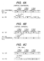
- Fig. 5A and Fig. 5B are a view showing the constitution of the vertical scaling unit 6 of Fig. 1 and a view showing signal processing parameters of selective control of switches in various signal processing, respectively.
- signal processing of compression in a vertical direction hereinafter, abbreviated as vertical compression
- output lines of switches 33(SW1), 37(SW2) and 39(SW4) are connected to terminals "a” and an output line of switch 38(SW3) is connected to a terminal "b", respectively.
- the luminance signal S3(Y) of picture signal of progressive scanning is subjected to band restriction of low pass frequency characteristic at a vertical LPF 32 to remove vertical high frequency components constituting an aliasing noise in compression processing.
- Linear interpolation process of vertical K-L conversion (K>L) of lines is performed by a calculation unit constituted by a 1 line delay element 34, coefficient product units 35 and an adder 36. That is, an input signal to the memory unit 34 and a signal delayed by 1 line at the memory unit 34 are multiplied by coefficient values ⁇ and 1- ⁇ at the coefficient product units 35 and the both are added at the adder 36 thereby providing a signal of L lines formed from K lines by vertical K-L conversion as the output.
- the coefficient values ⁇ and 1- ⁇ are changed at the respective lines with K lines as a period.
- WT operation and RD operation are performed with 1 field period as a period.
- the signal formed by vertical K-L conversion is intermittently written and stored.
- a signal from the memory M-1 is read continuously from time point delayed by (1-L/K ) field period.
- a signal S4(Y) of the signal S4 which has been subjected to vertical compression by a multiplication factor of L/K is provided as the output from the switch 39 (SW4).
- SW4 switch 39
- the output lines of the switches 33(SW1) and 37(SW2) are connected to the terminals "b” and the output lines of the switches 38(SW3) and 39(SW4) are connected to the terminals "a", respectively.
- WT operation and RD operation are performed with 1 field period as one period as shown by Fig. 6B.
- the luminance signal S3(Y) of progressive scanning is stored continuously by WT operation.
- repetition RD operation is performed at portions of period and a signal of L lines is read in a period of K lines.
- linear interpolation process of vertical L-K conversion (L ⁇ K) of lines is performed by the calculation unit constituted by the 1 line delay element 34, the coefficient product units 35 and the adder 36. That is, an input signal to the memory unit 34 and a signal delayed by 1 line at the memory unit 34 are multiplied by the coefficient values ⁇ and 1- ⁇ at the coefficient product units 35 and the both are added at the adder 36 thereby providing a signal of K lines formed from L lines by L-K conversion as the output.
- the coefficient values ⁇ and 1- ⁇ are changed at the respective lines with K lines as a period.
- a signal S4(Y) of the signal S4 which has been subjected to vertical expansion at a multiplication factor K/L is provided as the output from the switch 39(SW).
- a capacity of (1-L/K ) field period is sufficient.
- Signal processing of PAL 100 Hz is for converting a signal having the field frequency of 50 Hz to a signal of interlace scanning of 100 Hz (hereinafter, abbreviated as 625/100/2:1) to remove flickers of PAL television system converted into progressive scanning (hereinafter, abbreviated as 625/50/1:1).
- the processing is realized by connecting the output lines of the switches 37(SW2) and 38(SW3) to the terminals "b" and connecting the output line of the switch 39(SW4) to the terminal "a".
- WT operation and RD operation as shown by Fig. 6C are performed.
- the luminance signal S3(Y) of the PAL signal of progressive scanning is continuously stored by WT operation with 1 field period as a period.
- a signal from the memory M-1 is read in the order of a signal of odd number scanning lines of progressive scanning (designated by ⁇ -0 in Fig. 6C) and a signal of even number scanning lines (designated by ⁇ -E in Fig. 6C) from time point delayed by 0.5 field period.
- a signal S4(Y) of the signal S4 of PAL 100 Hz is provided as the output from the switch 39(SW4).
- the capacity of 0.5 field period is sufficient.
- a NTSC signal converted into progressive scanning (hereinafter, abbreviated as 525/60/1:1) is converted into a signal of 625/100/2:1 system.
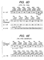
- the processing is realized by connecting the output lines of the switches 33(SW1) and 37(SW2) to the terminals "b", the output line of the switch 38(SW3) to a terminal "c” and the output line of the switch 39(SW4) to the terminal "a", respectively.
- the luminance signals S3(Y) of the NTSC signal of progressive scanning is stored continuously to the memory M-1 by WT operation with NTSC 1 field period as a period.
- RD operation repetition RD operation is performed at portions of period with PAL 1 field period as a period by which a signal of 5 lines is read in a time period of 6 lines.
- a signal outputted from the memory M-2 is read in the order of a signal of odd number scanning lines ( ⁇ -0 in Fig. 6D) and a signal of even number scanning lines ( ⁇ -E in Fig. 6D) from time point delayed by 0.5 field period.
- a signal S4(Y) of the signal S4 of NTSC-PAL 100 Hz is provided as the output from the switch 39(SW4).
- a capacity of 1 field period for NTSC-PAL conversion and 0.5 field period for field multiple scan conversion is sufficient.
- a signal of 625/50/1:1 system is converted into a signal of 525/60/1:1 system in which the output lines of the switches 33(SW1) and 37(SW2) are connected to the terminals "a", the output line of the switch 38(SW3) is connected to the terminal "b” and the output line of the switch 39(SW4) is connected to the terminal "a", respectively.
- the luminance signal S3(Y) of PAL system of progressive scanning is subjected to band restriction by low pass frequency characteristic at the vertical LPF 32.
- vertical compression is performed by linear interpolation process of 6-5 line number conversion by the calculation unit constituted by the 1 line memory unit 34, the coefficient product units 35 and the adder 36.
- an input signal to the memory unit 34 and a signal delayed by 1 line at the memory unit 34 are multiplied by the coefficient values ⁇ and 1- ⁇ at the coefficient product units 35 and both are added at the adder 36 thereby providing a signal of 5 lines formed from 6 lines by 6-5 line number conversion as the output.
- the coefficient values ⁇ and 1- ⁇ are changed for the respective lines with 6 lines as a period.
- a signal formed by 6-5 line number conversion is intermittently written and stored by WT operation with PAL 1 field period as a period. Meanwhile, a signal outputted from the memory M-1 is read in RD operation with NTSC 1 field period as a period.
- a signal S4(Y) of the signal S4 which has been subjected to PAL-NTSC conversion is provided as the output from the switch 39(SW4).
- a capacity of 1 field period is sufficient.
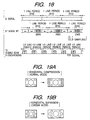
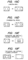
- Fig. 19A through Fig. 19F show pictures of representative examples in format conversion of picture signal.
- a picture is horizontally compressed to display a picture of aspect ratio of 4:3 on a display screen of aspect ratio of 16:9, which is referred to as normal mode.
- a picture is vertically expanded to display a letter box picture in a screen of aspect ratio of 16:9, which is referred to as cinema mode.
- Fig. 19C the left and right corner areas of a picture of aspect ratio of 4:3 are gradually expanded and are displayed in a full screen of aspect ratio of 16:9, which is referred to as smooth wide.
- Fig. 19A a picture is horizontally compressed to display a picture of aspect ratio of 4:3 on a display screen of aspect ratio of 16:9, which is referred to as normal mode.
- Fig. 19B a picture is vertically expanded to display a letter box picture in a screen of aspect ratio of 16:9, which is referred to as cinema mode.
- Fig. 19C the left
- FIG. 19D picture of aspect ratio of 4:3 compressed horizontally is displayed in a full screen of aspect ratio of 16:9, which is referred to as full mode.
- Fig. 19E picture is displayed by compressing in the horizontal and the vertical directions by an arbitrary magnification.
- Fig. 19F picture is displayed by expanding in the horizontal and vertical directions by an arbitrary magnification (referred to as zoom mode).
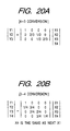
- Fig. 20A through Fig. 20D show equations of representative processing of K-L conversion used in signal processing of format conversion.
- FIG. 20A 4-3 conversion of Fig. 20A is used in normal mode.
- a matrix shown in Fig. 20A indicates a corresponding relationship between 4 points of input series X1, X2, X3 and X4, and 3 points of output series Y1, Y2 and Y3. Therefore, in the above-described calculation unit, the coefficient values ( ⁇ , 1- ⁇ ) are changed to (1, 0), (2/3, 1/3), (1/3, 2/3) thereby forming the output series.
- 3-4 conversion of Fig. 20B is used in cinema mode.
- Fig. 20B indicates a corresponding relationship between 4 points of input series X1, X2, X3 and X4 (incidentally, X4 is used also for X1 of next input series), and 4 points of output series Y1, Y2, Y3 and Y4. Therefore, in the above-described calculation unit, the coefficient values ( ⁇ , 1- ⁇ ) are changed to (0, 1), (1/4, 3/4), (2/4, 2/4), (3/4, 1/4) thereby forming the output series. Further, Fig. 20C shows an example of 6-5 conversion used in PAL-NTSC conversion and Fig. 20D shows an example of 5-6 conversion used in NTSC-PAL conversion.
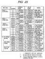
- Fig. 21 shows signal processing at the IP convertor 1, the horizontal and vertical scaling units 5 and 6 with an object of display of a picture signal (526/60/1:1) and aspect ratio of 16:9.
- circle mark in IP conversion represents an operation of carrying out IP conversion.
- the IP conversion is not carried out since it is progressive scanning and through processing, expansion and compression are carried out in accordance with display modes.
- the input signal S1 of PC system (personal computer picture) is of progressive scanning of 60 frames/second and therefore, the IP conversion is not carried out and processing of normal mode display is performed at horizontal and vertical scaling units 5 and 6. That is, in VGA system (640x480), horizontal 4-3 line number conversion is performed, in SVGA system (800x600), horizontal 4-3 line number conversion and vertical 5-4 line number conversion are performed and in XGA system (1024x768), horizontal 4-3 line number conversion and vertical 8-5 line number conversion are performed.
- Fig. 22 shows signal processing at the IP convertor 1, the horizontal and the vertical scaling units 5 and 6 with an object of display of 625/100/2:1 and aspect ratio of 16:9.
- the IP conversion is not carried out since it is progressive scanning and frame rate conversion, 5-6 line number conversion and field multiple scan conversion are performed at the vertical scaling unit 6. Further, processing of through, expansion and compression are performed in accordance with display modes.
- field multiple scan conversion is performed at the vertical scaling unit 6 to the signal converted into progressive scanning at the IP convertor 1. Further, format conversion in correspondence with various display modes is performed.
- the input signal of PC system (personal computer picture) is of progressive scanning of 60 frames/second and therefore, the IP conversion is not carried out and frame rate conversion and field multiple scan conversion are performed at the vertical scaling unit 6. Further, processing for normal mode display is performed. That is, in VGA system (640x480), horizontal 4-3 line number conversion and vertical 5-6 line number conversion are performed, in SVGA system (800x600), horizontal 4-3 line number conversion is performed and in XGA system (1024x768), horizontal 4-3 line number conversion and vertical 4-3 line number conversion are performed.
- Fig. 23 shows signal processing at the IP convertor and the horizontal and vertical scaling units with an object of display of 1125/60/2:1 and aspect ratio of 16:9.
- format conversion in correspondence with various display modes is carried out to the signal converted into progressive scanning at the IP convertor 1. Further, 16-17 line number conversion is also carried out at the vertical scaling unit 6 and the signal inputted to the unit 6 is converted into a signal of interlace scanning.
- the IP conversion is not carried out since it is progressive scanning and processing of through, expansion and compression are performed in accordance with display modes.
- 16-17 line number conversion is also carried out at the vertical scaling unit 6 and the signal inputted to the unit 6 is converted into a signal of interlace scanning.
- the input signal of PC system (personal computer picture) is of progressive scanning of 60 frames/second and accordingly, the IP conversion is not performed and a processing of normal mode display is performed at the horizontal and vertical scaling unit 5 and 6. That is, in VGA system (640x480), horizontal 4-3 line number conversion and vertical 16-17 line number conversion are performed, in SVGA system (800x600), horizontal 4-3 line number conversion and vertical 20-17 line number conversion are performed and in XGA system (1024x768 ) , horizontal 4-3 line number conversion and vertical 32-21 line number conversion are performed.
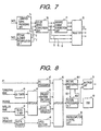
- Fig. 7 shows an example of the constitution of the picture quality improving unit 8 of Fig. 1.
- the luminance signal S4(Y) of picture signal, which has been subjected to format conversion processing is inputted to a luminance processing unit 74 where signal processing of image enhancer, black stretching and white stretching are carried out.
- the color difference signal S4(C) of picture signal which has been subjected to format conversion is inputted to a picture element interpolation unit 75 where signal processing for demodulating the color signal S4(C) into color difference signals U and V having the structure of sample point the same as in the luminance signal.
- a color space convertor 76 carries out conversion processing from a luminance and color difference system to a three primary colors RGB system.
- an inverse gamma processing unit 77 carries out signal processing of inverse gamma correction for a display having a linear characteristic.
- a selector 78 selects a signal from the color space convertor in a display having a gamma characteristic as in CRT or the like and selects a signal from the inverse gamma processing unit 77 in a display having a linear characteristic as in a liquid crystal display device or a plasma display panel and outputs them as three primary color image signals S5.
- a method and a circuit for signal processing of format conversion of picture signal having inconsiderable deterioration of picture quality accompanied by signal processing and an extremely small memory capacity for use at low cost can be realized.
- Fig. 8 shows an embodiment of a television receiver using a circuit for signal processing of format conversion of picture signal according to the embodiment. Respective blocks shown in Fig. 8 and a picture output device (not illustrated) are integrated into a television receiver. A conventionally known one may be used for the picture output device.
- Terrestrial broadcast wave is received by a UV tuner 40 and demodulated into a picture signal of base band. Satellite broadcast wave is received by a BS/CS tuner 41 and is demodulated into a picture signal of base band. Further, a switcher 42 selects and outputs one from the demodulated picture signals and picture signals of the package (CD-ROM, video tape) systems.
- a present system decoder 43 performs signal processing of YC (luminance and color) separation and color demodulation in respect of a picture signal of NTSC system or PAL system and demodulates the signal into luminance and color difference signals of component 4:2:2 system (or 4:2:0 system).
- An ED/HD decoder 44 performs signal processing of demodulation in respect of a picture signal of EDTV system or HDTV system and demodulates the signal into luminance and color difference signals of progressive scanning in EDTV system or component 4:2:2 system (or 4:2:0 system) of interlace scanning in HDTV system.
- Digital broadcast wave is received by a digital receiver 45 and is demodulated into a bit stream signal by performing signal processing of descramble, error correction and the like.
- the bit stream signal is demodulated into luminance and color difference signals of component 4:2:2 system (or 4:2:0 system) by performing demodulation processing at an MPEG decoder 46.
- a PC picture signal (three primary colors RGB signal) is inputted to a PC processing unit 47 and converted into luminance and color difference signals of component 4:2:2 system (or 4:2:0 system) by performing signal processing of color space conversion to luminance and color difference system.
- a switcher 48 selects and outputs these signals.
- a picture processing unit 49-1 performs signal processing of converting a picture signal into a format of a display in the format conversion signal processing circuit of picture signals shown by Fig. 1.
- a signal from the picture processing unit 49-1 is outputted and in multi windows mode, signals formed by multiplexing the signal from the picture processing unit 49-1 as a main picture with a signal as a sub picture from a picture processing unit 49-2 where synchronizing with the main picture is carried out by the information SD.
- a multiplex unit 51 performs processing of multiplexing on screen pictures formed by OSD (On Screen Display) 50 (means for forming small other picture in one picture in case of forming pictures of personal computer or the like) to the signal, supplies the output signal to a picture output device (not illustrated in the drawings). In the picture output device, the picture whose format is converted to a predetermined display format is displayed.
- OSD On Screen Display
- a microcomputer control unit 52 sets the input signals or display modes, controls signal processing at respective blocks and the like. Incidentally, connections between the microcomputer control unit 52 and the respective blocks are omitted.
- a television receiver for receiving and displaying picture signals from various input sources can be realized at low cost by reducing necessary memories.
- the picture processing unit 49 it may also be constituted in a second through a fourth embodiment mentioned below. Further, in the following explanation of embodiments, the same numerals are attached to constitutions or function portions substantially the same as those in the first embodiment and an explanation thereof will be omitted.
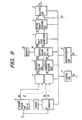
- Fig. 9 shows a format conversion signal processing circuit of picture signal. Signal processing at horizontal and vertical scaling units is performed under a state of two series of signals of interlace scanning and thereafter, the signals are converted into a signal of progressive scanning. That is, an input picture signal is divided into two series and signal processing of horizontal and vertical scaling units is performed to each of the divided signals.
- the input picture signal S1 (comprising component luminance and color difference signals of 4:2:2 system or 4:2:0 system) is inputted to the IP convertor 1 and a 2 channel division unit 53.
- the IP convertor 1 operates to the input picture signal S1 of interlace scanning and is provided with the constitution and operation the same as those shown by Fig. 2.
- the 2 channel division unit 53 forms two series of signals SM' and SI' of interlace scanning from the input picture signal S1 of progressive scanning.
- the 2 channel division unit constitutes a second convertor.
- the selector 4 selects respectively the signals SM and SI when the input picture signal S1 is the present TV signal of interlace scanning and the signals SM' and SI' when the signal S1 is the EDTV signal, the personal computer picture signal or the HDTV signal of progressive scanning and outputs the selected signals as signals S2M and S2I.
- the horizontal scaling units 5 perform horizontal expansion (K ⁇ L) or horizontal compression (K>L) by signal processing of horizontal K-L conversion for each of the signals S2M and S2I and output signals S3M and S3I expanded or compressed in the horizontal direction.
- a vertical scaling unit 54 performs vertical expansion (K ⁇ L) or vertical compression (K>L) by signal processing of vertical K-L conversion to the signals S3M and S3I. Further, depending on the kind of the input signal S1, similar to Embodiment 1, signal processing of system conversion (for example, PAL-NTSC conversion) or synchronization is performed and depending on a display, signal processing of PAL 100 Hz is performed along therewith. Further, signals S4M and S4I the format of each of which is converted are outputted.
- the multiple scan convertor 3 performs signal processing of 1/2 compression of time axis and time-division multiplex in the horizontal direction for each of the signals S4M and S4I and outputs a picture signal S4 of progressive scanning.
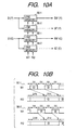
- Fig. 10A and Fig. 10B are a block diagram of the 2 channel division unit 53 of Fig. 9 and a view for explaining the operation, respectively.
- the luminance signal Sl(Y) and the color difference signal S1(C) of the input picture signal S1 of progressive scanning are respectively inputted to line memories 56-1 and 56-2.
- the line memory 56-1 stores signals (scanning lines 1 ⁇ , 3 ⁇ , ⁇ in figure) of scanning lines corresponding to first interlace scanning in WT operation for 1 line period of fH. Meanwhile, in RD operation, signals are read for a time period of 2fH twice as much as that in WT operation by which signals SM'(Y) and SM'(C) of interlace scanning are provided.
- the line memory 56-2 stores signal (scanning lines 2 ⁇ , 4 ⁇ , ⁇ in figure) of scanning lines corresponding to second interlace scanning in WT operation for 1 line period of fH. Meanwhile, in RD operation, signals are read for a time period of 2fH twice as much as that in WT operation by which signals SI'(Y) and SI'(C) of interlace scanning are provided.
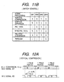
- Fig. 11A and Fig. 11B are a block diagram of the vertical scaling unit 54 of Fig. 9 and a view showing the operation of selective control of switches in the vertical scaling unit 54.
- the signals S3M(Y) and S3I(Y) are multiplied by coefficient values ⁇ and 1- ⁇ at the coefficient product units 60 and both are added at the adder 61.
- a signal formed by delaying the signal S3M(Y) by 1 line at the 1 line delay element 59 and the signal S3I(Y) are multiplied by coefficient values y and 1-y at the coefficient product units 60 and both are added at the adder 61.
- two series of signals comprising signals of L lines formed from K lines by vertical K-L conversion are provided.
- the coefficient values ⁇ , 1- ⁇ , ⁇ and 1- ⁇ are changed at the respective lines.
- the coefficient values ( ⁇ , 1- ⁇ ) are changed for each line such as (1,0), (1/3, 2/3), (2/3, 1/3), (1, 0), ⁇
- the coefficient values ( ⁇ , 1- ⁇ ) are changed for each line such as (2/3, 1/3), (1, 0), (1/3, 2/3), (2/3, 1/3), w ⁇ .
- WT operation and RD operation are performed with 1 field period as a period.
- the output lines of the switches 58(SW1) and 63(SW2) are connected to the terminals "b" and the output lines of the switches 64(SW3) and 65(SW4) are connected to the terminals "a".
- WT operation and RD operation are performed with 1 field period as a period.
- the luminance signals S3M(Y) and S3I(Y) of two series of picture signals are continuously stored by WT operation.
- RD operation repetition RD operation is performed at portions of period and two series of signals of L lines are read in a period of K lines.
- Linear interpolation process of L-K conversion (L ⁇ K) of lines is performed by the calculation unit constituted by the 1 line delay element 59, the coefficient product units 60 and the adders 61. That is, in one signal way, the signals of S3M(Y) and S3I(Y) are multiplied by the coefficient values ⁇ and 1- ⁇ at the coefficient product units 60 and both are added at the adder 61.
- a signal produced by delaying the signal S3M(Y) by 1 line at the 1 line delay element 59 and the signals of S3I(Y) are multiplied by coefficient values ⁇ and 1- ⁇ at the coefficient product units 60 and both are added at the adder 61.
- Two series of signals comprising signals of K lines formed from L lines by L-K conversion are provided as outputs.
- the coefficients values ⁇ , 1- ⁇ , ⁇ and 1- ⁇ are changed at the respective lines.
- the coefficient values ( ⁇ , 1- ⁇ ) are changed for the respective lines such as (1, 0), (2/4, 2/4), (1, 0), ⁇ and the coefficient values ( ⁇ , 1- ⁇ ) are changed for the respective lines such as (1/4, 3/4), (3/4, 1/4), (1/4, 3/4) ⁇ .
- two series of signals S4M(Y) and S4I(Y) which have been vertically expanded by a multiplication factor K/L are provided as outputs of the switch 65(SW4).
- a signal of (1-L/K ) field period is sufficient.
- a signal of PAL system (625/50/1:1) converted into progressive scanning is converted into a signal of PAL 100 Hz system (625/100/2:1) of interlace scanning of 100 fields/second, which is realized by respectively connecting the output lines of SW2 and SW3 to the terminals "b" and the output line of SW4 to the terminal "a".
- WT operation and RD operation shown by Fig. 12C are performed.
- the luminance signals S3M(Y) and S3I(Y) of two series of PAL signals are stored continuously in WT operation with 1 field period as a period.
- signals are read in the order of a signal ( ⁇ -0 in figure) and a signal ( ⁇ -E in figure) from time point delayed by 0.5 field period. Further, two series of signals SM4(Y) and S4I(Y) of PAL 100 Hz are provided as outputs from the switch 65(SW4). As memory capacity necessary for signal processing of PAL 100 Hz described above, a capacity of 1 field period is sufficient.
- a signal of NTSC system (525/60/1:1) converted into progressive scanning are converted into a signal of 625/100/2:1 system in which the output lines of the switches 58(SW1) and 63(SW2) are connected to the terminals "b", the output line of the switch 64(SW3) is connected to a terminal "c” and the output line of the switch 65(SW4) is connected to the terminal "a", respectively.
- the luminance signals S3M(Y) and S3I(Y) of two series of NTSC system are continuously stored to the memory M1 by WT operation with NTSC 1 field period as a period. Meanwhile, in RD operation, repetition RD operation is performed at portions of period and two series of signals of 5 lines are read in a period of 6 lines.
- Two series of signals comprising signals of 6 lines formed from 5 lines by 5-6 line number conversion are provided as the outputs of addition.
- the coefficient values ⁇ , 1- ⁇ , ⁇ and 1- ⁇ are respectively changed at the respective lines.
- Signals are stored continuously in WT operation to a memory M2 of the memory 55 with PAL 1 field as a period.
- signals are read in the order of a signal ( ⁇ -0 in figure) and a signal ( ⁇ -E in figure) from time point delayed by 0.5 field period.
- two series of signals S4M(Y) and S4I(Y) of NTSC-PAL 100 Hz are provided as outputs from the switch 65(SW4).
- a capacity of 1 field period for NTSC-PAL conversion and 1 field period for field multiplex scan conversion is sufficient.
- a signal of 625/50/1:1 system is converted into a signal of 525/60/1:1 system in which the output lines of the switches 58(SW1) and 63(SW2) are connected to the terminals "a", the output line of the switch 64(SW3) is connected to the terminal "b” and the output line of the switch 65(SW4) is connected to the terminal "a", respectively.
- the luminance signals S3M(Y) and S3I(Y) of two series of PAL system are subjected to band restriction by low pass frequency characteristic at the vertical LPF 57.
- Vertical compression is performed by linear interpolation process of 6-5 line number conversion of lines at the calculation unit constituted by the 1 line delay element 59, the coefficient product units 60 and the adders 61.
- the signal of S3M(Y) and S3I(Y) are multiplied by the coefficient values ⁇ and 1- ⁇ at the coefficient product units 60 and both are added at the adder 61.
- a signal formed by delaying the signal S3M(Y) by 1 line at the 1 line delay element 59 and the signal S3I(Y) are multiplied by the coefficient values ⁇ and 1- ⁇ at the coefficient product units 60 and both are added at the adder 61.
- Two series of signals comprising signals of 5 lines formed from 6 lines by 6-5 line number conversion are provided as the outputs.
- the coefficient values ⁇ , 1- ⁇ , ⁇ and 1- ⁇ are changed at the respective lines.
- Fig. 12E at the memory M1, two series of signals formed by 6-5 line number conversion are intermittently written and stored by WT operation with PAL 1 field period as a period. Meanwhile, in RD operation, two series of signals are read with NTSC 1 field period as a period. Further, signals S4M(Y) and S4I(Y) which have been subjected to PAL-NTSC conversion are provided as outputs from the switch 65.
- a capacity of PAL 1 field period is sufficient.
- the output line of the switch 65 is connected to the terminal "b". Further, two series of signals S4M(Y) and S4I(Y) which have not been subjected to processing of compression or expansion are provided as outputs from the switch 65.
- color signals S3M(C) and S3I(C) of two series of picture signals signal processing having the constitution the same as that in luminance signals is performed and two series of signals S4M(C) and S4I(C) of vertical compression, vertical expansion, PAL 100 Hz, NTSC-PAL 100 Hz, PAL-NTSC conversion or through processing are provided.
- the vertical scaling unit 54 various kinds of signal processing necessary for format conversion can be carried out with an extremely small memory capacity.
- a method and a circuit for signal processing of format conversion of picture signal having inconsiderable deterioration of picture quality accompanied by signal processing and an extremely small memory capacity for use can be realized at low cost.
- Fig. 13 shows an embodiment of a format conversion circuit of picture signal according to the present invention.
- a multi processing unit 66 for synthesizing two series of input picture signals and a selector 67 are added to the constitution shown by Fig. 1, which is preferable in the case where both of functions of double windows and PIP display are realized.
- Fig. 13 portions having the constitution and function substantially the same as those in Fig. 1 are attached with notations the same as those in Fig. 1 and a detailed explanation thereof will be omitted.
- a first input picture signal S1 (comprising component luminance and color difference signals of 4:2:2 system or 4:2:0 system) is inputted to the multi processing unit 66 and the selector 67. Further, a second input picture signal S1' (comprising component luminance and color difference signals of 4:2:2 system or 4:2:0 system) is inputted to the multi processing unit 66.
- signal processing of multiplexing the first and the second picture signals into a time-division multiplex signal is carried out by which a signal for double windows or PIP display is formed.
- the selector 67 outputs the first picture signal S1 in one window mode and a signal from the multi processing unit 66 in double windows or PIP display mode.
- Fig. 14 is a block diagram showing the constitution of the multi processing unit 66
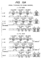
- Fig. 15A is a view for explaining an outline of the operation of the multi processing unit in double windows according to the embodiment
- Fig. 15B is a view for explaining an outline of the operation of the multi processing unit in PIP display, respectively.
- selectors 70 select signals of S1 and S1' in double windows of cut mode and signals from the sub sampling units 69 in the other cases.
- Line memories 71 perform WT operation and RD operation shown by Figs. 15A and 15B. Output signals from the line memories 71 are subjected to time division multiplex at a multiplex unit 72 by which a signal for double windows or PIP display is formed. A detailed description will be given of the operation of the line memories 71 in reference to Figs. 15A and 15B as follows. Both Figs. 15A and 15B show a case where 1 line is constituted by 910 picture elements and a number of effective picture elements among them is 768.
- Fig. 15A shows the operation of the memories 71 in double windows.
- each of picture signals S1 and S1' is displayed at 3/5 of screen (hatched region in figure).
- signals of 454 picture elements shown by dots are stored with 1 line period as a period.
- phases of horizontal synchronization are shifted normally between the signals S1 and S1'.
- RD operation is performed by a synchronizing system of the signal S1.
- a signal (O-L in figure) of the signal S1 is read in a period of 454 picture elements from the front of 1 line, and a signal ( ⁇ -R in figure) of the signal S1' is read in a period of successive 454 picture elements.
- Fig. 15B shows operation of the memories 71 in PIP display.
- a main picture is constituted by picture of the signal S1
- a sub picture is constituted by picture of cinema mode formed by compressing picture of the signal S1' by 1/3. Therefore, according to WT operation, all of 768 effective picture elements of the signal S1 are stored with 1 line as a period. Further, in respect of the signal S1', a signal of 128 picture elements which has been subjected to 6:1 sub sampling is stored.
- RD operation is performed by the synchronizing system of the signal S1, in which the 768 picture elements signal of the signal S1 is read from the front of 1 line and the 128 picture elements signal of the signal S1' is read successively. Output signals which have been subjected to horizontal synchronization are provided by the RD operation. Further, phase shift of vertical synchronization is corrected by signal processing of vertical synchronization at a vertical scaling unit 6, mentioned later.
- Fig. 16A shows content of signal processing of horizontal and vertical scaling units 5 and 6 in double windows and PIP display
- Fig. 16B shows an outline view of vertical synchronization
- Fig. 16C shows an outline of the operation of a memory in vertical synchronization, respectively.
- the horizontal scaling unit 5 performs processing of 4-3 line number compression conversion and the vertical scaling unit 6 performs processing of vertical synchronization. Further, in full mode, the vertical scaling unit 6 performs processing of 3-2 line number compression conversion and vertical synchronization. Meanwhile, in PIP display, the horizontal scaling unit 5 performs 4-3 line number compression conversion in respect of a main picture, processing of 1-2 line number expansion conversion in respect of a sub picture and the vertical scaling unit 6 performs processing of 9-4 line number compression conversion and vertical synchronization in respect of the sub picture. Further, in respect of one window display, processing similar to that in the first embodiment mentioned above is carried out.
- a signal (earlier half of each line) of the signal S1 is stored to the memory 71 by WT operation. Further, RD operation is performed by the synchronization system of the signal S1 and a signal which has been subjected to vertical synchronization is read. Incidentally, as memory capacity necessary for the signal processing, a capacity of 1 field period is sufficient at maximum.
- a signal (earlier half of each line) of the signal S1 formed by 3-2 line number conversion and a signal (later half of each line) of the signal S1' are intermittently written and stored.
- both of reading of the signal (earlier half of each line) of the signal S1 and reading of the signal (later half of each line) of the signal S1' are performed by the synchronizing system of the signal S1.
- a signal having vertical synchronization is provided.
- a method and a circuit for signal processing of format conversion of picture signal having both functions of double windows and PIP display can be realized with inconsiderable deterioration of picture quality accompanied by signal processing and with an extremely small memory capacity for use at low cost.
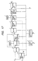
- Fig. 17 shows a fourth embodiment of a format conversion circuit of picture signal according to the present invention.
- the embodiment is provided with the constitution similar to that in Embodiment 3.
- the sampling is constituted by 3:1 sub sampling by which a number of picture elements is increased.
- the embodiment is preferable in the case where the functions of performing double windows and PIP display are also realized similar to Embodiment 3.
- a multi processing unit 73 is a processing unit for carrying out such a sub sampling.
- the first input picture signal S1 (comprising component luminance and color difference signals of 4:2:2 system or 4:2:0 system) is inputted to the multi processing unit 73 and the selector 67.
- a second input picture signal S1' (comprising component luminance and color difference signals of 4:2:2 system or 4:2:0 system) is inputted to the multi processing unit 73.
- the multi processing unit 73 performs signal processing of multiplexing the first and the second picture signals S1 and S1' into a time division multiplex signal which forms a signal for double windows and a signal of the sub picture for PIP display.
- the selector 67 outputs the first picture signal S1 in one window mode and a signal outputted from the multi processing unit 73 in double windows.
- Fig. 18 is a view for explaining formation of the sub picture signal for PIP display at the multi processing unit 73.
- a main picture is constituted by the picture of the signal S1 and the sub picture is constituted by a picture of cinema mode formed by compressing the picture of the signal S1' by 1/3.
- a signal of 256 picture elements provided by performing 3:1 sub sampling to the signal S1' is stored to the memory 71 by WT operation with 1 line period as a period in a synchronizing system of the signal S1'.
- RD operation a signal is read at a speed twice as much as that of WT operation by the synchronizing system of the signal S1.
- a sub picture signal PIP in a mode of progressive scanning having horizontal synchronization of the signal S1 is formed.
- the signal PIP is subjected to processing of 9-4 line number compression conversion and vertical synchronization at the vertical scaling unit 6 by which the sub picture of cinema mode is constituted.
- the constitution and signal processing of the embodiment are similar to those in Embodiment 3 and an explanation thereof will be omitted.
- Embodiment 4 a method and a circuit for signal processing of format conversion of picture signal having both functions of double windows and PIP display, can be realized with inconsiderable deterioration of picture quality accompanied by signal processing and an extremely small memory capacity for use at low cost.
- a method and a circuit for signal processing of format conversion of picture signal for converting a plurality of formats of picture signals into picture signals of predetermined display formats of picture output devices or performing scaling processing of flexible expansion and compression in the horizontal and the vertical directions of picture can be realized with inconsiderable deterioration of picture quality accompanied by signal processing and an extremely small memory capacity for use at low cost. Therefore, a significant effect is achieved in promoting function of various information device terminals in correspondence with multimedia and reduction in cost.
Landscapes
- Engineering & Computer Science (AREA)
- Computer Graphics (AREA)
- Multimedia (AREA)
- Signal Processing (AREA)
- Physics & Mathematics (AREA)
- General Physics & Mathematics (AREA)
- Theoretical Computer Science (AREA)
- Television Systems (AREA)
- Details Of Television Scanning (AREA)
- Controls And Circuits For Display Device (AREA)
- Image Processing (AREA)
- Color Television Systems (AREA)
Claims (21)
- Signalverarbeitungsschaltung zum Umwandeln des Formats eines Bildeingangssignals (S1) in das eines Bildausgabegeräts mit
einem Abtastwandler (1, 3) zur Durchführung einer ersten lokalen Signalverarbeitung zum Umwandeln des Bildeingangssignals (S1) in ein fortschreitendes Bildabtastsignal, wenn es sich bei dem Bildeingangssignal (S) um ein Zeilensprungsignal handelt,
einer ersten Wählstufe (4) zum Auswählen des Bildeingangssignals (S1) oder des von dem Abtastwandler (1,3) ausgegebenen Bildsignals (SP),
einer Skaliereinheit (5, 6) mit einer Horizontal-Skaliereinheit (5) zur Durchführung einer zweiten lokalen Signalverarbeitung zum Komprimieren und Expandieren des von der ersten Wählstufe (4) ausgewählten Signals (S2) in Horizontalrichtung und einer Vertikal-Skaliereinheit (6) zur Durchführung einer dritten lokalen Signalverarbeitung zum Komprimieren und Expandieren in einer dazu senkrechten Richtung und
einer Steuereinheit (11) zum Auswählen von Signalverarbeitungsparametern, zu denen Informationen über Komprimier- und Expandierverhältnisse in Horizontal- oder Vertikalrichtung sowie die Notwendigkeit der progressiven Abtastumwandlung entsprechend dem Format des Bildeingangssignals (S1) und dem des Bildausgabegeräts gehören, sowie zum Steuern des Abtastwandlers (1,4), der ersten Wählstufe (4) und der Skaliereinheit (5, 6) in Übereinstimmung mit den gewählten Signalverarbeitungsparametern,
wobei die Steuereinheit (11) die Signalverarbeitungsparameter entsprechend einer Kombination aus dem Format des Bildeingangssignals (S1) und einem angegebenen Bildanzeigemodus auswählt,
dadurch gekennzeichnet, daß die Schaltung ferner aufweist:wobei die Steuereinheit (11) bewirkt, daß der Abtastwandler (3), die erste Wählstufe (4) und die Skaliereinheit (5, 6) die Signalverarbeitung im Falle einer Einfenster-Darstellung an dem ersten Bildsignal (S1) und im Falle eines Doppelfensters an dem von der Mehrfachverarbeitungseinheit (66) ausgegebenen Zeitmultiplexsignal durchführen.eine Mehrfachverarbeitungseinheit (66) zur Eingabe eines ersten und eines zweiten Bildsignals (S1, S1') und zur Durchführung einer vierten lokalen Signalverarbeitung zum Multiplexen des ersten und des zweiten Bildsignals (S1, S1'), um während einer Zeilenabtastperiode ein Zeitmultiplexsignal zu erzeugen, undeine zweite Wählstufe (67) zur Bildung des Bildeingangssignals (S1) durch Auswählen des ersten Bildsignals (S1) oder des von der Mehrfachverarbeitungseinheit (66) ausgegebenen Zeitmultiplexsignals, - Schaltung nach Anspruch 1, wobei der Abtastwandler aufweist:einen ersten Wandler (1) zum Umwandeln des Bildeingangssignals (S1) in ein im Zeilensprung übertragenes Transmissions-Zeilenabtastsignal (SM) und ein Interpolations-Zeilenabtastsignal (SI), das dadurch entsteht, daß die bei der Zeilensprungabtastung übersprungenen Abtastzeilen interpoliert werden, wenn das Bildeingangssignal (S1) ein Zeilensprungsignal ist, undeinen Mehrfach-Abtastwandler (3) zum Multiplexen des Transmissions-Zeilenabtastsignals (SM) und des Interpolations-Zeilenabtastsignals (SI) unter Erzeugung eines progressiven Zeilenabtastsignals (SP) durch eine fünfte lokale Signalverarbeitung durch Zeitmultiplexen mit Kompression der Zeitachse um 1/2.
- Schaltung nach Anspruch 2, wobei der erste Wandler (1) aufweist:einen Bewegungsdetektor (19) zum Erfassen eines Bildbewegungskoeffizienten (K) des Bildeingangssignals (S1),eine Schaltung (12, 13, 14) zur Erzeugung von ersten und zweiten Interpolationssignalen (SM(Y), SI(Y), SM(C), SI(C)) durch Ausführen einer Intrafeld- bzw. einer Interfeld-Berechnung an dem Bildeingangssignal (S1) undeine Schaltung (16) zur Erzeugung des Interpolations-Zeilenabtastsignals (SI) durch Ändern des Mischverhältnisses der ersten und zweiten Interpolationssignale mittels des Bewegungskoeffizienten (K).
- Schaltung nach Anspruch 1, wobei die Horizontal-Skaliereinheit (5) aufweist:wobei durch selektive Steuerung der Schalter (24, 28, 30, 31) eine Signalverarbeitung durch Komprimieren in Horizontalrichtung, Expandieren in Horizontalrichtung oder Weitergabe selektiv durchgeführt wird.ein Tiefpassfilter (23) zum Entfernen von Aliasing-Rauschen aus dem Eingangssignal für die Horizontal-Skaliereinheit (5),einen Einzeilen-Horizontal-Abtastspeicher (29),einen ersten Schalter (24) zum Auswählen des Ausgangssignals des Einzeilen-Horizontal-Abtastspeichers (29) oder des Ausgangssignals des Tiefpassfilters (23),eine Rechenstufe (25, 26, 27) zum Verzögern des Ausgangssignals des ersten Schalters (24) um eine Bildelementperiode, Erzeugen eines ersten Signals durch Multiplikation des verzögerten Signals mit einem Koeffizient β (1 > β ≥ 0), Erzeugen eines zweiten Signals durch Multiplikation des Ausgangssignals des ersten Schalters (24) mit einem Koeffizient 1-β, und Addieren des ersten und des zweiten Signals,einen zweiten Schalter (28) zum Auswählen entweder des Eingangssignals der Horizontal-Skaliereinheit (5) oder des Ausgangssignals der Rechenstufe (25, 26, 27) und Eingeben des ausgewählten Signals in den Einzeilen-Horizontal-Abtastspeicher (29),einen dritten Schalter (30) zum Auswählen des Ausgangssignals des Einzeilen-Horizontal-Abtastspeichers (29) oder des Ausgangssignals der Rechenstufe (25, 26, 27), undeinen vierten Schalter (31) zum Auswählen des Ausgangssignals des dritten Schalters (30) oder des Eingangssignals der Horizontal-Skaliereinheit (5),
- Schaltung nach Anspruch 1, wobei die Vertikal-Skaliereinheit (6) aufweist:wobei durch selektive Steuerung der Schalter (33, 37, 38, 39) eine Signalverarbeitung durch Komprimieren in Vertikalrichtung, Expandieren in Vertikalrichtung, Weitergabe, Mehrfeldabtastung oder PAL-NTSC-Umwandlung selektiv durchgeführt wird.ein erstes Tiefpassfilter (32) zum Entfernen von Aliasing-Rauschen aus dem Eingangssignal der Vertikal-Skaliereinheit (6),einen ersten Feldspeicher (M-1),einen ersten Schalter (33) zum Auswählen des Ausgangssignals des ersten Feldspeichers (M-1) oder des Ausgangssignals des Tiefpassfilters (32),eine Rechenstufe (34, 35, 36) zur Erzeugung eines ersten Signals durch Verzögern des Ausgangssignals des ersten Schalters (33) um eine Zeilenperiode und Multiplikation des verzögerten Ausgangssignals mit einem Koeffizient β (1 > β ≥ 0), Erzeugen eines zweiten Signals durch Multiplikation des Ausgangssignals des ersten Schalters (33) mit einem Koeffizient 1-β und Addieren des ersten und des zweiten Signals,einen zweiten Schalter (33) zum Auswählen des Eingangssignals der Vertikal-Skaliereinheit (6) oder des Ausgangssignals der Rechenstufe (33, 35, 36) und Eingeben des ausgewählten Signals in den ersten Feldspeicher (M-1),einen zweiten Feldspeicher (M-2) zum Verzögern des Ausgangssignals der Rechenstufe (34, 3 5, 36),einen dritten Schalter (38) zum Auswählen der von der Rechenstufe (34, 35, 36) ausgegebenen Signale, des Ausgangssignals des ersten Feldspeichers (M-1) oder des Ausgangssignals des zweiten Feldspeichers (M-2), undeinen vierten Schalter (39) zum Auswählen des Ausgangssignals des dritten Schalters (38) oder des Eingangssignals der Vertikal-Skaliereinheit (6),
- Schaltung nach Anspruch 1, wobei die Horizontal-Skaliereinheit (5) und die Vertikal-Skaliereinheit (6) Schaltungen zur Durchführung der zweiten lokalen Signalverarbeitung zum Komprimieren in Horizontalrichtung und Expandieren in Horizontalrichtung sowie der dritten lokalen Signalverarbeitung zum Komprimieren in Vertikalrichtung bzw. Expandieren in Vertikalrichtung durch lineare Interpolation aufweisen.
- Schaltung nach Anspruch 1, wobei an einer Ausgangsklemme der Skaliereinheit (5, 6) eine von der Steuereinheit (11) gesteuerte Bildverbesserungsstufe (8) angeschlossen ist, die eine Signalverarbeitung durch Farbraumumwandlung und/oder invertierte Gamma-Umwandlung am Ausgangssignal (S4) der Skaliereinheit durchführt.
- Schaltung nach Anspruch 7, wobei an eine Ausgangsklemme der Bildverbesserungsstufe (8) eine von der Steuereinheit (11) gesteuerte Multiplexeinheit (9) angeschlossen ist, die mit dem Ausgangssignal (S5) der Bildverbesserungsstufe ein weiteres Bildanzeigesignal (7) multiplex-verarbeitet.
- Schaltung nach Anspruch 1 mit ferner
einer Farbsignal-Multiplexeinheit (9) zur Multiplex-Verarbeitung zweier Farbdifferenzsignale des Bildeingangssignals (S1) unter Erzeugung eines Zeitmultiplexsignals, wobei das von der Farbmultiplexeinheit (9) ausgegebene Zeitmultiplexsignal dem Abtastwandler und der ersten Wählstufe (4) als Eingang dient. - Schaltung nach Anspruch 1, wobei die Mehrfach-Verarbeitungseinheit (66) aufweist:ein erstes Filter (68) zum Entfernen von Aliasing-Rauschen aus dem ersten Bildsignal (S1),eine erste Taststufe (69) zum Untertasten des Ausgangssignals des Filters,eine vierte Wählstufe (70) zum Auswählen des Ausgangssignals der ersten Taststufe (69) oder des ersten Bildsignals (S1),einen an eine Ausgangsklemme der vierten Wählstufe (70) angeschlossenen ersten Zeilenspeicher (71),ein zweites Filter (68) zum Entfernen von Aliasing-Rauschen aus dem zweiten Bildsignal (S1'),1'),eine vierte Taststufe (69) zum Untertasten des Ausgangssignals des zweiten Filters (68),eine fünfte Wählstufe (70) zum Auswählen des Ausgangssignals der zweiten Taststufe (69) oder des zweiten Bildsignals (S1'),einen an eine Ausgangsklemme der fünften Wählstufe (70) angeschlossenen zweiten Zeilenspeicher (70) undeine Multiplexeinheit (72) zur Multiplex-Verarbeitung der Ausgangssignale des ersten und des zweiten Zeilenspeichers (71) unter Erzeugung eines Zeitmultiplexsignals.
- Schaltung nach Anspruch 1, wobei der Abtastwandler aufweist:einen ersten Wandler (1) zum Umwandeln des Bildeingangssignals (S1) in ein im Zeilensprung übertragenes Transmissions-Zeilenabtastsignal (SM) und ein Interpolations-Zeilenabtastsignal (S1), das durch Interpolation von bei der Zeilensprung-Abtastung übersprungenen Abtastzeilen erzeugt wird, wenn das Bildeingangssignal (S1) ein Zeilensprungsignal ist, undeinen Mehrfach-Abtastwandler (3) zur Multiplex-Verarbeitung des Transmissions-Zeilenabtastsignals (SM) und des Interpolations-Zeilenabtastsignals (S1) in ein progressives Abtastsignal (S5) durch eine fünfte lokale Signalverarbeitung mittels Zeitmultiplex unter Kompression der Zeitachse um 1/2.
- Schaltung nach Anspruch 1, wobei die Horizontal-Skaliereinheit (5) eine Rechenstufe (25, 26, 27) zum Multiplizieren mehrerer Bildelemente mit Koeffizientwerten, einen Zeilenspeicher und mehrere Schalter (24, 28, 30, 31) aufweist, wobei durch selektive Steuerung der Schalter eine Signalverarbeitung durch Komprimieren in Horizontalrichtung oder Weitergabe selektiv durchgeführt wird.
- Schaltung nach Anspruch 1, wobei die Vertikal-Skaliereinheit (6) eine Skaliereinheit (34, 35, 36) zur Multiplikation von Bildelementen in mehreren Zeilen mit Koeffizientwerten, Feldspeicher und mehrere Schalter (33, 37, 38, 39) aufweist, wobei durch selektive Steuerung der Schalter eine Signalverarbeitung durch komprimieren in Vertikalrichtung, Expandieren in Vertikalrichtung oder Weitergabe selektiv ausgeführt wird.
- Schaltung nach Anspruch 1, wobei die Horizontal-Skaliereinheit (5) eine Schaltung zum Ausführen nur der Signalverarbeitung durch Komprimieren in Horizontalrichtung oder Weitergabe und die Vertikal-Skaliereinheit (6) eine Schaltung zum Ausführen der dritten lokalen Signalverarbeitung am Ausgangssignal der Horizontal-Skaliereinheit (5) ist.
- Schaltung nach Anspruch 1, wobei die Horizontal-Skaliereinheit (5) eine Schaltung zum Ausführen nur der Signalverarbeitung zum Expandieren in Horizontalrichtung und Weitergabe des Ausgangssignals der Vertikal-Skaliereinheit (6) ist.
- Fernsehempfänger mit
der Signalverarbeitungsschaltung nach einem der vorhergehenden Ansprüche und
einem Bildausgabegerät zum Anzeigen des von der Signalverarbeitungsschaltung ausgegebenen Bildsignals. - Signalverarbeitungsverfahren zum Umwandeln des Formats eines Bildeingangssignals (S1) in das eines Bildausgabegeräts, wobeidadurch gekennzeichnet, daßa) das Bildeingangssignal (S1) in ein progressives Abtastbildsignal umgewandelt wird, wenn das Bildeingangssignal (S1) ein Zeilensprungsignal ist,b) entsprechend dem Format des Bildeingangssignals (S1) und des Bildausgabegeräts an dem progressiven Abtastbildsignal eine Skalieroperation zum Komprimieren in Horizontalrichtung, Komprimieren in Vertikalrichtung, Expandieren in Vertikalrichtung und/oder zur Bildfrequenzumwandlung ausgeführt wird,c) das Bildeingangssignal (S1) und ein Signal des Bildausgabegeräts erfaßt werden, um ein Bildformatsignal (SPI) zu erzeugen, undd) entsprechend einer Kombination aus dem Format des Bildeingangssignals (S1) und einem angegebenen Bildanzeigemodus Signalverarbeitungsparameter zur Steuerung der obigen Vorgänge (a) und (b) ausgewählt werden,e) an einem Zeitmultiplexsignal während einer Zeilenabtastperiode eine Signalverarbeitung zum Multiplexen eines ersten und eines zweiten Bildsignals (S1 , S1') durchgeführt undf) das Bildeingangssignal (S1) durch Auswählen des ersten Bildsignals (S1) oder des Zeitmultiplexsignals gebildet wird.
- Verfahren nach Anspruch 17, wobei das Komprimieren in Horizontalrichtung, Expandieren in Horizontalrichtung, Komprimieren in Vertikalrichtung und Expandieren in Vertikalrichtung durch lineare Interpolation mit Multiplikationskoeffizienten an Signalen eines Paars von in Horizontal- und in Vertikalrichtung aneinander angrenzenden Bildelementen und Addition ihrer Produkte erfolgen.
- Verfahren nach Anspruch 17, wobei an einem Bildsignal, das der Skalieroperation unterzogen wurde, eine Signalverarbeitung durch Farbraumumwandlung und/oder invertierte Gamma-Umwandlung erfolgt.
- Verfahren nach Anspruch 17, wobei das Bildeingangssignal (S1) ein 4:2:2- oder 4:2:0-Komponentensignal mit einem Leuchtdichtesignal und Farbdifferenzsignalen ist.
- Verfahren nach Anspruch 17, wobei die Skalieroperation zum Komprimieren in Horizontalrichtung durchgeführt wird, die Skalieroperation zum Komprimieren in Vertikalrichtung oder Expandieren in Vertikalrichtung nach der Skalieroperation in Horizontalrichtung durchgeführt wird und dann, wenn die Skalieroperation zum Expandieren in Horizontalrichtung durchgeführt wird, die Skalieroperation zum Expandieren in Horizontalrichtung nach der Skalieroperation zum Komprimieren in Vertikalrichtung oder Expandieren in Vertikalrichtung durchgeführt wird.
Applications Claiming Priority (3)
| Application Number | Priority Date | Filing Date | Title |
|---|---|---|---|
| JP27254396 | 1996-10-15 | ||
| JP272543/96 | 1996-10-15 | ||
| JP27254396A JP3953561B2 (ja) | 1996-10-15 | 1996-10-15 | 画像信号のフォーマット変換信号処理方法及び回路 |
Publications (3)
| Publication Number | Publication Date |
|---|---|
| EP0837601A2 EP0837601A2 (de) | 1998-04-22 |
| EP0837601A3 EP0837601A3 (de) | 1998-05-13 |
| EP0837601B1 true EP0837601B1 (de) | 2004-12-22 |
Family
ID=17515373
Family Applications (1)
| Application Number | Title | Priority Date | Filing Date |
|---|---|---|---|
| EP97117877A Expired - Lifetime EP0837601B1 (de) | 1996-10-15 | 1997-10-15 | Signalverarbeitungsverfahren und -schaltung zur Formatumwandlung eines Bildsignals |
Country Status (4)
| Country | Link |
|---|---|
| US (1) | US6144412A (de) |
| EP (1) | EP0837601B1 (de) |
| JP (1) | JP3953561B2 (de) |
| DE (1) | DE69732014T2 (de) |
Cited By (1)
| Publication number | Priority date | Publication date | Assignee | Title |
|---|---|---|---|---|
| US9282313B2 (en) | 2006-06-23 | 2016-03-08 | Imax Corporation | Methods and systems for converting 2D motion pictures for stereoscopic 3D exhibition |
Families Citing this family (111)
| Publication number | Priority date | Publication date | Assignee | Title |
|---|---|---|---|---|
| DE69634463T2 (de) * | 1995-09-08 | 2006-01-19 | Canon K.K. | Bildaufnahmegerät mit progressiver oder zeilensprungfreier Abtastungsbildaufnahmevorrichtung |
| JPH10336685A (ja) * | 1997-05-30 | 1998-12-18 | Matsushita Electric Ind Co Ltd | カラー撮像装置 |
| JPH1188716A (ja) * | 1997-09-03 | 1999-03-30 | Hitachi Ltd | ディスプレイ装置 |
| US6437828B1 (en) | 1997-09-30 | 2002-08-20 | Koninklijke Philips Electronics N.V. | Line-quadrupler in home theater uses line-doubler of AV-part and scaler in graphics controller of PC-part |
| US6281933B1 (en) * | 1997-12-11 | 2001-08-28 | Chrontel, Inc. | Images in interlaced formats: a novel method of scan conversion for video imaging systems |
| KR100277566B1 (ko) * | 1997-12-24 | 2001-01-15 | 윤종용 | 수직해상도 변환장치 및 방법 |
| US6480230B1 (en) * | 1998-03-06 | 2002-11-12 | Canon Kabushiki Kaisha | Image processing of video signal for display |
| US6611269B1 (en) | 1998-06-11 | 2003-08-26 | Matsushita Electric Industrial Co., Ltd. | Video display unit and program recording medium |
| KR20000001754A (ko) * | 1998-06-13 | 2000-01-15 | 윤종용 | 순차주사방식의 투사형 영상 디스플레이장치 |
| JP2000041224A (ja) | 1998-07-23 | 2000-02-08 | Nec Corp | 補間機能付きスキャン変換回路 |
| JP2000059735A (ja) * | 1998-08-04 | 2000-02-25 | Sony Corp | 画像処理装置および方法、並びに提供媒体 |
| JP4135229B2 (ja) * | 1998-09-29 | 2008-08-20 | ソニー株式会社 | 映像信号の変換装置および変換方法、並びにそれを使用した画像表示装置およびテレビ受信機 |
| US6798458B1 (en) * | 1998-10-01 | 2004-09-28 | Matsushita Electric Industrial Co., Ltd. | Image signal conversion equipment |
| JP4300446B2 (ja) * | 1998-10-20 | 2009-07-22 | ソニー株式会社 | 画像処理装置及び画像処理方法 |
| JP4345937B2 (ja) * | 1998-11-10 | 2009-10-14 | キヤノン株式会社 | 画像拡大処理回路 |
| JP2000197074A (ja) * | 1998-12-25 | 2000-07-14 | Canon Inc | 立体映像再生装置及び出力装置及びその制御方法及び記憶媒体 |
| WO2000038419A1 (en) * | 1998-12-22 | 2000-06-29 | Matsushita Electric Industrial Co., Ltd. | Video signal reproducing device |
| KR100287866B1 (ko) * | 1998-12-31 | 2001-05-02 | 구자홍 | 수직 영상 포맷 변환 장치 및 이를 이용한 디지털 수신 시스템 |
| WO2000041389A1 (de) * | 1999-01-05 | 2000-07-13 | Infineon Technologies Ag | Signalverarbeitungseinheit für digitales tv-system |
| US6980325B1 (en) | 1999-01-27 | 2005-12-27 | Mitsubishi Denki Kabushiki Kaisha | Automated color property adaptation in computer output devices |
| US6353459B1 (en) * | 1999-03-31 | 2002-03-05 | Teralogic, Inc. | Method and apparatus for down conversion of video data |
| US6411333B1 (en) * | 1999-04-02 | 2002-06-25 | Teralogic, Inc. | Format conversion using patch-based filtering |
| US6327000B1 (en) * | 1999-04-02 | 2001-12-04 | Teralogic, Inc. | Efficient image scaling for scan rate conversion |
| TW550956B (en) * | 1999-05-26 | 2003-09-01 | Koninkl Philips Electronics Nv | Digital video-processing unit |
| JP3492946B2 (ja) * | 1999-07-29 | 2004-02-03 | 日本放送協会 | 画像アスペクト比変換装置 |
| KR100326919B1 (ko) * | 1999-08-23 | 2002-03-13 | 윤종용 | 주사 방식 변환 장치 및 그 방법 |
| US8024767B1 (en) * | 1999-09-14 | 2011-09-20 | Ati Technologies Ulc | Method and apparatus for receiving digital video signals |
| KR100311480B1 (ko) * | 1999-10-12 | 2001-10-18 | 구자홍 | 영상 포맷 변환 장치 |
| JP3998399B2 (ja) | 1999-12-03 | 2007-10-24 | 松下電器産業株式会社 | 映像信号変換装置 |
| KR100343374B1 (ko) * | 1999-12-18 | 2002-07-15 | 윤종용 | 영상 신호 처리 장치 및 그 처리 방법 |
| US6529244B1 (en) * | 1999-12-22 | 2003-03-04 | International Business Machines Corporation | Digital video decode system with OSD processor for converting graphics data in 4:4:4 format to 4:2:2 format by mathematically combining chrominance values |
| US6724948B1 (en) * | 1999-12-27 | 2004-04-20 | Intel Corporation | Scaling images for display |
| JP4688996B2 (ja) * | 2000-01-31 | 2011-05-25 | キヤノン株式会社 | 映像表示装置、その制御方法および記憶媒体 |
| JP2001231016A (ja) * | 2000-02-15 | 2001-08-24 | Matsushita Electric Ind Co Ltd | 映像信号再生装置 |
| JP2001268468A (ja) * | 2000-03-22 | 2001-09-28 | Sanyo Electric Co Ltd | 映像表示装置 |
| US7513630B2 (en) * | 2000-03-27 | 2009-04-07 | Wavien, Inc. | Compact dual ellipsoidal reflector (DER) system having two molded ellipsoidal modules such that a radiation receiving module reflects a portion of rays to an opening in the other module |
| US7631989B2 (en) * | 2000-03-27 | 2009-12-15 | Wavien, Inc. | Dual paraboloid reflector and dual ellipsoid reflector systems with optimized magnification |
| US6634759B1 (en) * | 2000-03-27 | 2003-10-21 | Cogent Light Technologies, Inc. | Coupling of light from a light source to a target using dual ellipsoidal reflectors |
| JP4356202B2 (ja) | 2000-06-29 | 2009-11-04 | パナソニック株式会社 | 映像信号処理装置 |
| TW545069B (en) | 2000-07-27 | 2003-08-01 | Mitsubishi Electric Corp | Image processing method and image processing system |
| JP4239380B2 (ja) * | 2000-08-18 | 2009-03-18 | ソニー株式会社 | 画像信号処理装置 |
| JP4696388B2 (ja) * | 2000-11-15 | 2011-06-08 | ソニー株式会社 | 情報信号処理装置、情報信号処理方法、画像信号処理装置およびそれを使用した画像表示装置、それに使用される係数種データ生成装置、係数データ生成装置、並びに情報記録媒体 |
| JP4670169B2 (ja) * | 2000-11-15 | 2011-04-13 | ソニー株式会社 | 情報信号処理装置、情報信号処理方法、画像信号処理装置およびそれを使用した画像表示装置、それに使用される係数種データ生成装置、並びに情報記録媒体 |
| US6831701B2 (en) * | 2000-11-30 | 2004-12-14 | Thomson Licensing S.A. | Optimizing display of progressive frame signals up converted to interlaced signals |
| US7006147B2 (en) * | 2000-12-22 | 2006-02-28 | Thomson Lincensing | Method and system for MPEG chroma de-interlacing |
| US10742965B2 (en) | 2001-01-23 | 2020-08-11 | Visual Effect Innovations, Llc | Faster state transitioning for continuous adjustable 3Deeps filter spectacles using multi-layered variable tint materials |
| US7012648B2 (en) * | 2001-04-02 | 2006-03-14 | Matsushita Electric Industrial Co., Ltd. | Image conversion method and image conversion apparatus |
| JP3715249B2 (ja) * | 2001-04-27 | 2005-11-09 | シャープ株式会社 | 画像処理回路、画像表示装置、並びに画像処理方法 |
| US6859235B2 (en) * | 2001-05-14 | 2005-02-22 | Webtv Networks Inc. | Adaptively deinterlacing video on a per pixel basis |
| JP4646446B2 (ja) * | 2001-06-28 | 2011-03-09 | パナソニック株式会社 | 映像信号処理装置 |
| TWI221729B (en) * | 2001-07-26 | 2004-10-01 | Mitsubishi Electric Corp | Image processing method and image processing system |
| EP1304871A3 (de) * | 2001-08-21 | 2003-06-18 | Canal+ Technologies Société Anonyme | Verfahren und Vorrichtung für einen Empfänger/Dekoder |
| KR100423455B1 (ko) * | 2001-10-24 | 2004-03-18 | 삼성전자주식회사 | 영상신호처리장치 및 그 방법 |
| JP4167423B2 (ja) * | 2001-11-30 | 2008-10-15 | 株式会社東芝 | 映像信号処理装置及び映像信号処理方法 |
| KR100860174B1 (ko) * | 2001-12-06 | 2008-09-24 | 엘지전자 주식회사 | 영상 표시 장치 및 그 운용방법 |
| US7508446B2 (en) * | 2002-01-30 | 2009-03-24 | Sony Corporation | Apparatus, method and program for generating coefficient type data or coefficient data used in image display apparatus, computer-readable medium containing the program |
| JP2003274372A (ja) * | 2002-03-14 | 2003-09-26 | Fujitsu Ltd | ラインメモリの容量を小さくした画像フォーマット変換装置 |
| WO2004004361A1 (ja) * | 2002-06-28 | 2004-01-08 | Nokia Corporation | 情報端末 |
| US7009655B2 (en) | 2002-07-23 | 2006-03-07 | Mediostream, Inc. | Method and system for direct recording of video information onto a disk medium |
| KR100754647B1 (ko) * | 2002-09-17 | 2007-09-05 | 삼성전자주식회사 | 휴대단말기의 텔레비전 영상신호 표시장치 및 방법 |
| EP1404130A1 (de) * | 2002-09-24 | 2004-03-31 | Matsushita Electric Industrial Co., Ltd. | Verfahren und Vorrichtung zur Verarbeitung eines mit einem zusätzlichen Bildsignal gemischten Videosignals |
| US7636125B2 (en) * | 2002-10-22 | 2009-12-22 | Broadcom Corporation | Filter module for a video decoding system |
| JP2004173182A (ja) * | 2002-11-22 | 2004-06-17 | Toshiba Corp | 画像表示装置及び走査線変換表示方法 |
| JP4019417B2 (ja) * | 2003-01-14 | 2007-12-12 | ソニー株式会社 | 画像処理装置および方法、記録媒体、並びにプログラム |
| JP4178455B2 (ja) * | 2003-01-21 | 2008-11-12 | ソニー株式会社 | フレーム変換方法、フレーム変換回路および電子カメラ |
| JP2005027068A (ja) * | 2003-07-03 | 2005-01-27 | Pioneer Electronic Corp | 映像信号変換装置及び方法 |
| TWI222831B (en) * | 2003-07-09 | 2004-10-21 | Mediatek Inc | Video playback system to generate both progressive and interlace video signals |
| JP4382408B2 (ja) * | 2003-07-31 | 2009-12-16 | パイオニア株式会社 | 映像信号変換装置 |
| US20050094030A1 (en) * | 2003-11-03 | 2005-05-05 | Lsi Logic Corporation | Method and/or circuitry for video frame rate and/or size conversion |
| US7202911B2 (en) * | 2003-11-24 | 2007-04-10 | Lsi Logic Corporation | Method and/or circuit for implementing a zoom in a video signal |
| US8135261B1 (en) | 2003-12-09 | 2012-03-13 | Apple Inc. | Insertion and usage of metadata in digital video |
| US8064752B1 (en) | 2003-12-09 | 2011-11-22 | Apple Inc. | Video encoding |
| KR100528876B1 (ko) | 2003-12-15 | 2005-11-16 | 삼성전자주식회사 | 멀티 비디오 포맷에 따라 적응적으로 동작하는 선명도향상장치 및 그 방법 |
| US7420618B2 (en) | 2003-12-23 | 2008-09-02 | Genesis Microchip Inc. | Single chip multi-function display controller and method of use thereof |
| EP1555816A1 (de) * | 2004-01-13 | 2005-07-20 | Sony International (Europe) GmbH | Verfahren für Videosignalverarbeitung |
| WO2005076595A2 (en) * | 2004-02-02 | 2005-08-18 | Thomson Licensing S.A. | Method and apparatus for providing automatic format switching according to input aspect ratio |
| US20050273657A1 (en) * | 2004-04-01 | 2005-12-08 | Hiroshi Ichiki | Information processing apparatus and method, and recording medium and program for controlling the same |
| JP4537107B2 (ja) * | 2004-04-06 | 2010-09-01 | キヤノン株式会社 | 映像表示装置、映像表示方法、及びコンピュータプログラム |
| JP4458925B2 (ja) * | 2004-05-14 | 2010-04-28 | キヤノン株式会社 | 映像処理装置 |
| JP4782991B2 (ja) * | 2004-06-30 | 2011-09-28 | 株式会社東芝 | 情報処理機器および情報処理機器の表示制御方法 |
| JP4880884B2 (ja) * | 2004-07-21 | 2012-02-22 | 株式会社東芝 | 情報処理装置および表示制御方法 |
| JP2006060562A (ja) * | 2004-08-20 | 2006-03-02 | Sony Corp | 表示装置 |
| FR2875666A1 (fr) * | 2004-09-21 | 2006-03-24 | Thomson Licensing Sa | Procede et dispositif de traitement d'un signal video visant a compenser les defauts de dispositifs d'affichage |
| US7420620B2 (en) * | 2005-03-01 | 2008-09-02 | Dell Products L.P. | Multi-picture display with a secondary high definition picture window having an adjustable aspect ratio |
| KR20060104811A (ko) * | 2005-03-31 | 2006-10-09 | 엘지전자 주식회사 | 영상표시기기의 화질 조정장치 및 방법 |
| JP4640587B2 (ja) * | 2005-04-15 | 2011-03-02 | ソニー株式会社 | 映像表示装置、映像処理装置並びに映像処理方法 |
| TW200701176A (en) * | 2005-06-28 | 2007-01-01 | Etron Technology Inc | Video signal displaying system |
| JP4564896B2 (ja) * | 2005-06-29 | 2010-10-20 | キヤノン株式会社 | 画像処理装置及び画像処理方法 |
| JP2007013739A (ja) * | 2005-06-30 | 2007-01-18 | Toshiba Corp | 映像表示装置及び映像表示方法 |
| JP4821194B2 (ja) | 2005-07-11 | 2011-11-24 | ソニー株式会社 | 信号処理装置、信号処理方法及びプログラム |
| US20090262263A1 (en) * | 2005-08-31 | 2009-10-22 | Richard Hugh Miller | Multi-standard vertical scan crt system |
| JP4655218B2 (ja) * | 2005-09-16 | 2011-03-23 | ソニー株式会社 | 信号処理装置および方法、プログラム、並びに記録媒体 |
| EP1931141A4 (de) | 2005-09-30 | 2010-11-03 | Sharp Kk | Bildanzeigeeinrichtung und verfahren |
| US20090122188A1 (en) * | 2005-11-07 | 2009-05-14 | Toshiharu Hanaoka | Image display device and method |
| US8842730B2 (en) | 2006-01-27 | 2014-09-23 | Imax Corporation | Methods and systems for digitally re-mastering of 2D and 3D motion pictures for exhibition with enhanced visual quality |
| JP2008011389A (ja) * | 2006-06-30 | 2008-01-17 | Toshiba Corp | 映像信号スケーリング装置 |
| JP5014711B2 (ja) * | 2006-09-05 | 2012-08-29 | 三菱電機株式会社 | 液晶表示装置 |
| JP4933209B2 (ja) * | 2006-10-05 | 2012-05-16 | パナソニック株式会社 | 映像処理装置 |
| US8253856B1 (en) * | 2006-12-11 | 2012-08-28 | Maxim Integrated Products, Inc. | Method and/or architecture for interlaced video resampling and color format conversion using combined vertical-temporal resolution extensions |
| JP4950653B2 (ja) * | 2006-12-25 | 2012-06-13 | 株式会社東芝 | 画像表示装置、画像信号処理装置、及び画像信号処理方法 |
| TWI389568B (zh) * | 2007-01-26 | 2013-03-11 | 晨星半導體股份有限公司 | 影像解交錯的方法及相關裝置 |
| JP2008224913A (ja) * | 2007-03-12 | 2008-09-25 | Astro Design Inc | 映像表示装置及び映像表示方法 |
| JP2008252701A (ja) * | 2007-03-30 | 2008-10-16 | Toshiba Corp | 映像信号処理装置、映像表示装置および映像信号処理方法 |
| EP2012532A3 (de) * | 2007-07-05 | 2012-02-15 | Hitachi Ltd. | Vorrichtung zum Anzeigen von Video, Vorrichtung zum Verarbeiten von Videosignal und Verfahren zum Verarbeiten von Videosignal |
| US8305497B2 (en) * | 2007-07-27 | 2012-11-06 | Lsi Corporation | Joint mosquito and aliasing noise reduction in video signals |
| JP5161935B2 (ja) * | 2009-08-06 | 2013-03-13 | パナソニック株式会社 | 映像処理装置 |
| JP5624582B2 (ja) * | 2012-04-27 | 2014-11-12 | 株式会社東芝 | マルチフォーマット映像再生装置とその制御方法 |
| CN102724467B (zh) * | 2012-05-18 | 2016-06-29 | 中兴通讯股份有限公司 | 提升视频输出清晰度的方法及终端设备 |
| JP6024374B2 (ja) * | 2012-10-15 | 2016-11-16 | ヤマハ株式会社 | 画像処理装置 |
| CN105681720B (zh) * | 2016-03-18 | 2019-04-16 | 青岛海信电器股份有限公司 | 视频播放的处理方法及装置 |
| JP7511987B2 (ja) * | 2020-10-12 | 2024-07-08 | アルプスアルパイン株式会社 | 表示システム |
Family Cites Families (5)
| Publication number | Priority date | Publication date | Assignee | Title |
|---|---|---|---|---|
| US4603350A (en) * | 1984-12-21 | 1986-07-29 | Rca Corporation | Interlaced digital video input filter/decimator and/or expander/interpolator filter |
| JP2673386B2 (ja) * | 1990-09-29 | 1997-11-05 | シャープ株式会社 | 映像表示装置 |
| US5473381A (en) * | 1993-08-07 | 1995-12-05 | Goldstar Co., Ltd. | Apparatus for converting frame format of a television signal to a display format for a high definition television (HDTV) receiver |
| KR950012664B1 (ko) * | 1993-08-18 | 1995-10-19 | 엘지전자주식회사 | 1050라인 비월주사식 모니터 디스플레이 영상포맷을 갖는 에치디티브이(hdtv)수신장치 |
| JP3060799B2 (ja) * | 1993-10-20 | 2000-07-10 | 松下電器産業株式会社 | 順次走査信号処理システム |
-
1996
- 1996-10-15 JP JP27254396A patent/JP3953561B2/ja not_active Expired - Lifetime
-
1997
- 1997-10-15 EP EP97117877A patent/EP0837601B1/de not_active Expired - Lifetime
- 1997-10-15 US US08/950,666 patent/US6144412A/en not_active Expired - Lifetime
- 1997-10-15 DE DE69732014T patent/DE69732014T2/de not_active Expired - Lifetime
Cited By (1)
| Publication number | Priority date | Publication date | Assignee | Title |
|---|---|---|---|---|
| US9282313B2 (en) | 2006-06-23 | 2016-03-08 | Imax Corporation | Methods and systems for converting 2D motion pictures for stereoscopic 3D exhibition |
Also Published As
| Publication number | Publication date |
|---|---|
| EP0837601A3 (de) | 1998-05-13 |
| DE69732014T2 (de) | 2005-08-11 |
| JPH10126748A (ja) | 1998-05-15 |
| EP0837601A2 (de) | 1998-04-22 |
| JP3953561B2 (ja) | 2007-08-08 |
| DE69732014D1 (de) | 2005-01-27 |
| US6144412A (en) | 2000-11-07 |
Similar Documents
| Publication | Publication Date | Title |
|---|---|---|
| US6144412A (en) | Method and circuit for signal processing of format conversion of picture signal | |
| EP0514819B1 (de) | Breitbildschirmfernsehempfänger mit Bildseitenverhältnisumwandlungsfunktion und Verfahren zur Darstellung eines vergrösserten Abschnittes | |
| EP0782333B1 (de) | Bildanzeigegerät | |
| JP3228420B2 (ja) | 非対称画面圧縮 | |
| US4598309A (en) | Television receiver that includes a frame store using non-interlaced scanning format with motion compensation | |
| US5144427A (en) | Television receiver decoder apparatus for bandwidth-compressed high definition television signal | |
| JPH11509071A (ja) | 複合フォーマット走査変換 | |
| CA1230669A (en) | Progressive scan television display system | |
| US20040017510A1 (en) | Video signal processing apparatus | |
| US4608594A (en) | Television receiver using non-interlaced scanning format with motion compensation | |
| KR0154134B1 (ko) | 뮤즈/엔티에스시방식 변환장치 | |
| EP0467376B1 (de) | Vorrichtung zur Verarbeitung der Fernsehsignalübertragung und Vorrichtung zur Empfangsverarbeitung | |
| JP3972938B2 (ja) | 表示装置 | |
| JPH09284671A (ja) | 走査線変換装置 | |
| KR100311009B1 (ko) | 공통 포맷을 이용하는 영상 포맷 변환 장치와 그 방법 | |
| JP3237068B2 (ja) | ビデオ表示システム | |
| JP3925776B2 (ja) | 映像表示装置 | |
| JPH10145817A (ja) | 画像信号のip変換およびフォ−マット変換の信号処理回路 | |
| WO2001028245A1 (en) | Method and system for eliminating edge effects at the end of lines in video signals | |
| EP0804041A2 (de) | Vorrichtung zum Verarbeiten eines Videosignals für Fernsehempfänger mit höherer Bildauflösung | |
| JPH0666945B2 (ja) | 高品位テレビジヨン受像機 | |
| EP0804029A2 (de) | Vorrichtung zur Verarbeitung von Videosignalen | |
| JP3113464B2 (ja) | テレビジョン受信機 | |
| JPH03218193A (ja) | 高品位/標準テレビジョン共用受信装置 | |
| JPH0486089A (ja) | 映像信号変換装置 |
Legal Events
| Date | Code | Title | Description |
|---|---|---|---|
| PUAI | Public reference made under article 153(3) epc to a published international application that has entered the european phase |
Free format text: ORIGINAL CODE: 0009012 |
|
| PUAL | Search report despatched |
Free format text: ORIGINAL CODE: 0009013 |
|
| AK | Designated contracting states |
Kind code of ref document: A2 Designated state(s): DE GB |
|
| AK | Designated contracting states |
Kind code of ref document: A3 Designated state(s): AT BE CH DE DK ES FI FR GB GR IE IT LI LU MC NL PT SE |
|
| 17P | Request for examination filed |
Effective date: 19981104 |
|
| AKX | Designation fees paid |
Free format text: DE GB |
|
| RBV | Designated contracting states (corrected) |
Designated state(s): DE GB |
|
| 17Q | First examination report despatched |
Effective date: 20030108 |
|
| GRAP | Despatch of communication of intention to grant a patent |
Free format text: ORIGINAL CODE: EPIDOSNIGR1 |
|
| GRAS | Grant fee paid |
Free format text: ORIGINAL CODE: EPIDOSNIGR3 |
|
| GRAA | (expected) grant |
Free format text: ORIGINAL CODE: 0009210 |
|
| AK | Designated contracting states |
Kind code of ref document: B1 Designated state(s): DE GB |
|
| REG | Reference to a national code |
Ref country code: GB Ref legal event code: FG4D |
|
| REF | Corresponds to: |
Ref document number: 69732014 Country of ref document: DE Date of ref document: 20050127 Kind code of ref document: P |
|
| PLBE | No opposition filed within time limit |
Free format text: ORIGINAL CODE: 0009261 |
|
| STAA | Information on the status of an ep patent application or granted ep patent |
Free format text: STATUS: NO OPPOSITION FILED WITHIN TIME LIMIT |
|
| 26N | No opposition filed |
Effective date: 20050923 |
|
| REG | Reference to a national code |
Ref country code: DE Ref legal event code: R082 Ref document number: 69732014 Country of ref document: DE Representative=s name: STREHL, SCHUEBEL-HOPF & PARTNER, DE |
|
| REG | Reference to a national code |
Ref country code: DE Ref legal event code: R082 Ref document number: 69732014 Country of ref document: DE Representative=s name: STREHL SCHUEBEL-HOPF & PARTNER MBB PATENTANWAE, DE Effective date: 20130604 Ref country code: DE Ref legal event code: R082 Ref document number: 69732014 Country of ref document: DE Representative=s name: PATENTANWAELTE STREHL, SCHUEBEL-HOPF & PARTNER, DE Effective date: 20130604 Ref country code: DE Ref legal event code: R082 Ref document number: 69732014 Country of ref document: DE Representative=s name: STREHL, SCHUEBEL-HOPF & PARTNER, DE Effective date: 20130604 Ref country code: DE Ref legal event code: R081 Ref document number: 69732014 Country of ref document: DE Owner name: HITACHI MAXELL, LTD., IBARAKI-SHI, JP Free format text: FORMER OWNER: HITACHI, LTD., TOKYO, JP Effective date: 20130604 Ref country code: DE Ref legal event code: R081 Ref document number: 69732014 Country of ref document: DE Owner name: HITACHI CONSUMER ELECTRONICS CO., LTD., JP Free format text: FORMER OWNER: HITACHI, LTD., TOKYO, JP Effective date: 20130604 |
|
| REG | Reference to a national code |
Ref country code: GB Ref legal event code: 732E Free format text: REGISTERED BETWEEN 20130822 AND 20130828 |
|
| REG | Reference to a national code |
Ref country code: DE Ref legal event code: R082 Ref document number: 69732014 Country of ref document: DE Representative=s name: PATENTANWAELTE STREHL, SCHUEBEL-HOPF & PARTNER, DE |
|
| REG | Reference to a national code |
Ref country code: GB Ref legal event code: 732E Free format text: REGISTERED BETWEEN 20150312 AND 20150318 |
|
| REG | Reference to a national code |
Ref country code: DE Ref legal event code: R082 Ref document number: 69732014 Country of ref document: DE Representative=s name: STREHL SCHUEBEL-HOPF & PARTNER MBB PATENTANWAE, DE Effective date: 20150317 Ref country code: DE Ref legal event code: R082 Ref document number: 69732014 Country of ref document: DE Representative=s name: PATENTANWAELTE STREHL, SCHUEBEL-HOPF & PARTNER, DE Effective date: 20150317 Ref country code: DE Ref legal event code: R081 Ref document number: 69732014 Country of ref document: DE Owner name: HITACHI MAXELL, LTD., IBARAKI-SHI, JP Free format text: FORMER OWNER: HITACHI CONSUMER ELECTRONICS CO., LTD., TOKIO/TOKYO, JP Effective date: 20150317 |
|
| PGFP | Annual fee paid to national office [announced via postgrant information from national office to epo] |
Ref country code: DE Payment date: 20161011 Year of fee payment: 20 Ref country code: GB Payment date: 20161012 Year of fee payment: 20 |
|
| REG | Reference to a national code |
Ref country code: DE Ref legal event code: R071 Ref document number: 69732014 Country of ref document: DE |
|
| REG | Reference to a national code |
Ref country code: GB Ref legal event code: PE20 Expiry date: 20171014 |
|
| PG25 | Lapsed in a contracting state [announced via postgrant information from national office to epo] |
Ref country code: GB Free format text: LAPSE BECAUSE OF EXPIRATION OF PROTECTION Effective date: 20171014 |