EP0837621A1 - Torche à plasma avec nouvelles caractéristiques d'étanchéité - Google Patents
Torche à plasma avec nouvelles caractéristiques d'étanchéité Download PDFInfo
- Publication number
- EP0837621A1 EP0837621A1 EP97402414A EP97402414A EP0837621A1 EP 0837621 A1 EP0837621 A1 EP 0837621A1 EP 97402414 A EP97402414 A EP 97402414A EP 97402414 A EP97402414 A EP 97402414A EP 0837621 A1 EP0837621 A1 EP 0837621A1
- Authority
- EP
- European Patent Office
- Prior art keywords
- cathode
- anode
- plasma torch
- plasma
- capillary tube
- Prior art date
- Legal status (The legal status is an assumption and is not a legal conclusion. Google has not performed a legal analysis and makes no representation as to the accuracy of the status listed.)
- Granted
Links
- 238000007789 sealing Methods 0.000 title description 3
- 230000000295 complement effect Effects 0.000 claims abstract description 4
- 239000012212 insulator Substances 0.000 claims description 3
- 239000012777 electrically insulating material Substances 0.000 claims 1
- 239000000463 material Substances 0.000 abstract description 11
- 230000010354 integration Effects 0.000 abstract 1
- 239000000615 nonconductor Substances 0.000 abstract 1
- 238000010891 electric arc Methods 0.000 description 6
- 239000007789 gas Substances 0.000 description 5
- 238000010292 electrical insulation Methods 0.000 description 4
- 239000004020 conductor Substances 0.000 description 3
- RYGMFSIKBFXOCR-UHFFFAOYSA-N Copper Chemical compound [Cu] RYGMFSIKBFXOCR-UHFFFAOYSA-N 0.000 description 2
- 238000002679 ablation Methods 0.000 description 2
- 230000015572 biosynthetic process Effects 0.000 description 2
- 238000010304 firing Methods 0.000 description 2
- 238000009434 installation Methods 0.000 description 2
- 239000011810 insulating material Substances 0.000 description 2
- 239000004033 plastic Substances 0.000 description 2
- 229920003023 plastic Polymers 0.000 description 2
- XLYOFNOQVPJJNP-UHFFFAOYSA-N water Substances O XLYOFNOQVPJJNP-UHFFFAOYSA-N 0.000 description 2
- 239000004698 Polyethylene Substances 0.000 description 1
- 230000015556 catabolic process Effects 0.000 description 1
- 239000002131 composite material Substances 0.000 description 1
- 229910052802 copper Inorganic materials 0.000 description 1
- 239000010949 copper Substances 0.000 description 1
- 238000006731 degradation reaction Methods 0.000 description 1
- 230000000694 effects Effects 0.000 description 1
- 230000003628 erosive effect Effects 0.000 description 1
- 239000000835 fiber Substances 0.000 description 1
- 239000012530 fluid Substances 0.000 description 1
- 239000011521 glass Substances 0.000 description 1
- 238000009413 insulation Methods 0.000 description 1
- 238000003754 machining Methods 0.000 description 1
- 238000012423 maintenance Methods 0.000 description 1
- 239000002184 metal Substances 0.000 description 1
- 229910052751 metal Inorganic materials 0.000 description 1
- -1 polyethylene Polymers 0.000 description 1
- 229920000573 polyethylene Polymers 0.000 description 1
Images
Classifications
-
- H—ELECTRICITY
- H05—ELECTRIC TECHNIQUES NOT OTHERWISE PROVIDED FOR
- H05H—PLASMA TECHNIQUE; PRODUCTION OF ACCELERATED ELECTRICALLY-CHARGED PARTICLES OR OF NEUTRONS; PRODUCTION OR ACCELERATION OF NEUTRAL MOLECULAR OR ATOMIC BEAMS
- H05H1/00—Generating plasma; Handling plasma
- H05H1/24—Generating plasma
- H05H1/52—Generating plasma using exploding wires or spark gaps
-
- F—MECHANICAL ENGINEERING; LIGHTING; HEATING; WEAPONS; BLASTING
- F41—WEAPONS
- F41A—FUNCTIONAL FEATURES OR DETAILS COMMON TO BOTH SMALLARMS AND ORDNANCE, e.g. CANNONS; MOUNTINGS FOR SMALLARMS OR ORDNANCE
- F41A19/00—Firing or trigger mechanisms; Cocking mechanisms
- F41A19/58—Electric firing mechanisms
- F41A19/63—Electric firing mechanisms having means for contactless transmission of electric energy, e.g. by induction, by sparking gap
Definitions
- the technical field of the invention is that of torches plasma.
- a plasma torch is a system that generates high pressure gases (around 500 MPa) from a high voltage electrical discharge (of the order of 20 kV) caused between two electrodes.
- Plasma torches are used in industry for for example cutting conductive materials, or still to destroy certain products or materials, or to make metallic deposits. They are also used in the armaments field to generate a pressure allowing the firing of a projectile.
- Known plasma torches include an anode and a cathode separated by a capillary tube made in one material which is both electrically insulating and susceptible to decompose to generate a plasma (for example a plastic material).
- the electric discharge between anode and cathode is primed using a copper or other fuse conductive material. The electric arc thus created causes a plasma which ablates the wall of the capillary tube which leads to the generation of high pressure light gases and high temperature.
- gases are used either to directly accelerate a projectile, either to vaporize a fluid (for example water) which increases the volume of gas.
- anode and cathode are fixed on either side of a support tube which ensures the torch stiffness and radial confinement of the plasma generates.
- the cathode is annular in order to allow an exit axial of the plasma jet through it.
- the invention provides a plasma torch whose mechanical strength and tightness are improved.
- the invention therefore relates to a plasma torch comprising an anode and a cathode separated by a tube capillary made of an electrical insulating material and ablatable by the action of plasma, torch characterized in that the anode has a conductive case closed at first end, case inside which the tube is placed capillary.
- the tube capillary is separated from the anode by an insulating sheath.
- the anode case extends longitudinally substantially to the cathode, the sheath insulator at least partially surrounding the cathode.
- the cathode may have a conical bearing coming from position in a complementary conical housing of the case conductive, the insulating sheath having a flared part which is interposed between the conical bearing of the cathode and the conical housing of the conductive case.
- the anode may include a base forming an arc foot disposed at the bottom of the conductive case.
- the cathode may include a sealing lip ring applied against the insulating and delimiting sheath a bore receiving a reduced diameter end of the capillary.
- the cathode may include an axial housing in which a conductive ring will be placed forming the arch foot.
- the torch according to the invention may include a sleeve insulating tubing surrounding the anode and ensuring its secured to the cathode.
- It may also include at least one O-ring disposed between the tubular sleeve and the insulating sheath.
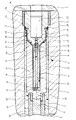
- This plasma torch 1 comprises an anode 2 and a cathode 3 separated by a capillary tube 4.
- the torch 1 generally has a symmetry of revolution. It is installed in a bore 5 fitted on a support 6, which is here a weapon (not shown in detail), weapon which comprises a tube 7 and a breech plate 8.
- the capillary 4 is made of an insulating material electric and susceptible to ablation, i.e. to generate light gases by the action of plasma.
- a plastic material such as polyethylene. It has an axial bore 9 to inside which a fuse is positioned (not shown), for example a copper wire.
- Anode 2 is constituted by a metal case which has a bottom 10 of reduced diameter and a body cylindrical 12.
- the bottom 10 is intended to receive an electrical contact 11 which is mechanically integral with the cylinder head plate 8.
- the cylindrical body 12 has an axial bore 13 to the interior of which houses the capillary 4 and a base 14 forming arc foot.
- the base 14 is made of a very conductive material and with high mechanical strength which has the function of limiting erosion due to the foot of the electric arc.
- It has a longitudinal channel 15 which makes it possible to evacuate the air trapped between the bottom 10 and the base 14 at the time of the installation of the latter, which makes it possible to apply the base 14 strongly against the bottom to ensure good contact electric.
- the capillary tube 4 is separated from the anode 2 by a cylindrical sheath 19, which is made of a material electrical insulation, for example a fiber-based composite of glass.
- This sheath is to provide insulation between the anode and the cathode.
- the open end of anode 2 has a conical profile 16 which is complementary to a conical bearing 17 arranged on cathode 3. This conical profile facilitates mounting of the cathode and ensures the coaxiality of these two parts.
- the insulating sheath 19 has a flared part 20 which is interposed between the conical bearing 17 of the cathode 3 and the conical housing 16 of the conductive case of anode 2 and avoids any electrical short circuit at this level between the anode and the cathode.
- the cathode 3 has an annular sealing lip 18 which is applied against the insulating sheath 19 and which delimits a bore receiving an end 21 with diameter reduced capillary 4.
- the lip 18 is intended to be deformed by the effect of the pressure of the plasma generated by the torch to prevent any plasma leak between the cathode 3 and the insulating sheath 19, leaks that would affect the efficiency of the torch and damage the electrical insulation.
- the cathode 3 In order to locate the base of the electric arc, the cathode 3 also includes an axial housing 22 in which is disposed a conductive ring 23 forming the arc foot. This ring is made of the same material as the base 14.
- the cathode 3 has an axial orifice 24 which makes communicate the interior of the torch with a chamber 25 intended to receive a projectile (not shown) and possibly a gas-generating material (for example the water).
- a projectile not shown
- a gas-generating material for example the water
- the flared part 20 of the insulating sheath 19 ends in a cylindrical portion 26 which surrounds the cathode 3.
- An insulating tubular sleeve 27 surrounds the anode 2 and secures it to cathode 3 by through radial screws 28.
- the sleeve 27 completes the electrical insulation between the anode and cathode.
- O-rings 29, 30, 31 are arranged between the sleeve 27 and the insulating sheath 19. They allow avoid the formation of an electric arc at the level of the games radial mounting.
- the current supply at the cathode is ensured by a contact ring 34 which remains integral with the support 6 and which carries at least two longitudinal tabs flexible 35.
- the sleeve 27 also includes an annular machining 32 which is intended to receive and guide a crown 33 secured to an insulating sheath 36 which surrounds the contact 11 and electrically isolates it from the cylinder head plate 8.
- a difference in electrical potential of around 20 kilo volts is applied between anode 2 and cathode 3.
- the electrical insulation is ensured by the sheath 36 surrounding the contact 11, the insulating sleeve 27, the seals O-rings 29, 30 and 31 and the insulating sleeve 19.
- anode and cathode are only connected to each other by the fuse placed inside the capillary 4.
- This fuse initiates an electric arc between anode and cathode, arc which is maintained and causes the ablation of the material of the capillary and the generation of a plasma that comes out of the torch 1 through the axial hole 24.
- the anode 2 proposed by the invention makes it possible to avoid any plasma leakage towards the rear of the torch (towards the contact 11).
- the cylindrical body 12 of the anode 2 surrounds the capillary 4 over its entire length. It ensures the maintenance radial of this one despite the strong pressures developed at inside the torch. This results in excellent hold mechanical torch with minimal radial bulk.
- the torch according to the invention can be used in the armament field for firing high-speed projectiles significant (greater than 2000 m / s).
Landscapes
- Engineering & Computer Science (AREA)
- Physics & Mathematics (AREA)
- Plasma & Fusion (AREA)
- Spectroscopy & Molecular Physics (AREA)
- General Engineering & Computer Science (AREA)
- Plasma Technology (AREA)
Abstract
Description
Claims (9)
- Torche à plasma (1) comprenant une anode (2) et une cathode (3) séparées par un tube capillaire (4) réalisé en un matériau isolant électrique et ablatable par l'action du plasma, torche caractérisée en ce que l'anode (2) comporte un étui conducteur (12) fermé à une première extrémité (10), étui à l'intérieur duquel est disposé le tube capillaire (4).
- Torche à plasma selon la revendication 1, caractérisée en ce que le tube capillaire (4) est séparé de l'anode (2) par un fourreau isolant (19).
- Torche à plasma selon la revendication 2, caractérisée en ce que l'étui de l'anode s'étend longitudinalement sensiblement jusqu'à la cathode (3), le fourreau isolant (19) entourant au moins partiellement la cathode (3).
- Torche à plasma selon la revendication 3, caractérisée en ce que la cathode (3) comporte une portée conique (17) qui vient se positionner dans un logement complémentaire conique (16) de l'étui conducteur, le fourreau isolant (19) comportant une partie évasée (20) qui est interposée entre la portée conique de la cathode et le logement conique (16) de l'étui conducteur.
- Torcha à plasma selon une des revendications 1 à 4, caractérisée en ce que l'anode (2) comporte un culot (14) formant pied d'arc disposé au fond de l'étui conducteur.
- Torche à plasma selon une des revendications 2 à 5, caractérisée en ce que la cathode (3) comporte une lèvre d'étanchéité annulaire (18) qui est appliquée contre le fourreau isolant (19) et qui délimite un alésage recevant une extrémité (21) à diamètre réduit du capillaire (4).
- Torche à plasma selon une des revendications 1 à 6, caractérisée en ce que la cathode (3) comporte un logement axial (22) dans lequel est disposé un anneau conducteur (23) formant pied d'arc.
- Torche à plasma selon une des revendications 1 à 7, caractérisée en ce qu'elle comporte un manchon tubulaire isolant (27) entourant l'anode (2) et assurant sa solidarisation avec la cathode (3).
- Torche à plasma selon la revendication 8, caractérisée en ce qu'elle comporte au moins un joint torique (29,30,31) disposé entre le manchon tubulaire (27) et le fourreau isolant (19).
Applications Claiming Priority (3)
| Application Number | Priority Date | Filing Date | Title |
|---|---|---|---|
| FR9612680A FR2754969B1 (fr) | 1996-10-18 | 1996-10-18 | Torche a plasma a etancheite amelioree |
| FR9612680 | 1996-10-18 | ||
| US08/954,036 US5938950A (en) | 1996-10-18 | 1997-10-20 | Plasma torch with improved gas-tightness |
Publications (2)
| Publication Number | Publication Date |
|---|---|
| EP0837621A1 true EP0837621A1 (fr) | 1998-04-22 |
| EP0837621B1 EP0837621B1 (fr) | 2003-02-19 |
Family
ID=26233049
Family Applications (1)
| Application Number | Title | Priority Date | Filing Date |
|---|---|---|---|
| EP97402414A Expired - Lifetime EP0837621B1 (fr) | 1996-10-18 | 1997-10-14 | Torche à plasma avec nouvelles caractéristiques d'étanchéité |
Country Status (3)
| Country | Link |
|---|---|
| US (1) | US5938950A (fr) |
| EP (1) | EP0837621B1 (fr) |
| FR (1) | FR2754969B1 (fr) |
Cited By (2)
| Publication number | Priority date | Publication date | Assignee | Title |
|---|---|---|---|---|
| CN111918473A (zh) * | 2020-07-27 | 2020-11-10 | 内蒙古东源科技有限公司 | 一种等离子体炬绝缘密封装置 |
| CN116669272A (zh) * | 2023-06-19 | 2023-08-29 | 南京理工大学 | 一种高温等离子体射流发生装置 |
Families Citing this family (10)
| Publication number | Priority date | Publication date | Assignee | Title |
|---|---|---|---|---|
| US6329628B1 (en) * | 1998-12-10 | 2001-12-11 | Polytechnic University | Methods and apparatus for generating a plasma torch |
| GB0011080D0 (en) * | 2000-05-08 | 2000-06-28 | Wang Wang N | Electrodes and plasma generating devices including electrodes |
| FR2827039B1 (fr) | 2001-07-06 | 2003-11-28 | Giat Ind Sa | Dispositif d'allumage pour un chargement propulsif |
| FR2844873B1 (fr) * | 2002-09-25 | 2006-11-24 | Giat Ind Sa | Inflammateur a double effet et procede d'allumage mettant en oeuvre un tel inflammateur |
| US6805055B1 (en) * | 2003-06-25 | 2004-10-19 | Gamma Recherches & Technologies Patent Sa | Plasma firing mechanism and method for firing ammunition |
| US7091441B1 (en) * | 2004-03-19 | 2006-08-15 | Polytechnic University | Portable arc-seeded microwave plasma torch |
| EP1689216A1 (fr) * | 2005-02-04 | 2006-08-09 | Vlaamse Instelling Voor Technologisch Onderzoek (Vito) | Jet de plasma à pression atmosphérique |
| SE533831C2 (sv) * | 2005-03-15 | 2011-02-01 | Bae Systems Bofors Ab | Plasmajettändare för en elektro-termisk-kemisk(ETK) kanon, kulspruta eller annat eldrörsvapen av motsvarande typ |
| CN102897892B (zh) * | 2012-10-26 | 2013-10-16 | 清华大学 | 一种增强型毛细管针放电等离子体水处理装置 |
| US11617610B2 (en) | 2018-04-26 | 2023-04-04 | Us Patent Innovations Llc | System and method for micro-sized cold atmospheric plasma treatment |
Citations (3)
| Publication number | Priority date | Publication date | Assignee | Title |
|---|---|---|---|---|
| EP0338458A1 (fr) * | 1988-04-18 | 1989-10-25 | Fmc Corporation | Arme de plasma à augmentation de combustion |
| US5287791A (en) * | 1992-06-22 | 1994-02-22 | Fmc Corporation | Precision generator and distributor device for plasma in electrothermal-chemical gun systems |
| GB2276801A (en) * | 1993-03-29 | 1994-10-05 | Fmc Corp | Multiple arc plasma initiating ignition/combustions in a cartridge for a projectile |
Family Cites Families (1)
| Publication number | Priority date | Publication date | Assignee | Title |
|---|---|---|---|---|
| US5261315A (en) * | 1991-11-04 | 1993-11-16 | Fmc Corporation | Precision capillary discharge switch |
-
1996
- 1996-10-18 FR FR9612680A patent/FR2754969B1/fr not_active Expired - Fee Related
-
1997
- 1997-10-14 EP EP97402414A patent/EP0837621B1/fr not_active Expired - Lifetime
- 1997-10-20 US US08/954,036 patent/US5938950A/en not_active Expired - Fee Related
Patent Citations (3)
| Publication number | Priority date | Publication date | Assignee | Title |
|---|---|---|---|---|
| EP0338458A1 (fr) * | 1988-04-18 | 1989-10-25 | Fmc Corporation | Arme de plasma à augmentation de combustion |
| US5287791A (en) * | 1992-06-22 | 1994-02-22 | Fmc Corporation | Precision generator and distributor device for plasma in electrothermal-chemical gun systems |
| GB2276801A (en) * | 1993-03-29 | 1994-10-05 | Fmc Corp | Multiple arc plasma initiating ignition/combustions in a cartridge for a projectile |
Cited By (2)
| Publication number | Priority date | Publication date | Assignee | Title |
|---|---|---|---|---|
| CN111918473A (zh) * | 2020-07-27 | 2020-11-10 | 内蒙古东源科技有限公司 | 一种等离子体炬绝缘密封装置 |
| CN116669272A (zh) * | 2023-06-19 | 2023-08-29 | 南京理工大学 | 一种高温等离子体射流发生装置 |
Also Published As
| Publication number | Publication date |
|---|---|
| EP0837621B1 (fr) | 2003-02-19 |
| FR2754969A1 (fr) | 1998-04-24 |
| FR2754969B1 (fr) | 1998-11-27 |
| US5938950A (en) | 1999-08-17 |
Similar Documents
| Publication | Publication Date | Title |
|---|---|---|
| EP0837621B1 (fr) | Torche à plasma avec nouvelles caractéristiques d'étanchéité | |
| EP1258695A1 (fr) | Culot pour munition destiné à recevoir un allumeur électrique | |
| US9118171B2 (en) | Electrical cable seal and method of making | |
| US9863813B2 (en) | Flame sensor | |
| FR2807610A1 (fr) | Torche a plasma incorporant un fusible d'amorcage reactif et tube allumeur integrant une telle torche | |
| US9006570B2 (en) | Sealing between an electrical cable and a flexible metal conduit to be used in a high temperature, high vibration environment | |
| EP0905470B1 (fr) | Composant d'allumage pour composition pyrotechnique ou charge propulsive | |
| FR2807611A1 (fr) | Torche plasma comportant des electrodes separees par un entrefer et allumeur incorporant une telle torche | |
| FR2897747A1 (fr) | Torche a plasma a arc transfere | |
| FR2724716A1 (fr) | Arme a tube. | |
| FR2952245A1 (fr) | Systeme de transmission de puissance electrique a travers une paroi | |
| US10361013B2 (en) | Triaxial mineral insulated cable in flame sensing applications | |
| US9530904B2 (en) | High temerature, hermetically sealed, triaxial mount for a light sensitive element | |
| US9933158B2 (en) | Underwater torch | |
| FR2590739A1 (fr) | Tete de cable, notamment pour cable a haute tension isole par de la matiere synthetique | |
| CN115696712A (zh) | 一种等离子体发生装置 | |
| EP0073168A2 (fr) | Torche pour coupage, soudage ou rechauffage | |
| EP1139701A1 (fr) | Torche à plasma avec amorçage par contact entre l'électrode et la tuyère | |
| FR2482480A1 (fr) | Pistolet de pulverisation electrostatique | |
| CH415812A (fr) | Générateur électrique magnétohydrodynamique comportant des électrodes continues et des moyens d'asservissement de ces électrodes | |
| FR2640090A1 (fr) | Dispositif formant eclateur comprenant un chemisage interieur en materiau refractaire electriquement isolant et appareil generateur d'ondes de choc, notamment pour la lithotritie hydraulique, pourvu d'un tel dispositif | |
| FR3140768A1 (fr) | Extincteur d’incendie de moteur | |
| FR3119506A1 (fr) | Dispositif de production d’un plasma comprenant une unité d’allumage de plasma | |
| FR2844873A1 (fr) | Inflammateur a double effet et procede d'allumage mettant en oeuvre un tel inflammateur | |
| FR2535431A1 (fr) | Structure pour etancher une tige de transmission de poussee mobile vers l'interieur et vers l'exterieur d'une cellule |
Legal Events
| Date | Code | Title | Description |
|---|---|---|---|
| PUAI | Public reference made under article 153(3) epc to a published international application that has entered the european phase |
Free format text: ORIGINAL CODE: 0009012 |
|
| AK | Designated contracting states |
Kind code of ref document: A1 Designated state(s): DE GB SE |
|
| 17P | Request for examination filed |
Effective date: 19981008 |
|
| AKX | Designation fees paid |
Free format text: DE GB SE |
|
| RBV | Designated contracting states (corrected) |
Designated state(s): DE GB SE |
|
| 17Q | First examination report despatched |
Effective date: 20001205 |
|
| GRAG | Despatch of communication of intention to grant |
Free format text: ORIGINAL CODE: EPIDOS AGRA |
|
| GRAG | Despatch of communication of intention to grant |
Free format text: ORIGINAL CODE: EPIDOS AGRA |
|
| GRAH | Despatch of communication of intention to grant a patent |
Free format text: ORIGINAL CODE: EPIDOS IGRA |
|
| GRAH | Despatch of communication of intention to grant a patent |
Free format text: ORIGINAL CODE: EPIDOS IGRA |
|
| GRAA | (expected) grant |
Free format text: ORIGINAL CODE: 0009210 |
|
| AK | Designated contracting states |
Designated state(s): DE GB SE |
|
| PG25 | Lapsed in a contracting state [announced via postgrant information from national office to epo] |
Ref country code: GB Free format text: LAPSE BECAUSE OF FAILURE TO SUBMIT A TRANSLATION OF THE DESCRIPTION OR TO PAY THE FEE WITHIN THE PRESCRIBED TIME-LIMIT Effective date: 20030219 |
|
| REG | Reference to a national code |
Ref country code: GB Ref legal event code: FG4D Free format text: NOT ENGLISH |
|
| REF | Corresponds to: |
Ref document number: 69719142 Country of ref document: DE Date of ref document: 20030327 Kind code of ref document: P |
|
| PG25 | Lapsed in a contracting state [announced via postgrant information from national office to epo] |
Ref country code: SE Free format text: LAPSE BECAUSE OF FAILURE TO SUBMIT A TRANSLATION OF THE DESCRIPTION OR TO PAY THE FEE WITHIN THE PRESCRIBED TIME-LIMIT Effective date: 20030519 |
|
| PG25 | Lapsed in a contracting state [announced via postgrant information from national office to epo] |
Ref country code: DE Free format text: LAPSE BECAUSE OF FAILURE TO SUBMIT A TRANSLATION OF THE DESCRIPTION OR TO PAY THE FEE WITHIN THE PRESCRIBED TIME-LIMIT Effective date: 20030520 |
|
| GBV | Gb: ep patent (uk) treated as always having been void in accordance with gb section 77(7)/1977 [no translation filed] |
Effective date: 20030219 |
|
| PLBE | No opposition filed within time limit |
Free format text: ORIGINAL CODE: 0009261 |
|
| STAA | Information on the status of an ep patent application or granted ep patent |
Free format text: STATUS: NO OPPOSITION FILED WITHIN TIME LIMIT |
|
| 26N | No opposition filed |
Effective date: 20031120 |