EP0838308A1 - Getriebekugelstrahlverfahren und getriebe - Google Patents
Getriebekugelstrahlverfahren und getriebe Download PDFInfo
- Publication number
- EP0838308A1 EP0838308A1 EP96923077A EP96923077A EP0838308A1 EP 0838308 A1 EP0838308 A1 EP 0838308A1 EP 96923077 A EP96923077 A EP 96923077A EP 96923077 A EP96923077 A EP 96923077A EP 0838308 A1 EP0838308 A1 EP 0838308A1
- Authority
- EP
- European Patent Office
- Prior art keywords
- tooth
- gear
- shot
- shots
- line
- Prior art date
- Legal status (The legal status is an assumption and is not a legal conclusion. Google has not performed a legal analysis and makes no representation as to the accuracy of the status listed.)
- Ceased
Links
- 238000005480 shot peening Methods 0.000 title claims abstract description 37
- 238000000034 method Methods 0.000 title claims abstract description 22
- 238000005422 blasting Methods 0.000 claims description 4
- 238000011144 upstream manufacturing Methods 0.000 claims description 4
- 230000015572 biosynthetic process Effects 0.000 abstract description 6
- 229910000831 Steel Inorganic materials 0.000 description 11
- 239000010959 steel Substances 0.000 description 11
- 238000005259 measurement Methods 0.000 description 8
- 230000008685 targeting Effects 0.000 description 6
- 230000003746 surface roughness Effects 0.000 description 3
- 238000010586 diagram Methods 0.000 description 2
- 238000012986 modification Methods 0.000 description 2
- 230000004048 modification Effects 0.000 description 2
- TVEXGJYMHHTVKP-UHFFFAOYSA-N 6-oxabicyclo[3.2.1]oct-3-en-7-one Chemical compound C1C2C(=O)OC1C=CC2 TVEXGJYMHHTVKP-UHFFFAOYSA-N 0.000 description 1
- PNEYBMLMFCGWSK-UHFFFAOYSA-N aluminium oxide Inorganic materials [O-2].[O-2].[O-2].[Al+3].[Al+3] PNEYBMLMFCGWSK-UHFFFAOYSA-N 0.000 description 1
- 239000011324 bead Substances 0.000 description 1
- 238000005256 carbonitriding Methods 0.000 description 1
- 230000007423 decrease Effects 0.000 description 1
- 239000011521 glass Substances 0.000 description 1
- 238000009434 installation Methods 0.000 description 1
- 238000004519 manufacturing process Methods 0.000 description 1
- 239000000463 material Substances 0.000 description 1
- 230000002093 peripheral effect Effects 0.000 description 1
- 229920006395 saturated elastomer Polymers 0.000 description 1
- 230000035939 shock Effects 0.000 description 1
- 238000004904 shortening Methods 0.000 description 1
- 238000005549 size reduction Methods 0.000 description 1
- 238000007669 thermal treatment Methods 0.000 description 1
Images


Classifications
-
- C—CHEMISTRY; METALLURGY
- C21—METALLURGY OF IRON
- C21D—MODIFYING THE PHYSICAL STRUCTURE OF FERROUS METALS; GENERAL DEVICES FOR HEAT TREATMENT OF FERROUS OR NON-FERROUS METALS OR ALLOYS; MAKING METAL MALLEABLE, e.g. BY DECARBURISATION OR TEMPERING
- C21D7/00—Modifying the physical properties of iron or steel by deformation
- C21D7/02—Modifying the physical properties of iron or steel by deformation by cold working
- C21D7/04—Modifying the physical properties of iron or steel by deformation by cold working of the surface
- C21D7/06—Modifying the physical properties of iron or steel by deformation by cold working of the surface by shot-peening or the like
-
- B—PERFORMING OPERATIONS; TRANSPORTING
- B24—GRINDING; POLISHING
- B24C—ABRASIVE OR RELATED BLASTING WITH PARTICULATE MATERIAL
- B24C1/00—Methods for use of abrasive blasting for producing particular effects; Use of auxiliary equipment in connection with such methods
- B24C1/10—Methods for use of abrasive blasting for producing particular effects; Use of auxiliary equipment in connection with such methods for compacting surfaces, e.g. shot-peening
-
- C—CHEMISTRY; METALLURGY
- C21—METALLURGY OF IRON
- C21D—MODIFYING THE PHYSICAL STRUCTURE OF FERROUS METALS; GENERAL DEVICES FOR HEAT TREATMENT OF FERROUS OR NON-FERROUS METALS OR ALLOYS; MAKING METAL MALLEABLE, e.g. BY DECARBURISATION OR TEMPERING
- C21D9/00—Heat treatment, e.g. annealing, hardening, quenching or tempering, adapted for particular articles; Furnaces therefor
- C21D9/32—Heat treatment, e.g. annealing, hardening, quenching or tempering, adapted for particular articles; Furnaces therefor for gear wheels, worm wheels, or the like
-
- Y—GENERAL TAGGING OF NEW TECHNOLOGICAL DEVELOPMENTS; GENERAL TAGGING OF CROSS-SECTIONAL TECHNOLOGIES SPANNING OVER SEVERAL SECTIONS OF THE IPC; TECHNICAL SUBJECTS COVERED BY FORMER USPC CROSS-REFERENCE ART COLLECTIONS [XRACs] AND DIGESTS
- Y10—TECHNICAL SUBJECTS COVERED BY FORMER USPC
- Y10T—TECHNICAL SUBJECTS COVERED BY FORMER US CLASSIFICATION
- Y10T29/00—Metal working
- Y10T29/47—Burnishing
- Y10T29/479—Burnishing by shot peening or blasting
Definitions
- the present invention relates to a shot peening method for blasting the external surface of a gear with small shots while rotating the gear to harden the external surface and relates to gears treated by such shot peening.
- Shot peening is a treatment for hardening the surfaces of objects such as gears by blasting their peripheral surfaces with shots such as steel balls by use of an impeller or nozzle.
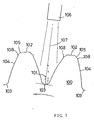
- FIG. 7 illustrates one example of shot peening utilizing a nozzle.
- shots 101 such as steel balls collide with the external surface of a gear 100.
- the gear 100 is so configured as to comprise (i) top lands 102, (ii) bottom lands 103, (iii) tooth flanks 104 each of which is formed, for example, by an involute curve extending from each bottom land 103 to each top land 102 and (iv) chamfers of tooth top 105 each positioned between each tooth flank 104 and each top land 102.
- the shots 101 are shot from a nozzle 106.
- the shooting direction 107 of the shots 101 from the nozzle 106 is substantially perpendicular to one of the bottom lands 103 of the gear 100 being rotated.
- Such a conventional shot peening method suffers from the problem that plastic deformation occurs in the tops of the teeth of the gear 100 and particularly on the ridge lines each of which is the intersection of each tooth flank 104 and each chamfer of tooth top 105, on account of the shock caused at the time of collisions of the shots 101, and this deformation leads to formation of small projections 108 on the tooth flanks 104.
- the projections 108 harm another gear which is in mesh with the gear 100, with the result that the service life of the gear is shortened.
- the gears come into mesh with each other, they make a noisy action owing to the presence of the projections 108.
- the present invention has been made for the purpose of overcoming the foregoing problems and therefore one of the objects of the invention is to provide a shot peening method for gears capable of hardening the surface of a gear without formation of projections on its tooth tops. Another object of the invention is to provide gears of high strength hardened by this shot peening method.
- the invention provides a shot peening method for gears for blasting the external surface of a gear with shots while rotating the gear to harden the external surface, the gear comprising top lands, bottom lands, tooth flanks each curving from each bottom land to each top land, and chamfers of tooth top each positioned between each tooth flank and each top land, the method comprising:
- the preliminary shot is performed so as to make the shots collide with the top of a tooth of the gear to harden the tooth top beforehand.
- the shots collide with the tooth top during the bottom land shot step no projections will be formed on the tooth top, so that a higher degree of hardening can be ensured.
- the shot peening method of the invention solves the problems of shortening the service life of the other of a pair of meshing gears and of a noise made when the gears come into mesh with each other.
- the shot peening method of the invention is preferably arranged such that, in a plane that crosses the axis of the gear at right angles, the target of shooting in the preliminary shot step is a ridge point that is the intersection of the chamfer line of tooth top and the tooth flank line, these lines being positioned in the upstream part of the tooth when viewing the tooth in the rotating direction of the gear, and such that the axis of a nozzle for the preliminary shot is positioned in an area between a bisector which bisects the interior angle of a corner having the ridge point as its intersection and a straight line which connects the ridge point and the apex of another tooth opposite to the ridge point.
- the neighbor part of the ridge point that is the intersection of the chamfer line and the tooth flank line, where projections are most likely to be formed is hardened and squeezed into a round shape or an obtuse angled shape.
- the formation of projections on the tooth face can be effectively restricted.
- the axis of the shooting direction for the shots is positioned beyond the bisector of the interior angle of the corner having the ridge point as its intersection, the striking force of the shots will be concentrated on the side of the tooth flank relative to the ridge line formed by the chamfer of tooth top and the tooth flank, increasing the likelihood of formation of a projection.
- the axis of the shooting direction is positioned beyond the straight line which connects the ridge point and the apex of another tooth which is opposite to the ridge point, this opposite tooth interferes with the shot targeting at the ridge point.
- the shot peening method of the invention may be arranged such that, in a plane that crosses the axis of the gear at right angles, the target of shooting in the preliminary shot step is a ridge point that is the intersection of the chamfer line of tooth top and the tooth flank line, these lines being positioned in the downstream part of the tooth when viewing the tooth in the rotating direction of the gear, and such that the axis of a nozzle for the preliminary shot is positioned in an area between a prolongation of the top land line and a prolongation of the chamfer line of tooth top of the downstream part.
- the shots will laterally collide with the ridge point at which the chamfer line intersects the tooth flank line adjacent the chamfer line, these lines being positioned in the downstream part of the tooth relative to the rotating direction of the gear. This is likely to cause formation of a projection on the tooth flank side relative to the ridge point. If the axis of the shooting direction is positioned beyond the prolongation of the top land line, the shot targeting at the ridge point, that is the intersection of the top land line and the chamfer line of the downstream part of the tooth, will be interfered with.
- a gear having an external surface which comprises top lands, bottom lands, tooth flanks each curving from each bottom land to each top land, and chamfers of tooth top each positioned between each tooth flank and each top land, the external surface of the gear being blasted with shots by shot peening which comprises:
- the gear according to the invention is treated by shot peening in which prior to "the bottom land shot” for shooting shots substantially perpendicularly to one of the bottom lands of the gear, the preliminary shot is performed so as to make the shots collide with the top of a tooth of the gear to harden the tooth top beforehand, so that there are no projections on the tooth tops of the gear.
- the gear of the invention is treated by shot peening arranged such that, in a plane that crosses the axis of the gear at right angles, the target of shooting in the preliminary shot step is a ridge point that is the intersection of the chamfer line of tooth top and the tooth flank line, these lines being positioned in the upstream part of the tooth when viewing the tooth in the rotating direction of the gear, and such that the axis of a nozzle for the preliminary shot is positioned in an area between a bisector which bisects the interior angle of a corner having the ridge point as its intersection and a straight line which connects the ridge point and the apex of another tooth opposite to the ridge point.
- the gear of the invention may be treated by shot peening arranged such that, in a plane that crosses the axis of the gear at right angles, the target of shooting in the preliminary shot step is a ridge point that is the intersection of the chamfer line of tooth top and the tooth flank line, these lines being positioned in the downstream part of the tooth when viewing the tooth in the rotating direction of the gear, and such that the axis of a nozzle for the preliminary shot is positioned in an area between a prolongation of the top land line and a prolongation of the chamfer line of tooth top of the downstream part.
- a gear having an external surface which comprises top lands, bottom lands, tooth flanks each curving from each bottom land to each top land, and chamfers of tooth top each positioned between each tooth flank and each top land, the external surface of the gear being blasted with shots by shot peening in which the arc height of a bottom land shot for shooting the shots substantially perpendicularly to one of the bottom lands is 0.6mmA or more, and the projecting amount of a projection created on each ridge line of each tooth flank and each chamfer of tooth top being 5 ⁇ or less.
- the projecting amount of a projection created on each ridge line formed by each tooth flank and each chamfer of tooth top is set to 5 ⁇ or less that is the allowable range required by considerations of the surface roughness of teeth.
- the arc height adopted in the invention is set to 0.6mmA or more which enables "hard shot peening" to provide a high compressive residual stress, so that high strength can be achieved. Accordingly, the gear of the invention is satisfactory as a product both in terms of strength and precision.
- Figures 1 to 6 are associated with a shot peening method for gears according to one preferred embodiment of the invention.
- Figure 1 is a partial side view illustrating a preliminary shot step according to the embodiment.
- Figure 2 is a partial side view illustrating another preliminary shot step according to the embodiment.
- Figure 3 is a partial side view illustrating a bottom land shot step according to the embodiment.
- Figure 4 is a schematic diagram illustrating an arrangement for performing the shot peening method for gears according to the embodiment.
- Figures 5(a) and 5(b) are graphs demonstrating the results of tests conducted on shot peening according to the embodiment.
- Figure 6 is a perspective view of a gear hardened by shot peening according to the embodiment.
- Figure 7 is a diagram illustrating a problem presented by a prior art method.
- Figure 1 is a partial side view illustrating a preliminary shot step for gears according to one embodiment of the invention.
- the external surface of a gear according to this embodiment has top lands 1, bottom lands 2, left involute faces 4a, right involute faces 4b and chamfers of tooth top 5a, 5b.
- the left and right involute faces 4a, 4b respectively curve from the bottom land 2 to the top land 1, forming the side faces of the tooth 3A and the chamfers of tooth top 5a, 5b are formed between the respective left and right involute faces 4a, 4b and the top land 1.
- an air nozzle 7 is so arranged as to shoot shots (which are steel balls in this embodiment) at a ridge line which is formed by the left involute face 4a and the chamfer of tooth top 5a (for simplicity, this ridge line is hereinafter referred to as "ridge point 6a" which exists within a profile, i.e., a plane crossing the axis of the gear at right angles). More specifically, the air nozzle 7 is arranged such that the axis 8 of a shot of the steel balls from the air nozzle 7 passes through the ridge point 6a.
- the axis 8 of the air nozzle 7 is positioned within an area between a bisector 9 which bisects the interior angle of a corner having the ridge point 6a as its intersection and a straight line 10 which connects the ridge point 6a and the apex of a tooth 3B facing the ridge point 6a.
- the gear shown in Figure 1 rotates counterclockwise, so that the ridge point 6a, the chamfer of tooth top 5a and the involute face 4a are moved and directed toward the air nozzle 7. It should be understood that Figure 1 depicts one instantaneous state of the gear.
- the tooth 3B will interfere with the shot targeting at the ridge point 6a.
- the axis 8 of the air nozzle 7 is arranged beyond the bisector 9 (i.e., positioned above the bisector 9 in Figure 1), the projection is likely to form in the area on the involute face 4a side relative to the ridge point 6a.
- the gear is turned over to perform the same preliminary shot on the reverse side, so that the right and left sides of the tooth 3A can be symmetrically hardened and uniformly improved in strength.
- Figure 2 shows another embodiment of the shooting direction of the air nozzle 7.
- the axis 8 of the air nozzle 7 passes through a ridge point 11 which is the intersection of the top land 1 and the right chamfer of tooth top 5b which is positioned downstream the left chamfer of tooth top 5a in the rotating direction of the gear.
- the axis 8 is arranged within the area between a prolongation 12 of the top land 1 and a prolongation 13 of the right chamfer 5b.
- Figure 2 also depicts one instantaneous state of the gear and in reality, the steel balls collide with the entire part of the tooth 3A.
- the axis 8 of the air nozzle 7 is arranged beyond the prolongation 12 (i.e., positioned under the prolongation 12 in Figure 2), the shot targeting at the ridge point 11 will be interfered with.
- the axis 8 of the air nozzle 7 is arranged beyond the prolongation 13 (i.e., positioned above the prolongation 13 in Figure 2), the projection is likely to form in the area on the right involute face 4b side relative to a ridge point 6b which is the intersection of the right chamfer of tooth top 5b and the right involute face 4b.
- the gear is preferably turned over to perform the same preliminary shot on the reverse side, so that the right and left sides of the tooth 3A can be symmetrically hardened and uniformly improved in strength.
- an air nozzle 7' is such arranged that its axis 8' becomes perpendicular to the bottom land 2 to perform a "bottom land shot".
- the gear is rotating during the bottom land shot and therefore the steel balls collide with all of the parts, i.e., the bottom lands 2, involute faces 4a, 4b, chambers of tooth top 5a, 5b and top land 1 with the result that the gear can be entirely hardened.
- the tooth top is hardened by the preliminary shot described earlier, no projections form on the tooth top during the bottom land shot.
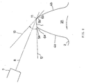
- Figure 4 shows the positional relationships between the gear and the air nozzles 7, 7'.
- the diameter of the gear is 105.88mm and the width of the shot of the steel balls 20 by the air nozzle 7 (the distance from the left end 21 of a shot area to the right end 22 thereof) is 20mm.
- the position of the air nozzle 7 is arranged such that the left end 21 of the shot area contact the leading end of a radius sector 24 of the gear, the radius sector 24 being at 34° to a radius sector 23 of the gear that makes a right angle with the axis 8 of the air nozzle 7.
- the distance between the axis 8 of the air nozzle 7 and the center 25 of the gear is 59mm.
- the position of the air nozzle 7 in relation to the gear is arranged for performing the preliminary shot described in conjunction with Figure 2.
- the air nozzle 7' designed to perform the bottom land shot is the same as the above-described air nozzle 7 in size and disposed in parallel with the air nozzle 7.
- the axis 8' of the air nozzle 7' for the bottom land shot passes through the center 25 of the gear and the distance between the axis 8' of the air nozzle 7' and the axis 8 of the air nozzle 7 is 59mm.
- the preliminary shot and the bottom land shot are both applied to the upper half of the gear shown in Figure 6 by use of the air nozzles 7 and 7' whereas only the bottom land shot is applied to the lower half of the gear by use of the air nozzle 7'.
- Shot peening was carried out with arc height (this is an index indicating the power of a shot) being varied and performed 10 times with the same arc height.
- Table 1 demonstrates the steps of the tests conducted on the upper half and lower half of the gear in order.
- MEASUREMENT OF TOOTH PROFILE PRECISION (1) MEASUREMENT OF TOOTH PROFILE PRECISION (2) PRELIMINARY SHOT (TARGETING AT LEFT SURFACE) (3) MEASUREMENT OF TOOTH PROFILE PRECISION (4) PRELIMINARY SHOT (TARGETING AT RIGHT SURFACE) (5) MEASUREMENT OF TOOTH PROFILE PRECISION (6) BOTTOM LAND SHOT (2) BOTTOM LAND SHOT (7) MEASUREMENT OF TOOTH PROFILE PRECISION (MEASUREMENT OF PROJECTING AMOUNT) (3) MEASUREMENT OF TOOTH PROFILE PRECISION (MEASUREMENT OF PROJECTING AMOUNT)
- the preliminary shot is performed with a stress of 2kg/cm 2 and steel balls are used as shots.
- This preliminary, shot is performed for the purpose of hardening the entire part of a tooth top evenly.
- the preferred preliminary shot is carried out with arc height which does not exceed the arc height of the bottom land shot in order not to impair the surface roughness of the tooth flanks.
- Figures 5(a) and 5(b) show the results of the tests in the case of the presence of the preliminary shot and in the case of the absence of the preliminary shot.
- Figure 5(a) is a graph showing the relationship between arc height, the maximum projecting amount at a tooth top and compressive residual stress
- Figure 5(b) is a graph showing the relationship between arc height and the average projecting amount at a tooth top.
- the allowable projecting amount at a tooth top is approximately 5 ⁇ which is obtained taking surface roughness into account. From this allowable amount, it is understood that no problems will practically arise if the preliminary shot is not performed when arc height is less than 0.6mmA. However, a compressive stress of 100kg/mm 2 or more (shown as minus value in Figure 5) is required in the case of hard shot peening in which a high compressive residual stress is applied to a gear to impart high strength to it. Converting this compressive stress into arc height, 0.6mmA or more is necessary. It means that when manufacturing strong gears with an arc height of 0.6mmA or more, the projecting amount at a tooth top is 5 ⁇ or more and therefore application of the preliminary shot according to this embodiment is indispensable. Theoretically, preliminary shot is useful when arc height exceeds 1.0mmA, but in practice, it is usual to perform shot peening with an arch height of no more than 1.0mmA with which a compressive residual stress is saturated.
- the foregoing embodiment employs the air nozzle 7' for the bottom land shot in addition to the air nozzle 7 used for the preliminary shot.
- the air nozzle 7 for the preliminary shot may be used for the bottom land shot as well in one shot peening system by changing the installation angle of the air nozzle 7.
- the gear is turned over in the preliminary shot step in order to uniformly harden the right and left sides of the gear in the foregoing embodiment, there may be disposed two air nozzles 7 one of which is for shooting at the left side face of the gear and the other of which is for shooting at the right side face of the same. It is also possible to shift the shooting direction of one air nozzle so as to make the preliminary shot from both the right and left sides.
- steel balls are used as the shots in the foregoing embodiment, glass beads, alumina balls or super hard balls may be used in place of steel balls.
- size of the shots used in the preliminary shot but shots having a diameter of 1.2mm or less are generally used.
- the shape adopted for the profile of each side of a tooth is an involute curve in the foregoing embodiment, the shape of the sides is not particularly limited to this, but may take various shapes such as cycloid curves and straight lines.
Landscapes
- Engineering & Computer Science (AREA)
- Chemical & Material Sciences (AREA)
- Mechanical Engineering (AREA)
- Crystallography & Structural Chemistry (AREA)
- Materials Engineering (AREA)
- Metallurgy (AREA)
- Organic Chemistry (AREA)
- Gear Processing (AREA)
- Gears, Cams (AREA)
Applications Claiming Priority (3)
| Application Number | Priority Date | Filing Date | Title |
|---|---|---|---|
| JP17777995 | 1995-07-13 | ||
| JP177779/95 | 1995-07-13 | ||
| PCT/JP1996/001951 WO1997002925A1 (fr) | 1995-07-13 | 1996-07-10 | Procede de grenaillage d'ecrouissage de pignon et pignon ainsi obtenu |
Publications (2)
| Publication Number | Publication Date |
|---|---|
| EP0838308A1 true EP0838308A1 (de) | 1998-04-29 |
| EP0838308A4 EP0838308A4 (de) | 1999-06-02 |
Family
ID=16036969
Family Applications (1)
| Application Number | Title | Priority Date | Filing Date |
|---|---|---|---|
| EP96923077A Ceased EP0838308A4 (de) | 1995-07-13 | 1996-07-10 | Getriebekugelstrahlverfahren und getriebe |
Country Status (5)
| Country | Link |
|---|---|
| US (1) | US5911780A (de) |
| EP (1) | EP0838308A4 (de) |
| KR (1) | KR100392465B1 (de) |
| CN (1) | CN1190918A (de) |
| WO (1) | WO1997002925A1 (de) |
Cited By (2)
| Publication number | Priority date | Publication date | Assignee | Title |
|---|---|---|---|---|
| EP1174217A1 (de) * | 2000-07-18 | 2002-01-23 | Kai Motors Corporation | Verfahren zum Erhöhen der Ermüdungsfestigkeit von Zahnrädern durch Kugelstrahlhärten |
| EP1473489A1 (de) * | 2003-04-23 | 2004-11-03 | Toyoda Koki Kabushiki Kaisha | Apparatus und Herstellungsverfahren eines Differentialgetriebes für Fahrzeuge mit einem Planetengetriebe |
Families Citing this family (14)
| Publication number | Priority date | Publication date | Assignee | Title |
|---|---|---|---|---|
| RU2130085C1 (ru) * | 1997-05-29 | 1999-05-10 | Казаков Владимир Михайлович | Способ поверхностного упрочнения деталей |
| JP2000126929A (ja) * | 1998-10-23 | 2000-05-09 | Univ Saga | 歯車高品質化処理システムおよび該システムに用い得るバレル処理装置 |
| EP1555329A1 (de) | 2004-01-15 | 2005-07-20 | Siemens Aktiengesellschaft | Bauteil mit Druckeigenspannungen, Verfahren zur Herstellung und Vorrichtung zur Erzeugung von Druckeigenspannungen |
| US7156628B2 (en) * | 2004-06-03 | 2007-01-02 | White Drive Products, Inc. | Wobblestick with helix |
| US8062094B2 (en) * | 2005-06-29 | 2011-11-22 | Deere & Company | Process of durability improvement of gear tooth flank surface |
| CA2709474C (en) * | 2009-07-14 | 2016-04-26 | Engineered Abrasives, Inc. | Peen finishing |
| US10086483B2 (en) * | 2015-06-29 | 2018-10-02 | Engineered Abrasives, Inc. | Apparatus and method for processing a workpiece |
| US10895285B2 (en) * | 2015-07-27 | 2021-01-19 | Ford Global Technologies, Llc | Torque converter installation assist |
| US10378612B2 (en) * | 2016-03-08 | 2019-08-13 | GM Global Technology Operations LLC | Bevel gear set and method of manufacture |
| US20180257197A1 (en) * | 2017-03-08 | 2018-09-13 | Ford Motor Company | Method and apparatus for localized gear tooth root fillet shot peening |
| JP6904308B2 (ja) * | 2018-06-05 | 2021-07-14 | 新東工業株式会社 | ブラスト加工方法 |
| JP7077906B2 (ja) | 2018-10-12 | 2022-05-31 | トヨタ自動車株式会社 | 歯車の製造方法 |
| JP7188243B2 (ja) * | 2019-04-04 | 2022-12-13 | マツダ株式会社 | ハイポイドギヤの製造方法 |
| CN114555979A (zh) * | 2019-10-23 | 2022-05-27 | 住友电工烧结合金株式会社 | 齿轮部件 |
Family Cites Families (7)
| Publication number | Priority date | Publication date | Assignee | Title |
|---|---|---|---|---|
| JPS627245A (ja) * | 1985-07-04 | 1987-01-14 | Nec Corp | ロ−カルエリアネツトワ−クの端末通信方式 |
| JPH04107209A (ja) * | 1990-08-24 | 1992-04-08 | Nissan Motor Co Ltd | ショットピーニング方法 |
| JP3238431B2 (ja) * | 1991-07-31 | 2001-12-17 | マツダ株式会社 | 歯車部品のショットピーニング方法 |
| JPH06172850A (ja) * | 1992-12-09 | 1994-06-21 | Nippon Steel Corp | 歯車歯元の残留応力付与装置 |
| JPH06172851A (ja) * | 1992-12-09 | 1994-06-21 | Nippon Steel Corp | 歯車歯元の残留応力付与装置 |
| JPH06172852A (ja) * | 1992-12-09 | 1994-06-21 | Nippon Steel Corp | 歯車歯元の残留応力付与装置 |
| JP3438274B2 (ja) * | 1993-01-11 | 2003-08-18 | 日産自動車株式会社 | 歯車のショットピーニング装置 |
-
1996
- 1996-07-10 EP EP96923077A patent/EP0838308A4/de not_active Ceased
- 1996-07-10 WO PCT/JP1996/001951 patent/WO1997002925A1/ja not_active Ceased
- 1996-07-10 KR KR1019970704635A patent/KR100392465B1/ko not_active Expired - Fee Related
- 1996-07-10 CN CN96195506A patent/CN1190918A/zh active Pending
- 1996-07-10 US US08/875,103 patent/US5911780A/en not_active Expired - Lifetime
Non-Patent Citations (2)
| Title |
|---|
| No further relevant documents disclosed * |
| See also references of WO9702925A1 * |
Cited By (2)
| Publication number | Priority date | Publication date | Assignee | Title |
|---|---|---|---|---|
| EP1174217A1 (de) * | 2000-07-18 | 2002-01-23 | Kai Motors Corporation | Verfahren zum Erhöhen der Ermüdungsfestigkeit von Zahnrädern durch Kugelstrahlhärten |
| EP1473489A1 (de) * | 2003-04-23 | 2004-11-03 | Toyoda Koki Kabushiki Kaisha | Apparatus und Herstellungsverfahren eines Differentialgetriebes für Fahrzeuge mit einem Planetengetriebe |
Also Published As
| Publication number | Publication date |
|---|---|
| EP0838308A4 (de) | 1999-06-02 |
| KR19980701246A (ko) | 1998-05-15 |
| CN1190918A (zh) | 1998-08-19 |
| US5911780A (en) | 1999-06-15 |
| KR100392465B1 (ko) | 2003-10-23 |
| WO1997002925A1 (fr) | 1997-01-30 |
Similar Documents
| Publication | Publication Date | Title |
|---|---|---|
| US5911780A (en) | Gear shot peening method | |
| US6371875B2 (en) | Random engagement roller chain sprocket with cushion rings and root relief for improved noise characteristics | |
| US7892127B2 (en) | Power transmission chain and power transmission device | |
| JPS6314215B2 (de) | ||
| JPH0454350A (ja) | 低騒音チェーン及びチェーン伝動装置 | |
| US8813599B2 (en) | Gear structure | |
| US7874952B2 (en) | Power transmission chain and power transmission device | |
| KR100373280B1 (ko) | 에어노즐 숏피이닝을 이용한 기어가공방법 | |
| US5458023A (en) | Flexing contact type gear drive of non-profile-shifted two-circular-arc composite tooth profile | |
| JP4201784B2 (ja) | 直噴型エンジン用サイレントチェーン | |
| US5397278A (en) | Sprocket for roller chain | |
| GB2352793A (en) | Helical or spur gear drive with double crowned pinion tooth surfaces and conjugated gear tooth surfaces | |
| JP2938390B2 (ja) | 歯車のショットピーニング方法および歯車 | |
| CN203960268U (zh) | 一种齿轮齿面喷丸强化装置 | |
| TWI814418B (zh) | 高精度齒輪的加工方法 | |
| US12158200B2 (en) | Gear pair | |
| JP3835910B2 (ja) | 歯車のショットピーニング方法およびそれにより得られる高強度歯車 | |
| JPH05231500A (ja) | チェーン用スプロケット | |
| CN204403319U (zh) | 一种弧齿轮及弧齿条 | |
| CN104500695A (zh) | 弧齿轮及弧齿条 | |
| KR100438684B1 (ko) | 하모닉 감속기 | |
| JP2006206975A (ja) | 焼結ギヤ部材の製造方法 | |
| CA1312319C (en) | Screw rotor mechanism with thermal, safety and coating sensitive fit | |
| JPH04115868A (ja) | Cvtブロックの強度向上方法 | |
| JPH05169324A (ja) | 高強度ハイポイド歯車 |
Legal Events
| Date | Code | Title | Description |
|---|---|---|---|
| PUAI | Public reference made under article 153(3) epc to a published international application that has entered the european phase |
Free format text: ORIGINAL CODE: 0009012 |
|
| 17P | Request for examination filed |
Effective date: 19980212 |
|
| AK | Designated contracting states |
Kind code of ref document: A1 Designated state(s): DE GB IT |
|
| A4 | Supplementary search report drawn up and despatched |
Effective date: 19990421 |
|
| AK | Designated contracting states |
Kind code of ref document: A4 Designated state(s): DE GB IT |
|
| RIC1 | Information provided on ipc code assigned before grant |
Free format text: 6B 24C 1/10 A, 6B 24C 1/04 B |
|
| 17Q | First examination report despatched |
Effective date: 20001109 |
|
| GRAG | Despatch of communication of intention to grant |
Free format text: ORIGINAL CODE: EPIDOS AGRA |
|
| STAA | Information on the status of an ep patent application or granted ep patent |
Free format text: STATUS: THE APPLICATION HAS BEEN REFUSED |
|
| 18R | Application refused |
Effective date: 20020301 |