EP0838372A1 - Hilfsvorrichtung zum Beladen eines Kofferraums eines Kraftfahrzeuges - Google Patents
Hilfsvorrichtung zum Beladen eines Kofferraums eines Kraftfahrzeuges Download PDFInfo
- Publication number
- EP0838372A1 EP0838372A1 EP97402208A EP97402208A EP0838372A1 EP 0838372 A1 EP0838372 A1 EP 0838372A1 EP 97402208 A EP97402208 A EP 97402208A EP 97402208 A EP97402208 A EP 97402208A EP 0838372 A1 EP0838372 A1 EP 0838372A1
- Authority
- EP
- European Patent Office
- Prior art keywords
- roller
- trunk
- rear wall
- arm
- vehicle
- Prior art date
- Legal status (The legal status is an assumption and is not a legal conclusion. Google has not performed a legal analysis and makes no representation as to the accuracy of the status listed.)
- Granted
Links
- 238000005096 rolling process Methods 0.000 claims description 8
- 230000000903 blocking effect Effects 0.000 claims description 4
- 239000000463 material Substances 0.000 claims description 4
- XLYOFNOQVPJJNP-UHFFFAOYSA-N water Substances O XLYOFNOQVPJJNP-UHFFFAOYSA-N 0.000 claims description 3
- 239000011248 coating agent Substances 0.000 claims description 2
- 238000000576 coating method Methods 0.000 claims description 2
- 238000005253 cladding Methods 0.000 description 2
- 230000004308 accommodation Effects 0.000 description 1
- 238000010586 diagram Methods 0.000 description 1
- 230000013011 mating Effects 0.000 description 1
- 238000010079 rubber tapping Methods 0.000 description 1
Images



Classifications
-
- B—PERFORMING OPERATIONS; TRANSPORTING
- B60—VEHICLES IN GENERAL
- B60R—VEHICLES, VEHICLE FITTINGS, OR VEHICLE PARTS, NOT OTHERWISE PROVIDED FOR
- B60R5/00—Compartments within vehicle body primarily intended or sufficiently spacious for trunks, suit-cases, or the like
- B60R5/04—Compartments within vehicle body primarily intended or sufficiently spacious for trunks, suit-cases, or the like arranged at rear of vehicle
-
- B—PERFORMING OPERATIONS; TRANSPORTING
- B60—VEHICLES IN GENERAL
- B60R—VEHICLES, VEHICLE FITTINGS, OR VEHICLE PARTS, NOT OTHERWISE PROVIDED FOR
- B60R5/00—Compartments within vehicle body primarily intended or sufficiently spacious for trunks, suit-cases, or the like
Definitions
- the present invention relates to a device for assisting with loading a trunk of a motor vehicle.
- the object of the present invention is to eliminate this disadvantage by proposing a device to help the loading of a motor vehicle boot fitted with so as to considerably limit the effort required to a person to load or unload the trunk.
- the device according to the invention is characterized in that it comprises at least one element roller disposed near the upper edge of the wall defining the rear of the boot and allowing drag objects into it in the trunk.
- the device comprises several rolling elements constituted by rollers vertical fixed in the thickness of a piece of inner lining covering the rear wall of the chest.
- the rolling element is a roller with a substantially horizontal axis mounted on the rear wall of the boot substantially transversely to the center line of the vehicle.
- the roller is mounted so as to occupy a retracted inactive position or a position active use.
- the roller is supported at each of its ends on an arm fixed to the rear wall of the boot pivotally in a vertical plane between the two active and inactive positions mentioned above.
- the device advantageously comprises means for locking the roller in its active position of use.
- these means of locking include at least one forming element cleat mounted on the rear wall of the trunk and capable of slide or tilt to a position transverse to the arm corresponding swivel roller support so that block this arm in a vertical position for using the roller.
- the means of locks include at least one bolt member mounted on the rear wall of the boot and comprising a beveled end on which can bear the corresponding swivel arm when lifting the roller to its active position of use so as to retract the pin-forming element against the restoring force of a spring transversely to the movable arm which is then blocked in vertical position of use of the roller by return of the bolt-forming element in transverse position of the movable arm.
- the roller is mounted on the rear wall of the trunk through of two inverted U-shaped pieces arranged on the side and on the other side of the roller whose axis is fixed to each end at the connecting part of the two branches of the corresponding inverted U-shaped part, which branches can slide respectively in two horizontal parallel grooves forming guide rails so that by pulling up on the roller from its retracted position, the parts in the shape of an inverted U pass, by sliding in the grooves, from a horizontal position lying at a vertical position substantially perpendicular to the roller and to which the two U-shaped pieces overturned, released from their grooves, come to rest, by the free ends of their branches, on horizontal shouldered parts parallel to the axis of the vehicle to keep the roller in active position of use.
- the roller is fixed at the two ends of its axis respectively to two vertical legs that can slide vertically between the retracted position of the roller and its high position of use to which it is held by two buttons pressure each engaging elastically and transversely to the axis of the vehicle in a hole of the corresponding support leg which can be each manually inserted into the rear wall of the boot to allow the roller to descend to its retracted position.
- Each rolling element is located inside the trunk of the vehicle.
- the roller is housed in the retracted position in a form made in the rear wall of the trunk, preferably in an interior cladding piece covering this wall.
- each rolling element is covered non-slip material.
- the roller is fixed permanently in a housing made in a room of interior lining of the trunk covering the wall rear of it, this housing being preferably in form of hollow half-cylinder with vertical walls semicircular extremes are crossed by the axis of the roller to support it horizontally.
- the hollow semi-cylindrical housing aforementioned has one of its walls substantially horizontal and rounded at its edge to allow water drainage.
- the device can include two rollers mounted on either side of the bolt or strike bolt the rear opening of the boot.
- the device can include several rollers fixed in series to each other by intermediate pieces each in the form of a disc comprising on either side of the disc two coaxial lugs serving as support axes two adjacent rollers and integral arms respectively intermediate parts allowing attach these to the rear wall of the boot.
- Each roller can have the shape of a cylinder with tapered or beveled end, barrel or diabolo.
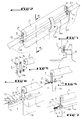
- Figure 1 is a partial perspective view of the rear part of a motor vehicle trunk comprising a device, in the retracted inactive position, to facilitate the loading of the next trunk a first embodiment of the invention.
- Figure 2 is a perspective view similar to that of Figure 1 and representing the device the invention in the active position of use.
- Figure 3 is a sectional view along line III-III in Figure 2.
- Figure 4 is an exploded view showing the attachment of one end of a roller of the device of FIGS. 1 to 3 at the rear wall of the vehicle boot.
- Figure 5 shows in perspective a mode of realization of a means of blocking one end of the loading roller of figures 1 to 4 in position of use.
- Figure 6 shows in perspective another mode of realization of such a locking means.
- Figure 7 shows a third embodiment another means of locking the loading roller in position of use.
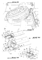
- Figure 8 shows in perspective the application of device of FIGS. 1 to 4 for the unloading of a vehicle spare wheel.
- FIG. 9 represents a second embodiment of the device of the invention including the loading roller is in the retracted position.
- Figure 10 shows the loading roller of the device of Figure 9 in an intermediate position to those retracted and using this roller.
- Figure 11 is a perspective view of one end of the device loading roller of FIGS. 9 and 10 in use position.
- Figure 12 is a perspective view showing a third embodiment of the invention with a roller to facilitate the loading of the vehicle trunk.
- Figure 13 is a partial sectional view along the line XIII-XIII of figure 12.
- Figure 14 shows in perspective a fourth mode of the device of the invention where the roller load is integrated into the rear wall of the boot vehicle.
- Figure 15 is a sectional view along line XV-XV in Figure 14.
- Figure 16 is a perspective view of the rear of a vehicle whose trunk includes a device for unloading with two separate rollers and a caster central between them.
- Figure 17 is a perspective view of the rear of a vehicle whose trunk includes three rollers mounted in series.
- Figure 18 is an exploded view showing how of which two adjacent series rollers of Figure 17.
- FIG. 19 represents an alternative embodiment of the shaped like a funnel-shaped roller.
- Figure 20 shows the assembly of the roller of the Figure 19 on the rear wall of the vehicle trunk.
- Figures 21 to 23 show other forms of realization of a roller which can be used in the loading device of the invention.
- Figure 24 partially shows a perspective fifth embodiment of the device the invention making it easier to load a vehicle trunk.
- Figures 1 to 4 show the first mode of realization of the device of the invention allowing assist a person loading a trunk 1 of a motor vehicle by objects 2, such as baggage, or when unloading it from the trunk 1.
- This device comprises a rolling element 3 constituted by a horizontal roller substantially transverse to the axis longitudinal of the vehicle and assembled to a wall vertical 4 delimiting the rear part of the trunk 1 of so as to occupy a retracted inactive position in the wall 4 or an active position of use at which the roller 3 is arranged in the vicinity of the upper edge 4a of wall 4, at least slightly above it to allow sliding, by rotation of the roller 3 around its longitudinal axis, baggage 2 in the trunk 1 when loading it.
- a rolling element 3 constituted by a horizontal roller substantially transverse to the axis longitudinal of the vehicle and assembled to a wall vertical 4 delimiting the rear part of the trunk 1 of so as to occupy a retracted inactive position in the wall 4 or an active position of use at which the roller 3 is arranged in the vicinity of the upper edge 4a of wall 4, at least slightly above it to allow sliding, by rotation of the roller 3 around its longitudinal axis, baggage 2 in the trunk 1 when loading it.
- roller 3 To allow the roller 3 to move from its position retracted to its position of use or vice versa, it is supported at each end 3a of its axis by an arm 5 whose end opposite to that bearing the axis of the roller 3 is rotatably mounted in the wall 4 around an axis transverse to the axis of the vehicle so that the two arms 5 pivot together in a vertical plane parallel to the center line of the vehicle.
- the roller 3 In the inactive position, the roller 3 is retracted into a transverse recessed part 4b for receiving the roller 3 made in the wall 4 below the upper edge 4a of it.
- the wall 4 has two parallel notches 4c to the center line of the vehicle, leading to the edge 4a of the wall 4 and each delimited by a wall 4d delimiting also the hollowed out part 4b and on which is mounted rotating the corresponding end of the movable arm 5.
- Figure 4 shows an example of mounting the roller 3 to the rear wall 4 via each arm 5.
- each threaded end 3a of the axis of the roller 3 crosses a bore 5a of the corresponding end of the swivel arm 5 and is held therein by a cap nut 6 of which the cylindrical part 6a, in which is carried out the receiving tapping of the threaded end, engages practically without play in this piercing.
- the other end of the arm 5 is fixed to the corresponding wall 4d via a part 7 integral with this wall and having one end threaded 7a passing through the bore 5b of the end arm 5 and a cap nut 8, the part of which cylindrical 8a, in which the thread of reception of the end 7a, engages practically without clearance in the hole 5b.
- the wall 4 has a 4th notch allowing the passage of at least one finger of a person to lift the roller 3 from its position retracted shown in this figure at its position usage record shown in Figure 2.
- FIG. 5 represents an embodiment of a means to lock the roller 3 in its position active use.
- This locking means is consisting of a cleat element 9 mounted to tilt in a plane substantially perpendicular to the axis of the vehicle between a retracted position in a groove of conjugate form 10 formed in the outer edge 4a of the wall 4 and a locking position of the movable arm 5 to its substantially vertical position.
- the cleat element 9 occupies a horizontal position transverse to arm 5 while being in support in the vicinity of the lower end of the arm 5 of to prevent it from rotating in the direction of tilting of the roller 3 towards its retracted position.
- a groove 11 is made in the upper edge 4a of the wall 4 in extension of groove 10 on the other side of the projection 4c so as to receive the end corresponding of the cleat element 9 in position folded arm lock 5.
- a other locking means as shown in figure 5 can be used to block the other arm 5 in vertical position.
- FIG. 6 represents an alternative embodiment of the locking means of FIG. 5 and according to which the cleat element 9 is slidably mounted in the groove 10 transversely to the axis of the vehicle between a retracted position in groove 10 and a position of blocking of the corresponding arm 5 to which a part end of the cleat element 9 rests in the other opposite groove 11.
- Figure 7 shows another embodiment of a arm locking means corresponding to its 5 vertical position of use of the roller 3.
- This locking means comprises a bolt-forming element 12 can slide transversely to the vehicle axis from an extended position crossing the notch corresponding 4c of passage of the movable arm 5 to a retracted position in a mating housing 13 of wall 4 against the return force of a spring 14 housed in this recess.
- the bolt element 12 has its end 12a bevelled so that during pivoting from arm 5 towards its vertical position, it comes in support on the bevelled part 12a to retract the pin forming element 12 in its housing 13 or move aside this element of his passage.
- the element forming bolt 12 returns to the out position of its housing 13 by the action of the spring 14 to block the arm 5 at this position.
- the person moves manually the bolt member 12 in its position retracted to free the passage notch 4c from the arm 5.
- Figure 8 shows the application of the roller device 3 of Figures 1 to 4 for unloading a spare wheel 15 trunk 1 using a strap 16 located under the wheel and can be gripped manually to lift it and put it on roller 3 and extract it as well easily from the trunk 1.
- Figures 9 to 11 show a second mode of realization of the device of the invention allowing the roller 3 to move from its retracted position to its position of use or vice versa by simple pull.
- the roller 3 is assembled to the rear wall 4 trunk 1 via two shaped parts of inverted U 17, of which only one is represented, arranged on either side of the roller 3 whose axis 3a is attached at each of its ends to the part of connection 17a of the two branches 17b of the part in the form of U reversed corresponding 17.
- each inverted U-shaped piece 17 has their ends comprising two coaxial lugs 17c making protrude outside of these branches so as to engage respectively in two parallel grooves horizontal 18 forming guide rails, arranged transversely to the center line of the vehicle and each carried out in a vertical wall 4f of the upper edge 4a of the wall 4, the two vertical walls 4f defining a horizontal recessed part for example substantially in coated U-shape 19 for receiving the part in corresponding U-shape 17 in inactive position retracted from the roller 3 in a corresponding housing 20.
- Each hollowed out part 19 leads to the housing 20, of which a vertical wall 20a located directly above the edge end of the housing 19 has a part horizontal 20b, arranged parallel to the axis of the vehicle and on which the two come to rest ends of the branches 17b of the U-shaped part overturned corresponding 17 when the roller 3 is in position of use.
- the two inverted U-shaped parts 17 are lying horizontally in their respective recessed parts 19 and when the roller 3 must be brought to its position of use, the person pulls it up so as to slide the ends simultaneously branches 17b of inverted U-shaped parts 17 in the corresponding grooves 18 until the two parts 17 leave their hollowed out parts 19 to find in a vertical position substantially perpendicular to the axis of the roller 3 and to which the free ends of the branches 17b of these parts 17 come to rest on their horizontal parts 20b to be held vertically and support the roller 3a in the use position.
- each groove 18 comprises in the vicinity of its middle a recess 18a which allows an intermediate positioning of the corresponding U-shaped part 17.
- the offset 18a is not symmetrical and its front part is vertical to block the U-shaped part 17.
- Figures 12 and 13 show a third mode of realization of the invention of a roller device to facilitate the loading of the trunk 1 of the motor vehicle.
- the roller 3 is fixed to the two ends of its axis respectively by two legs vertical 21, only one of which is shown, capable of slide vertically with respect to the rear wall 4 between a retracted position in the housing corresponding 22 transverse to the defined vehicle axis in wall 4 in particular by two vertical walls extremes 22a parallel to the axis of the vehicle and along which slide the two legs respectively support 21 of the roller 3.
- the two legs 21 can engage respectively in two grooves vertical 22b made at the bottom of the housing of this roller.
- Each press button 23 is thus housed, in the retracted position of the roller 3 in the wall 4, in a blind hole 24 in wall 4 with interposition of a spring 25 between the press button 23 and the bottom of the blind hole 24 and tending to repel the push button 23 outwards.
- Each press button 23 is held in the blind hole 24 by the corresponding tab 21 as long as the roller 3 does not not in its high position of use.
- each support tab 21 comes opposite the corresponding press button 23 which then engages elastically in this hole to block each tab in the position of use of the roller.
- the person press each press button 23 with its finger into its blind hole 24 to unlock the corresponding tab and push the roller 3 into its housing 22.
- Figures 14 and 15 show a fourth mode of realization of the device of the invention according to which the roller 3 is permanently fixed or integrated in a housing hollow semi-cylindrical 26 transverse to the axis of the vehicle and made in a piece of interior lining in plastic material 27 covering the rear wall of the trunk 1.
- Roll 3 which in this case is located inside the trunk 1 of the vehicle, is fixed in the semi-cylindrical housing 26 by fixing screws 28 joining the ends of the axis of the roller 3 respectively to the two vertical end walls semi-circular of this housing.
- Figure 15 shows that the semi-cylindrical housing 26 has its bottom wall substantially horizontal which is rounded at its edge for allow water drainage.
- roller 3 described in the other modes of previous achievement can also be housed retracted into an interior cladding room covering the rear wall 4 of the trunk 1.
- FIG. 16 represents an alternative embodiment according to which two rollers 3 are mounted on either side of the bolt or strike plate for locking the opening trunk 1 at the rear wall 4 thereof.
- Each roll 3 can be mounted to the wall 4 according to any one of previously described embodiments and, in addition, a central caster 29 can be fixed to the wall 4 between the two rollers 3 while being mounted vertically in a plane parallel to the axis of the vehicle.
- This mode of realization is useful when the interior of the trunk 1, more precisely the rear wall 4 delimiting the latter, is not straight and the presence of the central wheel 29 between the two rollers 3 facilitates loading or unloading of heavy and bulky objects.
- Figures 17 and 18 show an alternative embodiment that multiple rollers 3 are attached together in series with the rear wall 4 of the trunk 1.
- two adjacent rollers 3 are assembled together by a disc-shaped intermediate piece 30 comprising on each side of each disc two coaxial pins 31 serving as support axes of the two rollers 3 by engaging in two holes 3b respectively of the two adjacent rollers 3 produced coaxial to the longitudinal axis of each roller.
- rubber seals 32 can be fitted respectively on the two pins 31 of a disc 30 between it and the corresponding end face of the roller 3.
- Arms 33 secured respectively to support discs 30 rollers 3 allow to fix these at the rear wall 4 of the trunk 1. This mode of realization suitable for vehicles with style particular.
- Figures 19 to 23 show various forms of possible realization of a roller 3 which can be used in the previous embodiments.
- the roller 3 of Figure 19 has one 3c of its ends tapered or funnel-shaped and can be mounted lives in a corresponding accommodation 34 made in the upper edge of the rear wall 4 of said trunk as shown in Figure 20.
- the roller 3 has one 3c of its tapered ends.
- the roller 3 has the shape of a diabolo while in figure 23, it has a barrel or barrel shape. Others 3 roller shapes are possible without leaving the part of the present invention.
- rollers 35 are used as elements rollers for easy loading or unloading trunk 1. These rollers are arranged vertically parallel to the center line of the vehicle and fixed in the thickness of an interior covering part 36 covering the rear wall of the boot 1. The rollers 35 protrude from both the top edge of the workpiece coating and the vertical part of it going towards the bottom of the trunk 1.
- rollers 3 and rollers 36 can be covered non-slip material.
Landscapes
- Engineering & Computer Science (AREA)
- Mechanical Engineering (AREA)
- Vehicle Step Arrangements And Article Storage (AREA)
- Fittings On The Vehicle Exterior For Carrying Loads, And Devices For Holding Or Mounting Articles (AREA)
Applications Claiming Priority (2)
| Application Number | Priority Date | Filing Date | Title |
|---|---|---|---|
| FR9612829A FR2754774B1 (fr) | 1996-10-22 | 1996-10-22 | Dispositif d'aide au chargement d'un coffre de vehicule automobile |
| FR9612829 | 1996-10-22 |
Publications (2)
| Publication Number | Publication Date |
|---|---|
| EP0838372A1 true EP0838372A1 (de) | 1998-04-29 |
| EP0838372B1 EP0838372B1 (de) | 2002-03-20 |
Family
ID=9496873
Family Applications (1)
| Application Number | Title | Priority Date | Filing Date |
|---|---|---|---|
| EP19970402208 Expired - Lifetime EP0838372B1 (de) | 1996-10-22 | 1997-09-23 | Hilfsvorrichtung zum Beladen eines Kofferraums eines Kraftfahrzeuges |
Country Status (4)
| Country | Link |
|---|---|
| EP (1) | EP0838372B1 (de) |
| DE (1) | DE69711147T2 (de) |
| ES (1) | ES2174202T3 (de) |
| FR (1) | FR2754774B1 (de) |
Cited By (2)
| Publication number | Priority date | Publication date | Assignee | Title |
|---|---|---|---|---|
| FR3029163A1 (fr) * | 2014-12-02 | 2016-06-03 | Renault Sa | Dispositif de protection d'un seuil menage sur un plancher d'un vehicule automobile. |
| US12134340B2 (en) | 2022-02-17 | 2024-11-05 | Ford Global Technologies, Llc | Vehicle including load-assist roller |
Families Citing this family (1)
| Publication number | Priority date | Publication date | Assignee | Title |
|---|---|---|---|---|
| US10207622B2 (en) | 2017-06-29 | 2019-02-19 | Thomas Sedmina | Vehicle loading device and method |
Citations (7)
| Publication number | Priority date | Publication date | Assignee | Title |
|---|---|---|---|---|
| US2551074A (en) * | 1946-06-17 | 1951-05-01 | Walford Clements Samuel Robert | Loading platform |
| US2859887A (en) * | 1955-11-04 | 1958-11-11 | Haight Galen | Load handling attachment for automobiles |
| US3807592A (en) * | 1970-06-30 | 1974-04-30 | R Lynn | Car trunk loader |
| US3870178A (en) * | 1973-04-02 | 1975-03-11 | Harry J Ellen | Automobile trunk mounted conveyor for handling heavy objects |
| US3900118A (en) * | 1974-05-20 | 1975-08-19 | James R Kellogg | Loading tailgate for trucks |
| US3961715A (en) * | 1973-04-02 | 1976-06-08 | Ellen Harry J | Trunk mounted roller for handling heavy objects |
| US4212581A (en) * | 1978-07-21 | 1980-07-15 | Pierce Leslie C | Rear bumper rolling loader |
-
1996
- 1996-10-22 FR FR9612829A patent/FR2754774B1/fr not_active Expired - Fee Related
-
1997
- 1997-09-23 EP EP19970402208 patent/EP0838372B1/de not_active Expired - Lifetime
- 1997-09-23 DE DE1997611147 patent/DE69711147T2/de not_active Expired - Fee Related
- 1997-09-23 ES ES97402208T patent/ES2174202T3/es not_active Expired - Lifetime
Patent Citations (7)
| Publication number | Priority date | Publication date | Assignee | Title |
|---|---|---|---|---|
| US2551074A (en) * | 1946-06-17 | 1951-05-01 | Walford Clements Samuel Robert | Loading platform |
| US2859887A (en) * | 1955-11-04 | 1958-11-11 | Haight Galen | Load handling attachment for automobiles |
| US3807592A (en) * | 1970-06-30 | 1974-04-30 | R Lynn | Car trunk loader |
| US3870178A (en) * | 1973-04-02 | 1975-03-11 | Harry J Ellen | Automobile trunk mounted conveyor for handling heavy objects |
| US3961715A (en) * | 1973-04-02 | 1976-06-08 | Ellen Harry J | Trunk mounted roller for handling heavy objects |
| US3900118A (en) * | 1974-05-20 | 1975-08-19 | James R Kellogg | Loading tailgate for trucks |
| US4212581A (en) * | 1978-07-21 | 1980-07-15 | Pierce Leslie C | Rear bumper rolling loader |
Cited By (2)
| Publication number | Priority date | Publication date | Assignee | Title |
|---|---|---|---|---|
| FR3029163A1 (fr) * | 2014-12-02 | 2016-06-03 | Renault Sa | Dispositif de protection d'un seuil menage sur un plancher d'un vehicule automobile. |
| US12134340B2 (en) | 2022-02-17 | 2024-11-05 | Ford Global Technologies, Llc | Vehicle including load-assist roller |
Also Published As
| Publication number | Publication date |
|---|---|
| FR2754774A1 (fr) | 1998-04-24 |
| EP0838372B1 (de) | 2002-03-20 |
| DE69711147T2 (de) | 2002-11-14 |
| ES2174202T3 (es) | 2002-11-01 |
| DE69711147D1 (de) | 2002-04-25 |
| FR2754774B1 (fr) | 1999-01-08 |
Similar Documents
| Publication | Publication Date | Title |
|---|---|---|
| EP0760295B1 (de) | Wagen mit einem auf Lenkrollen montierten Gestell und Lenkrollen für solchen Wagen | |
| FR2522940A1 (fr) | Poignee de traction pour valise a roulettes | |
| CA2263035A1 (fr) | Vehicule de deplacement pour enfant en bas age | |
| FR2857400A1 (fr) | Verrou destine a relier deux panneaux d'une structure d'aeroplane | |
| FR2583348A1 (fr) | Roue pivotante | |
| FR2839288A1 (fr) | Porte-bagages de vehicule destine a supporter des objets de facon adjacente au hayon d'un vehicule | |
| EP1747138B1 (de) | Mit einem kinder-sportwagen verbindbare rollen-plattenform | |
| FR2675081A1 (fr) | Dispositif de montage de roues a nez sur un axe de roue. | |
| FR2794701A1 (fr) | Dispositif pour retenir et articuler une tablette arriere amovible de vehicule automobile | |
| FR2846611A1 (fr) | Galerie de vehicule destinee a supporter des articles pres d'un hayon d'un vehicule | |
| FR2656261A1 (fr) | Ensemble formant siege de vehicule. | |
| EP0385041A1 (de) | Befestigungsvorrichtung eines Schuhs an ein Fahrradpedal | |
| WO2003053186A2 (fr) | Poignee telescopique pivotable | |
| EP0838372B1 (de) | Hilfsvorrichtung zum Beladen eines Kofferraums eines Kraftfahrzeuges | |
| FR2822675A1 (fr) | Chariot-portoir pour brancard | |
| FR2818100A1 (fr) | Bagage, associe a une trottinette | |
| CA2581385A1 (fr) | Dispositif de verrouillage et de deverrouillage a l'aide d'une cle d'un tampon ou couvercle sur un cadre | |
| FR2461609A1 (fr) | Toit de vehicule avec une ouverture de toit susceptible d'etre fermee par un couvercle | |
| FR2682653A1 (fr) | Perfectionnements aux supports et porte charge pour vehicules. | |
| EP0572297B1 (de) | Haltervorrichtung für Fahrrollen und Koffer mit einer solchen Vorrichtung | |
| FR2733731A1 (fr) | Agencement d'un receptacle pour roue de secours dans un vehicule automobile | |
| FR2721649A1 (fr) | Arrêt de porte à deux positions pour véhicule automobile. | |
| EP0807730B1 (de) | Vorrichtung die den Zugang zu einer bestimmten gesicherten Zone erlaubt | |
| FR2621641A1 (fr) | Dispositif de suspension et d'articulation d'une porte, notamment pour vehicules | |
| EP0366508B1 (de) | Griff für Drehstangenverschluss mit integriertem Schloss, insbesondere für Kraftfahrzeuge |
Legal Events
| Date | Code | Title | Description |
|---|---|---|---|
| PUAI | Public reference made under article 153(3) epc to a published international application that has entered the european phase |
Free format text: ORIGINAL CODE: 0009012 |
|
| AK | Designated contracting states |
Kind code of ref document: A1 Designated state(s): CH DE ES GB IT LI PT SE |
|
| AX | Request for extension of the european patent |
Free format text: AL;LT;LV;RO;SI |
|
| 17P | Request for examination filed |
Effective date: 19981005 |
|
| AKX | Designation fees paid |
Free format text: CH DE ES GB IT LI PT SE |
|
| RBV | Designated contracting states (corrected) |
Designated state(s): CH DE ES GB IT LI PT SE |
|
| 17Q | First examination report despatched |
Effective date: 20000615 |
|
| GRAG | Despatch of communication of intention to grant |
Free format text: ORIGINAL CODE: EPIDOS AGRA |
|
| GRAG | Despatch of communication of intention to grant |
Free format text: ORIGINAL CODE: EPIDOS AGRA |
|
| GRAG | Despatch of communication of intention to grant |
Free format text: ORIGINAL CODE: EPIDOS AGRA |
|
| GRAH | Despatch of communication of intention to grant a patent |
Free format text: ORIGINAL CODE: EPIDOS IGRA |
|
| GRAH | Despatch of communication of intention to grant a patent |
Free format text: ORIGINAL CODE: EPIDOS IGRA |
|
| REG | Reference to a national code |
Ref country code: GB Ref legal event code: IF02 |
|
| GRAA | (expected) grant |
Free format text: ORIGINAL CODE: 0009210 |
|
| AK | Designated contracting states |
Kind code of ref document: B1 Designated state(s): CH DE ES GB IT LI PT SE |
|
| REG | Reference to a national code |
Ref country code: CH Ref legal event code: EP |
|
| REF | Corresponds to: |
Ref document number: 69711147 Country of ref document: DE Date of ref document: 20020425 |
|
| PG25 | Lapsed in a contracting state [announced via postgrant information from national office to epo] |
Ref country code: SE Free format text: LAPSE BECAUSE OF FAILURE TO SUBMIT A TRANSLATION OF THE DESCRIPTION OR TO PAY THE FEE WITHIN THE PRESCRIBED TIME-LIMIT Effective date: 20020620 Ref country code: PT Free format text: LAPSE BECAUSE OF FAILURE TO SUBMIT A TRANSLATION OF THE DESCRIPTION OR TO PAY THE FEE WITHIN THE PRESCRIBED TIME-LIMIT Effective date: 20020620 |
|
| GBT | Gb: translation of ep patent filed (gb section 77(6)(a)/1977) |
Effective date: 20020625 |
|
| PG25 | Lapsed in a contracting state [announced via postgrant information from national office to epo] |
Ref country code: LI Free format text: LAPSE BECAUSE OF NON-PAYMENT OF DUE FEES Effective date: 20020930 Ref country code: CH Free format text: LAPSE BECAUSE OF NON-PAYMENT OF DUE FEES Effective date: 20020930 |
|
| REG | Reference to a national code |
Ref country code: ES Ref legal event code: FG2A Ref document number: 2174202 Country of ref document: ES Kind code of ref document: T3 |
|
| PLBE | No opposition filed within time limit |
Free format text: ORIGINAL CODE: 0009261 |
|
| STAA | Information on the status of an ep patent application or granted ep patent |
Free format text: STATUS: NO OPPOSITION FILED WITHIN TIME LIMIT |
|
| 26N | No opposition filed |
Effective date: 20021223 |
|
| REG | Reference to a national code |
Ref country code: CH Ref legal event code: PL |
|
| REG | Reference to a national code |
Ref country code: GB Ref legal event code: 746 Effective date: 20070118 |
|
| PGFP | Annual fee paid to national office [announced via postgrant information from national office to epo] |
Ref country code: IT Payment date: 20080913 Year of fee payment: 12 |
|
| PGFP | Annual fee paid to national office [announced via postgrant information from national office to epo] |
Ref country code: DE Payment date: 20081002 Year of fee payment: 12 |
|
| PG25 | Lapsed in a contracting state [announced via postgrant information from national office to epo] |
Ref country code: DE Free format text: LAPSE BECAUSE OF NON-PAYMENT OF DUE FEES Effective date: 20100401 |
|
| REG | Reference to a national code |
Ref country code: ES Ref legal event code: GC2A Effective date: 20110316 |
|
| PG25 | Lapsed in a contracting state [announced via postgrant information from national office to epo] |
Ref country code: IT Free format text: LAPSE BECAUSE OF NON-PAYMENT OF DUE FEES Effective date: 20090923 |
|
| PGFP | Annual fee paid to national office [announced via postgrant information from national office to epo] |
Ref country code: GB Payment date: 20110830 Year of fee payment: 15 |
|
| PGFP | Annual fee paid to national office [announced via postgrant information from national office to epo] |
Ref country code: ES Payment date: 20110824 Year of fee payment: 15 |
|
| GBPC | Gb: european patent ceased through non-payment of renewal fee |
Effective date: 20120923 |
|
| PG25 | Lapsed in a contracting state [announced via postgrant information from national office to epo] |
Ref country code: GB Free format text: LAPSE BECAUSE OF NON-PAYMENT OF DUE FEES Effective date: 20120923 |
|
| REG | Reference to a national code |
Ref country code: ES Ref legal event code: FD2A Effective date: 20131018 |
|
| PG25 | Lapsed in a contracting state [announced via postgrant information from national office to epo] |
Ref country code: ES Free format text: LAPSE BECAUSE OF NON-PAYMENT OF DUE FEES Effective date: 20120924 |